Performance and aging studies for the ALICE muon RPCs
←
→
Page content transcription
If your browser does not render page correctly, please read the page content below
Prepared for submission to JINST

 15th Workshop on Resistive Plate Chambers and Related Detectors
 when 10-14 February 2020
 where University of Rome Tor Vergata

 Performance and aging studies for the ALICE muon RPCs
arXiv:2005.00286v3 [physics.ins-det] 28 Jan 2021

 Luca Quaglia, ,1 Antonio Bianchi, Alessandro Ferretti, Martino Gagliardi, Diego Stocco,
 Roberto Guida, Beatrice Mandelli, Laura Alvigini
 INFN and University of Torino, via Pietro Giuria 1, Torino, Italy
 SUBATECH, IMT Atlantique, Université de Nantes, CNRS-IN2P3, Nantes, France
 EP-DT-FS Department, CERN, 1211 Geneva 23, Switzerland

 IUSS and University of Pavia, Piazza della Vittoria 15, Pavia, Italy

 E-mail: luca.quaglia@unito.it

 Abstract: The ALICE muon trigger (MTR) system consists of 72 Resistive Plate Chamber (RPC)
 detectors arranged in two stations, each composed of two planes with 18 RPCs per plane. The
 detectors are operated in maxi-avalanche mode using a mixture of 89.7% C2 H2 F4 , 10% i-C4 H10
 and 0.3% SF6 . A number of detector performance indicators, such as efficiency and dark current,
 have been monitored over time throughout the LHC Run2 (2015-18). While the efficiency showed
 very good stability, a steady increase in the absorbed dark current was observed.
 Since the end of 2018, the LHC has entered a phase of long shutdown, during which the ALICE
 experiment will be upgraded to cope with the next phase of data taking, expected in 2021. The
 MTR is undergoing a major upgrade of the front-end and readout electronics, and will change its
 functionalities, becoming a Muon Identifier [1]. Only the replacement of the most irradiated RPCs
 is planned during the upgrade. It is therefore important to perform dedicated studies to gain further
 insights into the status of the detector. In particular, two RPCs were flushed with pure Ar gas for
 a prolonged period of time and a plasma was created by fully ionizing the gas. The output gas
 was analyzed using a Gas Chromatograph combined with a Mass Spectrometer and the possible
 presence of fluorinated compounds originating from the interaction of the plasma with the detector
 inner surfaces has been assessed using an Ion-Selective Electrode station.
 This contribution will include a detailed review of the ALICE muon RPC performance at the
 LHC; the procedure and results of the argon plasma test, described above, are also discussed.

 Keywords: Muon spectrometers, Gaseous detectors, Resistive-plate chambers

 1Corresponding author.
Contents

1 Introduction 1

2 The muon trigger system 1

3 Performance of the ALICE MTR 2

4 Test with Ar plasma 4
 4.1 F− ions production 5
 4.2 Resistivity studies 5
 4.3 CO2 production 6
 4.4 Dark current comparison 6

5 Conclusions 6

1 Introduction

A Large Ion Collider Experiment [2] (ALICE) is one of the four main experiments located at the
CERN Large Hadron Collider (LHC). It is specialized in the study of ultra-relativistic nucleus-
nucleus collisions and it investigates the physics of strongly interacting matter at extreme energy
densities, where the formation of the Quark Gluon Plasma [3] (QGP) takes place.
 ALICE is equipped with a muon spectrometer covering the pseudorapidity interval -4
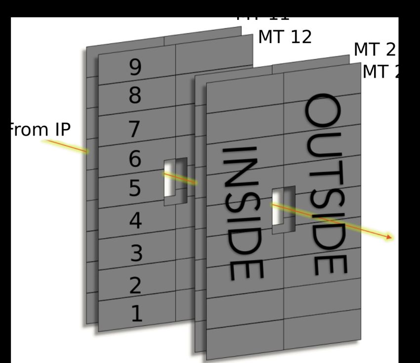
Figure 1. Scheme of the RPCs in the ALICE muon trigger system with the adopted numbering scheme.
Inside and outside refer to detection plane position with respect to the LHC circumference

3 Performance of the ALICE MTR

The ALICE experiment is operating since 2010. The data taking took place in two phases: the RUN
1 (2010-2013) and RUN 2 (2015-2018). During the operations, ALICE has taken data in different
colliding systems: proton-proton (pp), proton-lead (p-Pb), lead-lead (Pb-Pb) and, for a very short
period of time, xenon-xenon (Xe-Xe). The center of mass energies and integrated luminosities
for the RUN 2 data taking period are reported in table 1. The maximum instantaneous luminosity
 √ √
values are about 1031 Hz/cm2 for pp at =5.02 TeV, 5·1030 Hz/cm2 for pp at =13 TeV, 1.5·1029
Hz/cm2 for p-Pb and 1027 Hz/cm2 for Pb-Pb [9].

 Table 1. Running conditions during LHC RUN 2
 √
 System Year(s) ( )
 2015,2017 5.02 ∼ 1.5 −1
 pp
 2015-2018 13 ∼ 36 −1
 p-Pb 2016 5.02, 8.16 ∼3 nb−1 , ∼ 25 nb−1
 Pb-Pb 2015,2018 5.02 ∼800 b−1
 Xe-Xe 2017 5.44 ∼0.3 b−1

 The charge integrated by the RPCs has been monitored since the beginning of operations, using
continuous current measurements after dark current subtraction. The latter is defined as the current
absorbed by the detectors when they are not irradiated (i.e. due to intrinsic noise and cosmic rays)
and is estimated through dedicated cosmic rays runs. The left panel of figure 2 shows the trend of
integrated charge for the MT 22 detection plane (see figure 1) as a function of time. Three curves
are shown: one for the average integrated charge, and two for the RPCs that had accumulated the
highest and the lowest amount of charge by the end of RUN 2. The MT 22 plane was chosen as an
example because it was the one which, on average, accumulated the greatest amount of charge (∼11
mC/cm2 ). Aging tests [5] certified RPC operation with the ALICE gas mixture up to ∼ 50 mC/cm2
of integrated charge.
 The RPC efficiency is constantly monitored, to ensure that the detectors are working as expected
and is an input for efficiency corrections in data analysis. In the right panel of figure 2 the trend
of the average efficiency for the MT 22 detection plane is shown for the whole Run 2. The curve

 –2–
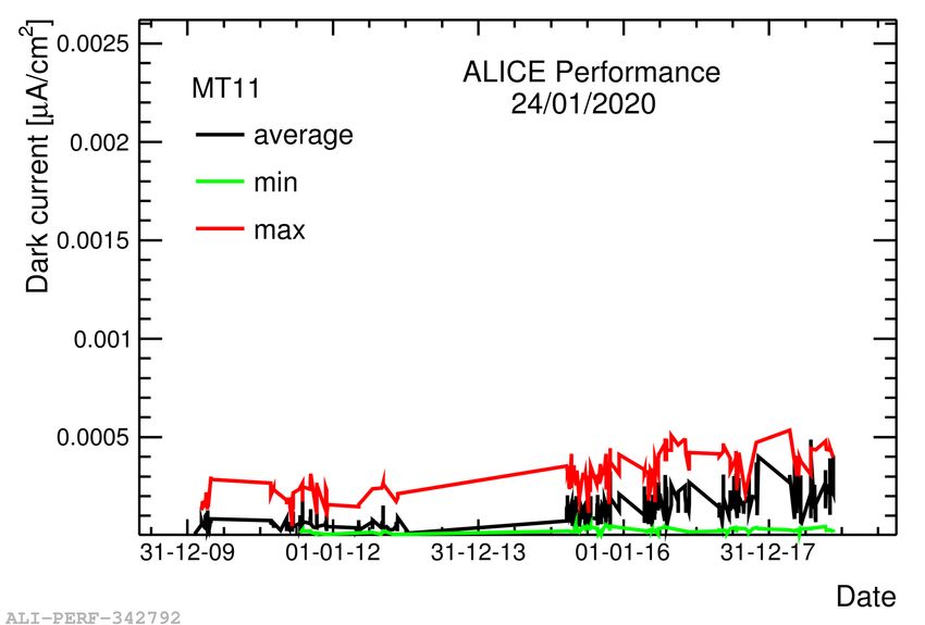
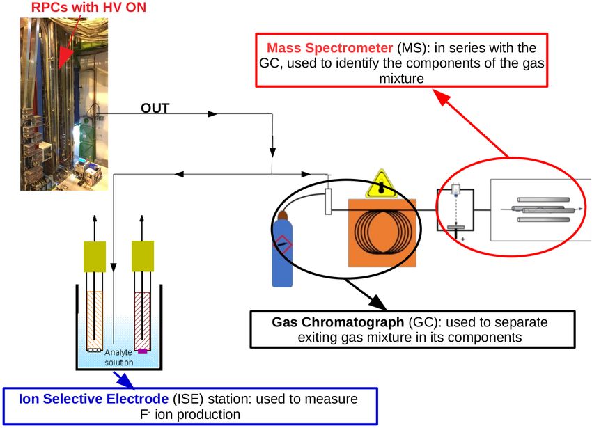
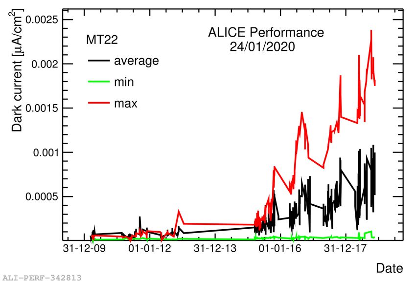
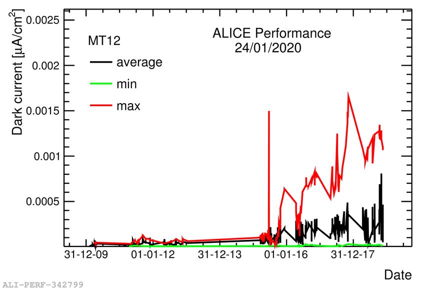
in red refers to the non-bending plane, while the black one to the bending plane. Bending and
non-bending refer to the strip orientation relative to the dipole magnetic field: the strips parallel
(perpendicular) to the magnetic field form the bending (non-bending) plane. The Efficiency showed
satisfactory results for the whole detection system, being typically > 96% and stable over time. The
small fluctuations are mainly due to local issues, such as noise in the front-end electronics. The
MT 22 detection plane was chosen as an example but the behavior of the other planes is similar.
 The detector availability for data taking during RUN 2 was > 95% (the missing 5% also includes
those runs in which the RPCs were kept OFF due to unavailability of other detectors used for muon
physics).

Figure 2. Left panel: integrated charge trend for the MT 22 detection plane, right panel: efficiency trend
for the MT 22 detection plane

 An increase in the average values of dark current can be observed for all four detection planes,
especially during RUN 2, as it can be seen in figure 3. This is the only sign of potential aging
shown by the system since, as stated earlier, the efficiency does not deteriorate over time. The
increase in absorbed dark current was observed on ∼50% of the detectors and the causes are under
investigation.

 Figure 3. Dark current trend for the ALICE muon RPCs.

 –3–
4 Test with Ar plasma

A possible explanation for the observed dark current increase is the deposition of fluorinated
compounds, mainly hydrofluoric acid (HF), on the inner surfaces of the detectors. These compounds
are created by the recombination of F− ions (originated by the breakage of C2 H2 F4 molecules
following their interaction with radiation) with hydrogen, originating mainly from the water vapour
in the mixture. This compound may, at least partially, deposit on the inner surfaces of the detectors,
leading to a degradation of these surfaces and giving rise to the increase in absorbed dark current,
e.g. by chemically attacking the electrodes surface creating local spikes or by forming a thin
conductive layer [10].
 Under this hypothesis, an argon plasma test [11] was executed on two of the MTR RPCs
(active area of 292x77 cm2 each): these detectors were flushed with pure argon and a plasma was
created by ionizing it. A few other detectors (9) were flushed with argon but without ionizing it
and the others were left untouched. The free charges flowing in the plasma, as well as the photons
originating from ion-electron recombinations, may be sufficiently energetic to detach the fluorinated
compounds from the inner surfaces of the detectors and the gas flow would take them out.
 To confirm this assumption, analyses of the exiting gas mixture were performed using a Gas
Chromatograph/Mass Spectrometer (GC/MS) combination, in order to identify the presence of
compounds potentially produced by the interaction of the plasma with the detector, and an Ion
Selective Electrode (ISE) station to identify the presence of F− ions in the exiting gas mixture. The
GC performs the separation of a given gas mixture in its components, thanks to the fact that different
gases are trapped for different times in the GC elements. Each gas exits the GC after a specific time
(retention time) and enters the mass spectrometer (MS) in order to be identified. Each component
of the gas mixture produces a peak in a chromatogram (the result of a GC analysis) and the area
underneath it (measured in V·s) is proportional to the concentration of that particular element.
Figure 4 shows a scheme of the experimental apparatus.

 Figure 4. Scheme of the experimental apparatus for the Ar plasma test.

 A comparison between the dark current absorbed with the standard ALICE gas mixture at the
working point, before and after the Ar plasma test, was also carried out in order to assess whether
this procedure had any effect on it.

 –4–
4.1 F− ions production

The ISE produces a voltage signal proportional to the F− ions concentration which is then converted
into a concentration value (measured in ppm) via a calibration curve. During the Ar plasma test,
integrated measurements were carried out, meaning that the exiting gas was bubbled for a prolonged
period of time (a few hours) in 33 ml of distilled water and a measurement of the F− ions accumulated
in that period of time was done. In figure 5, the cumulative concentration of fluoride ions, gathered
from different measurements, is plotted as a function of the charge integrated during the test.

 Figure 5. Trend of cumulative F− ions concentration as a function of integrated charge.

 The F− concentration was measured before the beginning of the Ar plasma test and found to
be zero, while during the test the concentration was found to increase linearly with the integrated
charge. The most natural explanation is the production of fluorinated compounds, due to the
interaction of the Ar plasma with the inner surfaces of the detectors. The production rate of F−
seems to be constant during the whole test, indicating that the detachment process was still ongoing
after an integrated charge of ∼2.5 mC/cm2 .

4.2 Resistivity studies

When operated with pure Ar, the characteristic current-voltage (I-V) curve for an RPC has the
following features: up to ∼2000 V the Ar is not ionized and no current is circulating in the gas gap.
The gas ionizes rather quickly above 2000 V and, when it reaches full ionization, the I-V curve
follows Ohm’s law. The gas behaves like a short circuit between the two bakelite electrodes, which
can be considered as two resistors in series. From a linear fit to the I-V curve it is possible to extract
the total resistance of the two bakelite electrodes and calculate the mean resistivity of the detector.

 Figure 6. Left: resistivity trend for the two chambers under test

 –5–
In figure 6, the resistivity of the two detectors under test is shown as a function of the charge
accumulated during the Ar plasma test. The resistivity, for both chambers, shows hints of an
increasing trend with the integrated charge. This might be related to a drying effect that the plasma
is having either on the bakelite or on the linseed oil coating, as it is suggested in [12].

4.3 CO2 production
Besides Ar and water, already present at the input of the detectors, another compound was identified
by the GC/MS analyses, when the detectors were switched on and the plasma was created. This
was identified as CO2 .
 The CO2 concentration was correlated with the circulating current, as shown in figure 7: mea-
surements have been taken at different values of current and the CO2 concentration was calculated
for each analysis. In the left portion of figure 7 all the results are shown, while in the right portion
the average values of concentration are plotted as a function of the average values of applied current.
The linear fit clearly shows a correlation between the two quantities.

Figure 7. Correlation between CO2 concentration and circulating current. The values in ppm for the CO2
concentration have been obtained by means of a calibration curve.

4.4 Dark current comparison
The dark current with the standard gas mixture at the working point was measured before and after
the tests. The observed small variations are compatible with those observed for the RPCs which
were not treated.

5 Conclusions

The RPCs of the ALICE muon trigger system have shown satisfactory results during the LHC RUN
2: efficiency was > 96% and stable over time, detector availability was over 95%; some of the
detectors have accumulated an amount of charge close to their certified lifetime and may have to be
replaced before LHC RUN 3 [1].
 An increase in the absorbed dark current was observed. In order to gain further insights on
such an increase, an argon plasma test was carried out and the following observations have been
made: (i) F− ions were present in the exiting gas mixture and their concentration was correlated
with the charge accumulated in the test, (ii) hints of an increasing trend of the RPCs resistivity, (iii)
the production of CO2 and its correlation with the circulating current, (iv) a comparison between
the dark current before and after the test showed no significant difference.

 –6–
References

 [1] L. Terlizzi, The ALICE Muon IDentifier (MID), in these proceedings.
 [2] ALICE Collaboration, The ALICE experiment at the CERN LHC, Journal of Instrumentation, 2008,
 3.08: S08002.
 √
 [3] ALICE Collaboration, Υ suppression at forward rapidity in Pb-Pb collisions at = 5.02 TeV,
 Physics Letters B, vol. 709, pp 89–101, 2019
 [4] ALICE collaboration, ALICE Technical Design Report of the Dimuon Forward Spectrometer,
 CERN-LHCC-99-022
 [5] R. Arnaldi et al, Beam and ageing tests with a highly-saturated avalanche gas mixture for the ALICE
 p-p data taking, Nuclear Physics B - Proceedings Supplements, vol. 158, pp 149–153, 2006.
 [6] F. Bossú et al., Performance of the RPC-based ALICE muon trigger system at the LHC, Journal of
 Instrumentation, vol. 7, pp T12002–T12002, 2012.
 [7] R. Arnaldi et al., R&D on RPC for the muon trigger system for the ALICE experiment in view of p-p
 data taking, IEEE Symposium Conference Record Nuclear Science 2004, vol. 2, pp 1265–1269, 2004.
 [8] R. Arnaldi et al., Front-end electronics for the RPCs of the ALICE dimuon trigger, IEEE Transactions
 on Nuclear Science, vol. 52, pp 1176–1181, 2005.
 [9] M. Gagliardi, Detector and trigger performance in ALICE during the LHC Run 2, presented to the
 International Conference on New Frontiers in Physics, Athens, 21–29 August 2019
 https://indico.cern.ch/event/754973/contributions/3535438/.
[10] M. Abbrescia, V. Peskov, P. Fonte, Resistive Gaseous Detectors: Designs, Performance, and
 Perspectives, Wiley-VCH 2018.
[11] G. Aielli et al., Fluoride production in RPCs operated with F-compound gases, Nuclear Physics B
 (Proc. Suppl.), vol. 158, pp 143–148, 2006.
[12] J. Va’vra, Physics and chemistry of aging - early developments, Nuclear Instruments and Methods in
 Physics Research A, vol. 515, pp 1–14, 2003.

 –7–
You can also read