Preparation of Porous Carbon Nanofibers with Tailored Porosity for Electrochemical Capacitor Electrodes - MDPI
←
→
Page content transcription
If your browser does not render page correctly, please read the page content below
materials
Article
Preparation of Porous Carbon Nanofibers with
Tailored Porosity for Electrochemical
Capacitor Electrodes
Jisu Kim 1 , Youn-Ji Heo 2 , Jin-Yong Hong 2, * and Sung-Kon Kim 1,3, *
 1   School of Semiconductor and Chemical Engineering, Jeonbuk National University, 567 Baekje-daero,
     Deokjin-gu, Jeonju-si, Jeollabuk-do 54896, Korea; okjisu@naver.com
 2   Carbon Industry Frontier Research Center, Korea Research Institute of Chemical Technology (KRICT),
     Daejeon 34114, Korea; yjheo@krict.re.kr
 3   School of Chemical Engineering, Jeonbuk National University, 567 Baekje-daero, Deokjin-gu, Jeonju-si,
     Jeollabuk-do 54896, Korea
 *   Correspondence: jyhong@krict.re.kr (J.-Y.H.); skkim@jbnu.ac.kr (S.-K.K.)

 Received: 2 January 2020; Accepted: 2 February 2020; Published: 5 February 2020

 Abstract: Porous carbon electrodes that accumulate charges at the electrode/electrolyte interface
 have been extensively investigated for use as electrochemical capacitor (EC) electrodes because of
 their great attributes for driving high-performance energy storage. Here, we report porous carbon
 nanofibers (p-CNFs) for EC electrodes made by the formation of a composite of monodisperse silica
 nanoparticles and polyacrylonitrile (PAN), oxidation/carbonization of the composite, and then silica
 etching. The pore features are controlled by changing the weight ratio of PAN to silica nanoparticles.
 The electrochemical performances of p-CNF as an electrode are estimated by measuring cyclic
 voltammetry and galvanostatic charge/discharge. Particularly, the p-CNF electrode shows exceptional
 areal capacitance (13 mF cm−2 at a current of 0.5 mA cm−2 ), good rate-retention capability (~98%
 retention of low-current capacitance), and long-term cycle stability for at least 5000 charge/discharge
 cycles. Based on the results, we believe that this electrode has potential for use as high-performance
 EC electrodes.

 Keywords: electrochemical capacitor; energy storage; carbon nanofiber; porosity; polyacrylonitrile

1. Introduction
     Among the different kinds of energy storage devices, electrochemical capacitors (ECs), also
termed supercapacitors, are creating new opportunities in applications in which high power, fast
charge/discharge, and long-lasting operation are needed [1–5], because energy for ECs can be stored
as the charge accumulates on the electrode surface. For high energy and power, a significant
electrical conductivity and high surface area are required for electrode materials. In spite of these
advantages, the relatively small energy density of ECs over those of conventional rechargeable
batteries limits their commercial utilization [6–10]. In this regard, advances in high-energy ECs
have been devoted toward the preparation of highly efficient electrodes that are a determinant of
electrochemical performances [11,12]. A number of notable examples in electrode materials have been
created using porous carbon nanomaterials, while maintaining their intrinsic attributes. Particularly,
nanostructuring of the pores of carbon nanomaterials is significant for fast mass transports, and ion
diffusion through the pores can greatly improve electrochemical reactions at the electrode/electrolyte
interface [13–16]. Three-dimensional (3D) porous nanoarchitecture have been created, in which pores
and active materials are interconnected, leading to fast movements for both ions and electrons [17–20].
Porous nanostructures have been commonly created through self-assembly or template-assisted

Materials 2020, 13, 729; doi:10.3390/ma13030729                                 www.mdpi.com/journal/materials
Materials 2020, 13, 729                                                                              2 of 9

strategies [21–23]. For self-assembly, difficulties have been encountered in forming a well-organized
pore network in electrodes [24,25]. Pores are randomly distributed, sometimes not well-interconnected,
and vary in size, and self-assembly is induced by randomly aggregating carbon nanomaterials [26–29].
This structure could possibly induce large ohmic resistance and incomplete wetting of electrodes
by electrolytes, leading to a large voltage drop at high currents [30–32]. In one successful example
of template-assisted methods, Choi et al. prepared 3D microporous, chemically modified graphene
starting with polystyrene colloids as a sacrificial template [19]. When graphene was initially used as
the electrode materials for a supercapacitor in the form of packed (or dense) film, the electrochemical
performance was not significant because the electrical double layer (EDL) between the electrode and
electrolyte was not well made. However, as graphene was made in a 3D structure, the pores were
notably formed. This affects the diffusional (or mass transport) behavior of electrochemical systems
and provides significant EDLs, which are important for capacitance, rate-dependent capability, and
energy and power densities. As such, the development of a well-organized porous structure is highly
desirable, yet very challenging.
      One-dimensional (1D) structured carbon materials are advantageous to charge carrier mobility
along the axial direction, offering the potential of being used in energy storage [33]. However, low the
capacitance and energy density of 1D carbon electrodes, due to the difficulties of their pore size/size
distribution controls, should be improved for practical applications [34–38]. Recently, studies on 1D
carbon materials have been particularly driven toward the fabrication of highly porous structures with
controlled pore size distributions.
      Here we report nanoporous carbon nanofibers prepared by the carbonization of electrospun
polyacrylonitrile (PAN), embedding monodisperse silica nanoparticles as a sacrificial template [39,40].
The chemical etching of the silica enables a nanoporous structure to form without affecting the electronic
properties of PAN-based carbon nanofibers. Such a 3D porous network structure provides a facilitated
transport path for electrolyte ions and electrons [41].

2. Materials and Methods

2.1. Materials
     Polyacrylonitile (PAN, Mw = 150,000 g mol−1 ), N,N-Dimethylformamide (DMF, ≥ 99.8%,
Mw = 73.09 g mol−1 ) and tetraethyl orthosilicate (TEOS, 98%, Mw = 208.33 g mol−1 ) were supplied
by Sigma-Aldrich (Korea). Hydrofluoric acid (HF, Mw = 20.01 g mol−1 ) was supplied by J.T. Baker.
Ammonium hydroxide solution (NH4 OH, 28.0–30.0%, Mw = 35.05 g mol−1 ) was supplied by SAMCHUN
(Korea).

2.2. Preparation of Porous Carbon Nanofibers
      Silica nanoparticles were synthesized using the Stöber method [42]. Silica nanoparticles (500 wt%
relative to polyacrylonitrile (PAN)) were mixed with 8 wt% PAN in DMF. The solution was stirred for
24 h at 50 ◦ C and then ultrasonicated for 6 h at 50 ◦ C to obtain a homogeneous solution. Composite
nanofibers were produced via electrospinning. A 12-mL syringe with a 23-gauge metal nozzle was
used for electrospinning. A high voltage supplier was used to provide a varying voltage, of 11.0, 13.0,
and 14.0 kV, to the syringe needle tip and a metal drum collector (NanoNC, Korea). The electrospun
composite nanofibers were collected on a metal drum collector that was covered with aluminum
foil at the feed rate at 10 µL/min. The distance between the tip of the needle and the collector was
15 cm. The resulting composite nanofibers were dried in a vacuum oven for 12 h at 70 ◦ C. Porous
carbon nanofibers were formed by oxidation and subsequent carbonization of PAN/silica composite
nanofibers. PAN/silica composite nanofibers were heated to 260 ◦ C at a rate of 1 ◦ C min−1 and held at
that temperature for 3 h in an air atmosphere. Carbonization was performed by heating to 900 ◦ C at a
rate 2 ◦ C min−1 in a N2 atmosphere and then the temperature was maintained for 3 h. The carbonized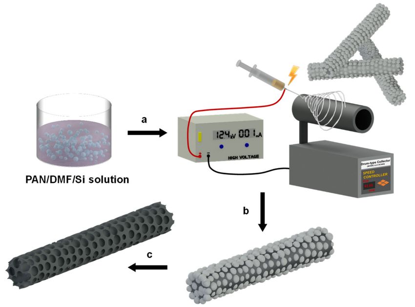
Materials 2020, 13, 729                                                                                         3 of 9

composite nanofibers were soaked in HF for 6 h at 25 ◦ C to remove silica nanoparticles. The resulting
porous carbon nanofibers were dried at room temperature.

2.3. Characterization
     N2 adsorption/desorption isotherms were determined at 77.3 K using a surface area analyzer
(ASAP 2420 V2.09K, Micromeritics, USA). Prior to measurements, the samples were preheated at
450 ◦ C for 3 h under vacuum to remove any moisture or dust from within the pores of the samples.
The Brunauer–Emmett–Teller (BET) model was used to calculate the specific surface area of the
samples from the N2 adsorption isotherms in a relative pressure (P/P0 ) range of 0.02 to 0.06. Surface
and cross-section images of porous carbon nanofibers were acquired by field emission scanning
electron microscopy (FE-SEM, Philips XL30S FEG, Netherlands) at magnifications of ×100 to ×150 k,
and at an accelerating voltage of 10 to 20 kV. Before observation, the samples were coated with
a thin layer by spraying platinum (Pt) for 120 s using a Quorum Q 150T ES. Cyclic voltammetry
(CV), galvanostatic charge/discharge (GCD), and electrochemical impedance spectroscopy (EIS) were
performed using an SP-200 potentiostat (Bio-Logic, Knoxville, TN, USA) in 1.0 M H2 SO4 aqueous
electrolyte in two-electrode mode at room temperature. The EIS test was conducted over the frequency
range of 106 to 10−2 Hz at the amplitude of the sinusoidal voltage by applying a 5-mV signal. In the
GCD profiles, the specific capacitance could be estimated using the following equation:

                                               C = 4I/[(∆V/∆t)A]                                                  (1)

where I is the current applied, ∆V/∆t is the slope of the discharge curve after the IR drop at the
beginning of the discharge curve, and A is the total area of two electrodes.

3. Results and Discussion
      Porous carbon nanofibers (termed p-CNFs) were fabricated in four major steps: (1) electrospinning
of polyacrylonitrile (PAN)/silica composite nanofibers; (2) oxidative stabilization at 260 ◦ C in air;
(3) carbonization at 900 ◦ C under a nitrogen atmosphere; and (4) the removal of silica in a hydrogen
fluoride aqueous solution for 6 h at room temperature (Figure 1).

      Figure 1. Schematic illustration of the fabrication process for porous carbon nanofibers (p-CNFs).
      The major steps of the fabrication process were: (a) Electrospinning the polyacrylonitrile (PAN)/silica
      solution using a metal drum collector. (b) Oxidation of the PAN/silica nanofibers in air at 260 ◦ C,
      then carbonization at 900 ◦ C under a slow stream of nitrogen. (c) Removal of silica nanoparticles by
      immersing in hydrofluoric acid (HF) solution for 6 h.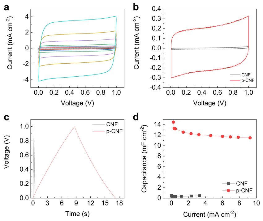
Materials 2020, 13, 729                                                                                     4 of 9

      Monodisperse silica nanoparticles were formed using the Stöber method [42]. The mean particle
size of the silica was about 50 nm, which was determined by SEM. Neat PAN-based CNFs were also
prepared using the same protocol, except for the use of silica nanoparticles. Figure 2 shows the FE-SEM
images of neat PAN-based CNF, electrospun PAN/silica-basis composite carbon nanofibers, and p-CNF.
Well-distributed silica nanoparticles, which were fugitive, in PAN/silica composite carbon nanofibers
left pores in p-CNF after the silica etching process. As such, the p-CNF had pores evenly distributed in
the fibers. This was due to the good dispersion of the silica nanoparticles in the PAN solution. Fiber
diameters ranging from 250 to 300 nm were preserved after the carbonization and etching processes.

      Figure 2. FE-SEM images of (a) neat CNF, (b) PAN/silica composite carbon nanofiber, and (c) p-CNF
      (insets: cross-sectional SEM images, scale bars = 200 nm).

    Porosity of the p-CNF was adjusted by changing the wt% of silica nanoparticles to PAN ranging
from 350 to 700 wt% because it depended on the amounts of silica nanoparticles that adhered to the
CNF surface. Figure 3 shows FE-SEM images of p-CNFs prepared using different silica nanoparticles
contents. Not surprisingly, the porosity of the p-CNFs increased by increasing the content of silica
nanoparticles from 350 to 500 wt%. No significant change in porosity of p-CNF was observed when
750 wt% of silica nanoparticles were added to the PAN solution when compared to 500 wt% silica
content. Accordingly, we limited the discussion here to p-CNF prepared by using PAN solution with
500 wt% silica nanoparticles.

      Figure 3. FE-SEM images of p-CNFs prepared by 8 wt% PAN dissolved in DMF solution with (a) 350
      wt%, (b) 500 wt%, and (c) 700 wt% silica nanoparticle contents (insets: cross-sectional SEM images,
      scale bars = 200 nm).

      Pore characteristics of CNF and p-CNF were investigated using N2 sorption measurements. The
specific surface area, micropore area, pore volume and pore size are summarized in Table 1. The
uniformly dispersed silica nanoparticles in the CNF offered numerous channels to interconnect with
the micropores, leading to an increase in the surface area. As a result, the p-CNF had a specific surface
area of 391 m2 g−1 , which isapproximately 1.8 times higher than that of CNF (214 m2 g−1 ). The pore
volume of p-CNF determined by Barrett–Joyner–Halenda (BJH) pore size distribution was also larger
than CNF. These observations are presumably due to pores that were formed after removal of the
silica nanoparticles.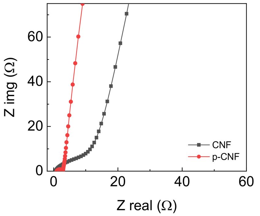
Materials 2020, 13, 729                                                                                                    5 of 9

                                  Table 1. Pore characteristics of CNF and p-CNF.

                          Specific Surface     Micropore Area 2         Pore Volume 3
          Samples                                                                                   Pore Size 1 (nm)
                           Area 1 (m2 /g)           (m2 /g)                (cm2 /g)
           CNF                214.19                 198.74                  0.118                       2.218
          p-CNF               391.43                 260.22                  0.987                       10.088
      1These values are estimated by using the Brunauer–Emmett–Teller (BET) model.   2   Estimated by t-plot method.   3

      These values are estimated by using the Barrett–Joyner–Halenda (BJH) model.

     Judging from these data, it can be concluded that the silica nanoparticles were successfully
introduced into the CNF without any structural collapse. Furthermore, the interconnected pore
structure of p-CNF with a high surface area was expected to increase wettability of electrolyte, and
thus enable them to be used as highly efficient electrode for ECs.
     The electrochemical characterizations of p-CNF and CNF electrodes were carried out by
two-electrode cyclic voltammetry (CV) and galvanostatic charge/discharge (GCD) tests over the
voltage window of 1 V in 1.0 M H2 SO4 aqueous electrolyte at room temperature. Figure 4a shows
the CV curves of p-CNF and CNF electrodes, both of which retain nearly box-like curves even up to
a high scan rate of 1000 mV s−1 . This is indicative of excellent charge propagation across electrodes.
Additionally, the current induced by charge accumulation for p-CNF is significantly larger than that of
CNF at a constant scan rate of 50 mV s−1 (Figure 4b). The corresponding areal capacitance is 38 mF
cm−2 , 37-fold greater than 1.0 mF cm−2 of CNF. This observation was supported by performing GCD
measurements over the currents of 0.04 to 9.3 mA cm−2 . A longer triangular GCD profile of p-CNT
electrode than that of a CNF electrode demonstrated that the former electrodes accumulated the larger
amount of EDLs on the surface (Figure 4c). The areal capacitance of p-CNF is 13 mF cm−2 , 38-times
larger than 0.34 mF cm−2 of CNF, which was comparable to values of other state-of-the-art electrical
double layer capacitor (EDLC) type electrodes reported [43–45]. Fast charge–discharge behavior within
seconds was also observed, leading to high power capability. Rate-retention performance was obtained
by calculating the discharge curve of the GCD (Figure 4d). The areal capacitance of 14 mF cm−2 for
p-CNF at low current of 0.23 mA cm−2 was retained by 79% even at a large areal-based current of 9.3
mA cm−2 , proving exceptional rate-retention capability.

      Figure 4. (a) Cyclic voltammetry (CV) curves of p-CNF electrode at scan rates of 10 to 1000 mV s−1 .
      (b) CV curves (at a constant scan rate of 50 mV s−1 ), (c) galvanostatic charge/discharge (GCD) profiles
      (at a constant current of 0.5 mA cm−2 ), and (d) rate-retention capability of CNF and p-CNF electrodes.
Materials 2020, 13, 729 6 of 9
The additional details of why p-CNF exhibited better performance than CNF were identified
through electrochemical impedance spectroscopy measurements over a frequency range of 106 to
10−2 Hz (Figure 5). The intercept of the real part of the Nyquist plot was related to the equivalence
series resistance (ESR) that was attributed to the combination of electrode and electrolyte resistances
and contact resistance between the current collector and electrode. The ESR for p-CNF was quite
small, 3.0 Ω, close to 1.1 Ω of CNF, which indicated that pore formation via a silica template did not
aggravate the electrical property of p-CNF. The intermediate frequency region of the Nyquist plots,
i.e., 45◦ Warburg region, exhibited the slope deviated from the vertical line of ideal resistor-capacitor
(RC) circuit, attributed to the limited ion diffusion of the electrolyte [46]. The p-CNF electrodes
displayed much shorter Warburg length than CNF electrodes, and demonstrated faster ion diffusion
across electrode/electrolyte interface due to the porous pores in p-CNF [47,48]. The nonporous CNF
electrode resulted in relatively longer Warburg length, reflecting slow ion kinetics. The more vertical
slope of the p-CNF electrode than that of the CNF electrode in the low-frequency region indicated a
purely capacitive behavior. With the results we observed, we can conclude that better electrochemical
performances of the p-CNF electrode than the neat CNF electrode were due to the electrode/electrolyte
interface largely formed throughout the porous nanofiber electrodes.
Figure 5. Nyquist plots of CNF and p-CNF electrodes.
Long-term cycle stability of the p-CNF electrode was confirmed over repeated 5000 GCD cycles at
a constant current of 0.19 mA cm−2 (Figure 6). The electrode retained ~98% of initial areal capacitance
and nearly 100% of coulombic efficiency for at least 5000 GCD cycles, demonstrating good cycle stability.
Figure 6. Long-term cycle stability and coulombic efficiency of p-CNF over 5000 GCD cycles at 0.19
mA cm−2 . C0 is the initial capacitance and C is the capacitance at the indicated number of cycles.
4. Conclusions
In conclusion, the present work demonstrated that the concept of porous carbon design holds
great potential as an electrochemical energy storage. Starting from electrospun PAN/silica composites,
p-CNFs were formed via oxidation/carbonization and subsequent silica etching. The porosity of p-CNFs
was modulated by a simple change of wt% of PAN to silica nanoparticles. The optimum weight% wasMaterials 2020, 13, 729 7 of 9
found to be 500 wt%. Cyclic voltammetry and galvanostatic charge/discharge results demonstrated
that p-CNF electrodes revealed better electrochemical performances with respect to areal capacitance
and rate performance than neat CNF electrodes. This relatively high-performance of p-CNF was
due to enhanced wettability of electrode by electrolyte through well-connected pores, synergistically
improving the effective surface area of the electrode/electrolyte interface. Additionally, they exhibited
exceptional long cycle lives and coulombic efficiency for at least 5000 charge/discharge cycles.
Author Contributions: Conceptualization and methodology, J.-Y.H. and S.-K.K.; investigation and data curation,
J.K., Y.-J.H., J.-Y.H. and S.-K.K.; writing—original draft preparation, J.K., Y.-J.H., J.-Y.H. and S.-K.K.; writing—review
and editing, J.-Y.H. and S.-K.K.; visualization, J.K., Y.-J.H.; supervision, J.-Y.H. and S.-K.K.; project administration,
J.-Y.H. and S.-K.K., J.K. and Y.-J.H. contributed equally to this work. All authors have read and agreed to the
published version of the manuscript.
Funding: This research received no external funding.
Acknowledgments: J.-Y.H. acknowledges the support from the Basic Science Research Program through the
National Research Foundation of Korea (NRF) funded by the Ministry of Education (NRF-2017R1C1B2007153).
This work was also supported by Basic Science Research Program through the National Research Foundation of
Korea (NRF) funded by the Ministry of Education (NRF-2018R1D1A3B07048748).
Conflicts of Interest: The authors declare no conflict of interest.
References
1. Zhao, M.-Q.; Zhang, Q.; Huang, J.-Q.; Tian, G.-L.; Chen, T.-C.; Qian, W.-Z.; Wei, F. Towards high purity
graphene/single-walled carbon nanotube hybrids with improved electrochemical capacitive performance.
Carbon 2013, 54, 403–411. [CrossRef]
2. Vangari, M.; Pryor, T.; Jiang, L. Supercapacitors: Review of materials and fabrication methods. J. Energy Eng.
2013, 139, 72–79. [CrossRef]
3. Guo, Q.; Zhou, X.; Li, X.; Chen, S.; Seema, A.; Greiner, A.; Hou, H. Supercapacitors based on hybrid carbon
nanofibers containing multiwalled carbon nanotubes. J. Mater. Chem. 2009, 19, 2810–2816. [CrossRef]
4. Wang, K.; Wang, Y.; Wang, Y.; Hosono, E.; Zhou, H. Mesoporous carbon nanofibers for supercapacitor
application. J. Phys. Chem. C 2009, 113, 1093–1097. [CrossRef]
5. Yu, D.; Zhai, S.; Jiang, W.; Goh, K.; Wei, L.; Chen, X.; Jiang, R.; Chen, Y. Transforming pristine carbon fiber
tows into high performance solid-state fiber supercapacitors. Adv. Mater. 2015, 27, 4895–4901. [CrossRef]
[PubMed]
6. Simon, P.; Gogotsi, Y. Materials for electrochemical capacitors. Nat. Mater. 2008, 7, 845–854. [CrossRef]
[PubMed]
7. Qu, G.; Cheng, J.; Li, X.; Yuan, D.; Chen, P.; Chen, X.; Wang, B.; Peng, H. A fiber supercapacitor with
high energy density based on hollow graphene/conducting polymer fiber electrode. Adv. Mater. 2016, 28,
3646–3652. [CrossRef]
8. Liu, C.; Yu, Z.; Neff, D.; Zhamu, A.; Jang, B.Z. Graphene-based supercapacitor with an ultrahigh energy
density. Nano Lett. 2010, 10, 4863–4868. [CrossRef]
9. El-Kady, M.F.; Ihns, M.; Li, M.; Hwang, J.Y.; Mousavi, M.F.; Chaney, L.; Lech, A.T.; Kaner, R.B. Engineering
three-dimensional hybrid supercapacitors and microsupercapacitors for high-performance integrated energy
storage. Proc. Natl. Acad. Sci. USA 2015, 112, 4233. [CrossRef]
10. Chen, T.; Dai, L. Flexible supercapacitors based on carbon nanomaterials. J. Mater. Chem. A 2014, 2,
10756–10775. [CrossRef]
11. Shi, Z.; Chu, W.; Hou, Y.; Gao, Y.; Yang, N. Asymmetric supercapacitors with high energy densities. Nanoscale
2019, 11, 11946–11955. [CrossRef] [PubMed]
12. Tahir, M.; He, L.; Haider, W.A.; Yang, W.; Hong, X.; Guo, Y.; Pan, X.; Tang, H.; Li, Y.; Mai, L. Co-electrodeposited
porous PEDOT–CNT microelectrodes for integrated micro-supercapacitors with high energy density, high
rate capability, and long cycling life. Nanoscale 2019, 11, 7761–7770. [CrossRef] [PubMed]
13. Chen, L.-F.; Zhang, X.-D.; Liang, H.-W.; Kong, M.; Guan, Q.-F.; Chen, P.; Wu, Z.-Y.; Yu, S.-H. Synthesis of
nitrogen-doped porous carbon nanofibers as an efficient electrode material for supercapacitors. ACS Nano
2012, 6, 7092–7102. [CrossRef]Materials 2020, 13, 729 8 of 9
14. Qin, K.; Kang, J.; Li, J.; Shi, C.; Li, Y.; Qiao, Z.; Zhao, N. Free-standing porous carbon nanofiber/ultrathin
graphite hybrid for flexible solid-state supercapacitors. ACS Nano 2015, 9, 481–487. [CrossRef]
15. Zhang, X.; Shi, W.; Zhu, J.; Zhao, W.; Ma, J.; Mhaisalkar, S.; Maria, T.L.; Yang, Y.; Zhang, H.; Hng, H.H.; et al.
Synthesis of porous NiO nanocrystals with controllable surface area and their application as supercapacitor
electrodes. Nano Res. 2010, 3, 643–652. [CrossRef]
16. He, X.; Zhao, N.; Qiu, J.; Xiao, N.; Yu, M.; Yu, C.; Zhang, X.; Zheng, M. Synthesis of hierarchical porous
carbons for supercapacitors from coal tar pitch with nano-Fe2 O3 as template and activation agent coupled
with KOH activation. J. Mater. Chem. A 2013, 1, 9440–9448. [CrossRef]
17. Qie, L.; Chen, W.; Xu, H.; Xiong, X.; Jiang, Y.; Zou, F.; Hu, X.; Xin, Y.; Zhang, Z.; Huang, Y. Synthesis of
functionalized 3D hierarchical porous carbon for high-performance supercapacitors. Energy Environ. Sci.
2013, 6, 2497–2504. [CrossRef]
18. Shi, Y.; Pan, L.; Liu, B.; Wang, Y.; Cui, Y.; Bao, Z.; Yu, G. Nanostructured conductive polypyrrole hydrogels as
high-performance, flexible supercapacitor electrodes. J. Mater. Chem. A 2014, 2, 6086–6091. [CrossRef]
19. Choi, B.G.; Yang, M.; Hong, W.H.; Choi, J.W.; Huh, Y.S. 3D Macroporous graphene frameworks for
supercapacitors with high energy and power densities. ACS Nano 2012, 6, 4020–4028. [CrossRef]
20. Song, S.; Ma, F.; Wu, G.; Ma, D.; Geng, W.; Wan, J. Facile self-templating large scale preparation of
biomass-derived 3D hierarchical porous carbon for advanced supercapacitors. J. Mater. Chem. A 2015, 3,
18154–18162. [CrossRef]
21. Yu, B.; Kuang, D.; Liu, S.; Liu, C.; Zhang, T. Template-assisted self-assembly method to prepare
three-dimensional reduced graphene oxide for dopamine sensing. Sens. Actuator B-Chem. 2014, 205,
120–126. [CrossRef]
22. Xing, Z.; Geng, B.; Li, X.; Jiang, H.; Feng, C.; Ge, T. Self-assembly fabrication of 3D porous quasi-flower-like
ZnO nanostrip clusters for photodegradation of an organic dye with high performance. CrystEngComm 2011,
13, 2137–2142. [CrossRef]
23. Jeon, Y.S.; Kim, S.H.; Park, B.C.; Nam, D.Y.; Kim, Y.K. Synthesis of Co nanotubes by nanoporous
template-assisted electrodeposition via the incorporation of vanadyl ions. ChemComm 2017, 53, 1825–1828.
[CrossRef] [PubMed]
24. Dubal, D.P.; Holze, R.; Kulal, P.M. Enhanced supercapacitive performances of hierarchical porous
nanostructure assembled from ultrathin MnO2 nanoflakes. J. Mater. Sci. 2013, 48, 714–719. [CrossRef]
25. Luo, Y.; Jiang, J.; Zhou, W.; Yang, H.; Luo, J.; Qi, X.; Zhang, H.; Yu, D.Y.W.; Li, C.M.; Yu, T. Self-assembly of
well-ordered whisker-like manganese oxide arrays on carbon fiber paper and its application as electrode
material for supercapacitors. J. Mater. Chem. 2012, 22, 8634–8640. [CrossRef]
26. Ma, G.; Yan, X.; Li, Y.; Xiao, L.; Huang, Z.; Lu, Y.; Fan, J. Ordered nanoporous silica with periodic 30−60 nm
pores as an effective support for gold nanoparticle catalysts with enhanced lifetime. J. Am. Chem. Soc. 2010,
132, 9596–9597. [CrossRef]
27. Yin, Y.; Liu, C.; Fan, S. Well-constructed CNT mesh/PANI nanoporous electrode and its thickness effect on
the supercapacitor properties. J. Phys. Chem. C 2012, 116, 26185–26189. [CrossRef]
28. Fan, W.; Miao, Y.-E.; Huang, Y.; Tjiu, W.W.; Liu, T. Flexible free-standing 3D porous N-doped graphene–carbon
nanotube hybrid paper for high-performance supercapacitors. RSC Adv. 2015, 5, 9228–9236. [CrossRef]
29. Wang, Q.; Yan, J.; Wang, Y.; Wei, T.; Zhang, M.; Jing, X.; Fan, Z. Three-dimensional flower-like and hierarchical
porous carbon materials as high-rate performance electrodes for supercapacitors. Carbon 2014, 67, 119–127.
[CrossRef]
30. Wang, D.-W.; Li, F.; Fang, H.-T.; Liu, M.; Lu, G.-Q.; Cheng, H.-M. Effect of pore packing defects in 2-D ordered
mesoporous carbons on ionic transport. J. Phys. Chem. B 2006, 110, 8570–8575. [CrossRef]
31. Wang, D.-W.; Li, F.; Liu, M.; Lu, G.Q.; Cheng, H.-M. 3D aperiodic hierarchical porous graphitic carbon
material for high-rate electrochemical capacitive energy storage. Angew. Chem. Int. Ed. 2008, 47, 373–376.
[CrossRef] [PubMed]
32. Yoon, S.; Lee, J.; Hyeon, T.; Oh, S.M. Electric double-layer capacitor performance of a new mesoporous
carbon. J. Electrochem. Soc. 2000, 147, 2507–2512. [CrossRef]
33. Na, W.; Jun, J.; Park, J.W.; Lee, G.; Jang, J. Highly porous carbon nanofibers co-doped with fluorine and
nitrogen for outstanding supercapacitor performance. J. Mater. Chem. A 2017, 5, 17379–17387. [CrossRef]Materials 2020, 13, 729 9 of 9
34. Ling, Z.; Wang, Z.; Zhang, M.; Yu, C.; Wang, G.; Dong, Y.; Liu, S.; Wang, Y.; Qiu, J. Sustainable
synthesis and assembly of biomass-derived B/N co-doped carbon nanosheets with ultrahigh aspect ratio for
high-performance supercapacitors. Adv. Funct. Mater. 2016, 26, 111–119. [CrossRef]
35. Zhang, G.; Song, Y.; Zhang, H.; Xu, J.; Duan, H.; Liu, J. Radially aligned porous carbon nanotube arrays on
carbon fibers: A hierarchical 3D carbon nanostructure for high-performance capacitive energy storage. Adv.
Funct. Mater. 2016, 26, 3012–3020. [CrossRef]
36. Yanilmaz, M.; Dirican, M.; Asiri, A.M.; Zhang, X. Flexible polyaniline-carbon nanofiber supercapacitor
electrodes. J. Energy Storage 2019, 24, 100766. [CrossRef]
37. Ambade, R.B.; Ambade, S.B.; Shrestha, N.K.; Salunkhe, R.R.; Lee, W.; Bagde, S.S.; Kim, J.H.; Stadler, F.J.;
Yamauchi, Y.; Lee, S.-H. Controlled growth of polythiophene nanofibers in TiO2 nanotube arrays for
supercapacitor applications. J. Mater. Chem. A 2017, 5, 172–180. [CrossRef]
38. Duy, L.X.; Peng, Z.; Li, Y.; Zhang, J.; Ji, Y.; Tour, J.M. Laser-induced graphene fibers. Carbon 2018, 126, 472–479.
[CrossRef]
39. Almuhamed, S.; Khenoussi, N.; Bonne, M.; Schacher, L.; Lebeau, B.; Adolphe, D.; Brendlé, J. Electrospinning
of PAN nanofibers incorporating SBA-15-type ordered mesoporous silica particles. Eur. Polym. J. 2014, 54,
71–78. [CrossRef]
40. Wu, Q.-Y.; Liang, H.-Q.; Li, M.; Liu, B.-T.; Xu, Z.-K. Hierarchically porous carbon membranes derived from
PAN and their selective adsorption of organic dyes. Chin. J. Polym. Sci. 2016, 34, 23–33. [CrossRef]
41. Jiang, H.; Lee, P.S.; Li, C. 3D carbon based nanostructures for advanced supercapacitors. Energy Environ. Sci.
2013, 6, 41–53. [CrossRef]
42. Stöber, W.; Fink, A.; Bohn, E. Controlled growth of monodisperse silica spheres in the micron size range. J.
Colloid Interface Sci. 1968, 26, 62–69. [CrossRef]
43. Lekakou, C.; Moudam, O.; Markoulidis, F.; Andrews, T.; Watts, J.F.; Reed, G.T. Carbon-based fibrous EDLC
capacitors and supercapacitors. J. Nanotechnol. 2011, 2011, 409382. [CrossRef]
44. Huang, P.; Heon, M.; Pech, D.; Brunet, M.; Taberna, P.-L.; Gogotsi, Y.; Lofland, S.; Hettinger, J.D.; Simon, P.
Micro-supercapacitors from carbide derived carbon (CDC) films on silicon chips. J. Power Sources 2013, 225,
240–244. [CrossRef]
45. Yu, D.; Qian, Q.; Wei, L.; Jiang, W.; Goh, K.; Wei, J.; Zhang, J.; Chen, Y. Emergence of fiber supercapacitors.
Chem. Soc. Rev. 2015, 44, 647–662. [CrossRef] [PubMed]
46. Mei, B.-A.; Munteshari, O.; Lau, J.; Dunn, B.; Pilon, L. Physical interpretations of Nyquist plots for EDLC
electrodes and devices. J. Phys. Chem. C 2018, 122, 194–206. [CrossRef]
47. Lu, W.; Qu, L.; Henry, K.; Dai, L. High performance electrochemical capacitors from aligned carbon nanotube
electrodes and ionic liquid electrolytes. J. Power Sources 2009, 189, 1270–1277. [CrossRef]
48. Weng, Z.; Su, Y.; Wang, D.-W.; Li, F.; Du, J.; Cheng, H.-M. Graphene–cellulose paper flexible supercapacitors.
Adv. Energy Mater. 2011, 1, 917–922. [CrossRef]
© 2020 by the authors. Licensee MDPI, Basel, Switzerland. This article is an open access
article distributed under the terms and conditions of the Creative Commons Attribution
(CC BY) license (http://creativecommons.org/licenses/by/4.0/).You can also read