Questions and Answers on the New EU Emission Legislation for Mobile Devices - HYDAC
←
→
Page content transcription
If your browser does not render page correctly, please read the page content below
Questions and Answers
    Issue       on the New EU Emission
November 2017
                Legislation for
                Mobile Devices

                                         EN 13.200.4 / 11.17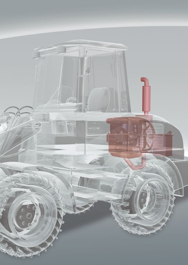
Questions and Answers on
the New EU Emission Legislation
for Mobile Machines
With the European Emission Regulation (EU) 2016/1628 –
Stage V published on 16 September 2016, the strictest
emission limits will in future apply to mobile machines
across Europe.
All machines which fall within the scope of Non-Road
Mobile Machinery (NRMM), i.e. agricultural, construction
and building material machinery, industrial trucks, cranes
and even inland waterway vessels, must further reduce
their exhaust emissions as of 2019.
The Directive shall apply throughout the EU as of
1 January 2017 and must be implemented as of 1 January
2019. Engines with a power range of 56 kW up to 130 kW
are exempt; their effective date is 1 January 2020.
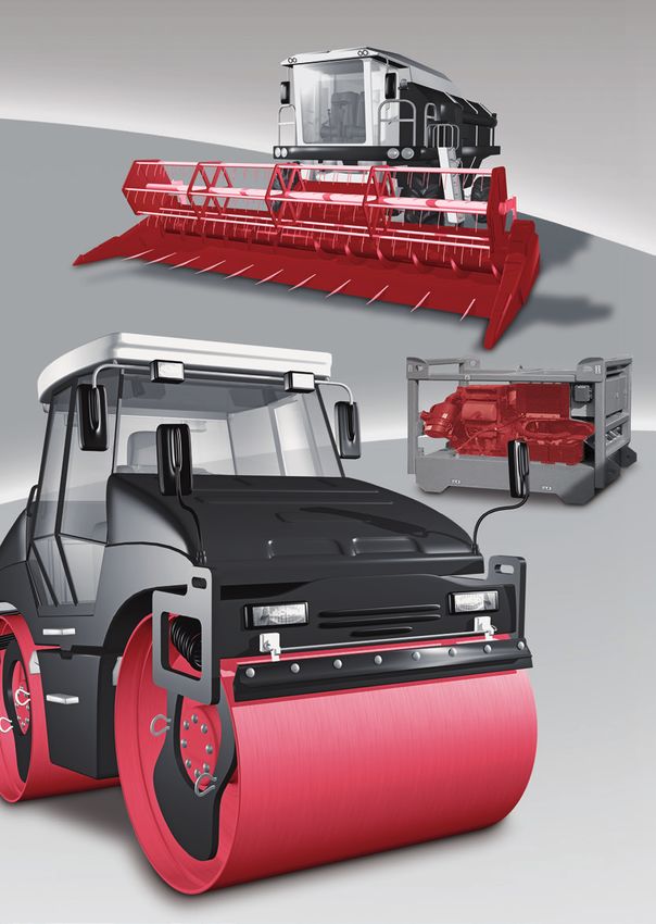
01 What are the key points of EU Stage V concerning
the legislation on reducing emissions further?
For the first time it concerns engines of all power ranges
which are used in the NRMM sector, i.e. from 0 kW up to
higher than 560 kW, both spark ignition engines (SI) and
compression ignition engines (CI). Moreover, this applies
equally to variable-speed and constant-speed engines.
The emission limits also apply to gas engines of all power
ranges.
In addition to the further reduction of particulate
matter (PM), nitrogen oxides (NOX), hydrocarbons (HC)
and carbon monoxide (CO), a particle number (PN) limit
EN 13.200.4 / 11.17
of 1 x 10¹² # /kWh is also being introduced for engines
with a power range from 19 kW up to 560 kW.
3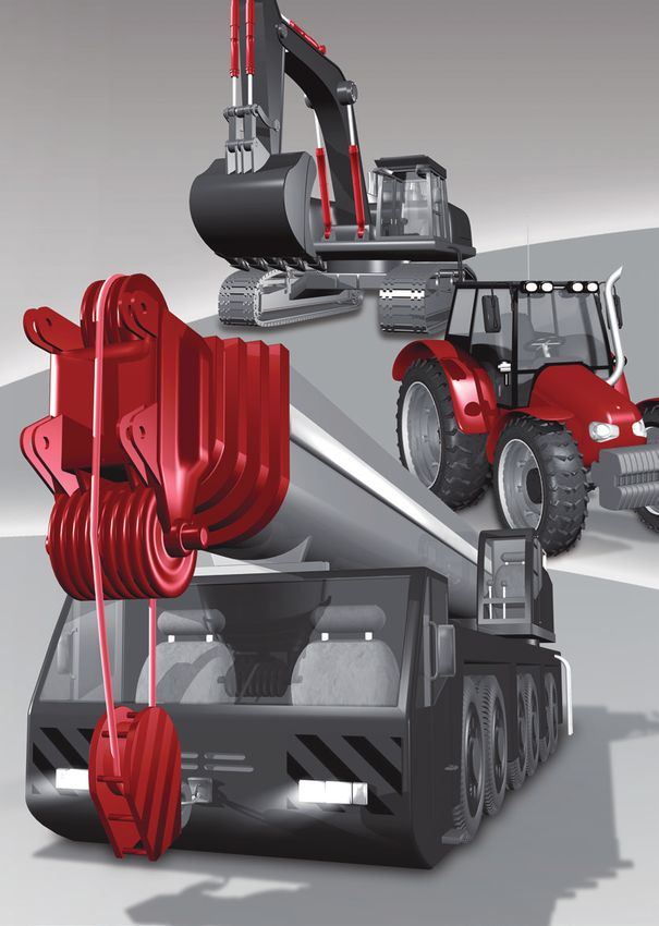
02   What is particulate matter (PM)?
                                                                                             05   What are hydrocarbons (HC)?

                           Particulate matter or particulates consist mainly of soot              Hydrocarbons are a family of compounds composed of
                           (carbon particles) and residues of lubricating oil.                    carbon and hydrogen, consisting basically of incompletely
                                                                                                  combusted fuel and oil residues. The concentration of
                                                                                                  hydrocarbons in diesel exhaust emissions is very low and
                                                                                                  can be further reduced through the use of high-quality

                      03   What does particle number (PN) limit mean, and what
                           does it mean for the use of engines?
                                                                                                  fuels, an efficient combustion process and an exhaust
                                                                                                  gas treatment system.

                           Soot particles result from combustion in engines with
                           an extreme lack of air. Diesel engines and also direct-
                           injection petrol engines are therefore referred to as “lean
                           burn engines” which generate soot particles of different          06   What is carbon monoxide (CO)?

                           sizes during operation.
                                                                                                  Carbon monoxide is a compound of carbon and oxygen
                           EU Stage V introduces a particle number (PN) limit of                  formed by incomplete combustion in the presence of
                           1 x 10¹² #/kWh for engines with a power range of 19 kW                 insufficient air.
                           to 560 kW which are used in NRMM. In order to comply                   Diesel engines operate with a large excess of air and
                           with the limit, the additional use of a particle filter will be        therefore normally only emit small quantities of carbon
                           mandatory.                                                             monoxide.

                      04   What are nitrogen oxides (NOX)?
                                                                                             07   What is carbon dioxide (CO2 )?

                           Nitrogen oxides consist of nitrogen monoxide (NO) and                  Carbon dioxide is one of two natural end products of
                           nitrogen dioxide (NO2). Nitrogen oxides are formed when                combustion; the other is water. CO2 is not toxic and the
                           the oxygen and nitrogen in air react under intense heat                quantity is directly proportional to the fuel consumption.
                           and high pressure during combustion.                                   CO2 contributes to the so-called greenhouse effect which
                                                                                                  impacts the climate.
EN 13.200.4 / 11.17

                                                                                                                                                               EN 13.200.4 / 11.17
     4                                                                                                                                                            5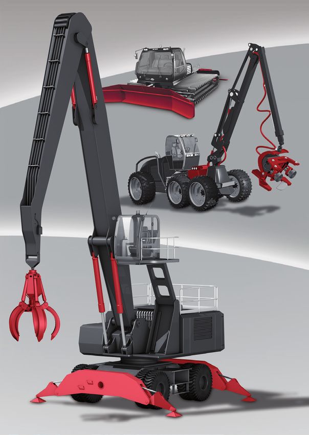
08   Are CO2 emissions regulated?

     No, CO2 is not regulated in the case of mobile machines,
     but governments, political parties and international and
     national bodies are placing increasing demands on, for
     example, the automotive, construction and agricultural
     industries to supply products with ever-lower CO2
     emissions.
     The onus is also on the users of these products to operate
     the machines in the most fuel-efficient way possible.

09   How can CO2 emissions from engines be reduced?

     The only way to reduce CO2 emissions is to lower the fuel
     consumption. Fuel-efficient engines and high-efficiency
     drive and hydraulic systems are therefore also important
     elements in the pursuit of lower CO2 emissions.

10   What is the difference in the specified emission levels
     of EU Stage IV compared to the future EU Stage V?

     For the first time, all engines with a power range of 0 kW
     to higher than 560 kW for use in NRMM are included in
     the EU Directive. In order to further reduce the levels of
     particulate matter (PM), the maximum particle number
     for engines between 19 kW and 560 kW is limited to
     1 x 10¹² # /kWh. All combustion engines (petrol, diesel,
     gas, etc.) are included, and it applies equally to both
     variable-speed and constant-speed engines.

                                                                  EN 13.200.4 / 11.17
                                                                     7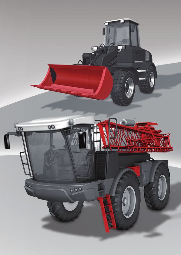
11       When does Stage V of the European Emission
                               Regulation (EU) 2016/1628 come into effect?

                               It was published in the Official Journal of the EU on                              All engines for Non-Road Mobile Machinery (NRMM) use that are
                               16 September 2016, and it is valid without having to be                            produced on or after 1 January 2019 must comply with EU Stage V,
                               implemented into national law. The emission regulation                             except for engines with a power range of 56 kW to 130 kW; their
                               shall apply as of 1 January 2017 and must be implemented                           effective date is 1 January 2020.
                               in European production areas as of 1 January 2019.

                       NOX     PM [g/kWh]                                                                        Applicable to all                             Applicable to all
                                      EU Stage I                                                             work machinery and units                     work machinery, machines,
                                       9.2 | 0.54                                                               with diesel engines                         units and combustions
                                                                                                               for the NRMM sector                         engines which are used
                       10.0    0.50                                                                                                                          in the NRMM sector
                                                                                                              from 19 kW to < 560 kW                          from 0 kW to 56 kW
                        8.0    0.40                                                                                                                         and 130 kW to > 560 kW
                                                          EU Stage II
                                                           6.0 | 0.20
                        6.0    0.30
                                                                               EU Stage IIIA
                                                                                 4.0 | 0.20                                                                     from 56 kW to 130 kW
                        4.0    0.20
                                                                                                            EU Stage IIIB
                                                                                                              2.0 | 0.025
                        2.0    0.10                                                                                               EU Stage IV             EU Stage V
                                                                                                                                   0.4 | 0.025            0.4 | 0.015
                           0
                                1998 1999 2000 2001 2002 2003           2004 2005 2006 2007 2008 2009 2010 2011 2012 2013 2014 2015 2016 2017 2018 2019 2020 2021 2022
                           0
                                                                                                                            0.4 | 0.01
                        2.0    0.10                                                                                         EURO VI
                                                                                               2.0 | 0.02
                                                                                                EURO V
                        4.0    0.20                                              3.5 | 0.02
                                                                                 EURO IV
                        6.0    0.30                 5.0 | 0.10
                                                    EURO III
                        8.0    0.40
EN 13.200.4 / 11.17

                                                                                                                                                                                       EN 13.200.4 / 11.17
                       10.0    0.50

                       NOX     PM [g/kWh]

     8                                                                                                                                                                                    9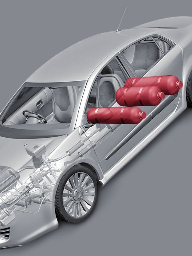
12   Will all new NRMM available for sale in 2019 and
                           beyond, in the market areas concerned, be equipped
                           with EU Stage V‑compliant engines?

                           Regulation 2016/1628 includes a transitional provision
                           and exception (§ 58) with a transition period of 24 months;
                           during this period it is still possible to put engines of a
                           previous emission stage on the EU market.
                           The transition period starts with the effective date for
                           placing Stage V engines on the market and essentially
                           applies to all engine categories. They must comply
                           with the previous emission stage and must have been
                           produced by the effective date of Stage V.
                           The machines with transition engines must have been
                           produced 18 months after the effective date of Stage V
                           at the latest and put on the market no later than 6 months
                           after that.
                           Engines with a power range of 56 kW ≤ P < 130 kW
                           are exempt. In this case, the effective date for Stage V
                           engines is 1 January 2020, followed by the applicable
                           24-month transition period.
                           The following exemptions apply:
                           Machine manufacturers with an annual production of
                           less than 100 units and manufacturers of mobile cranes
                           are granted a transition period of 36 months after the
                           effective date of Stage V. The machines / mobile cranes
                           must have been produced 30 months after the effective
                           date at the latest and put on the market within 6 months
                           after that.
EN 13.200.4 / 11.17

10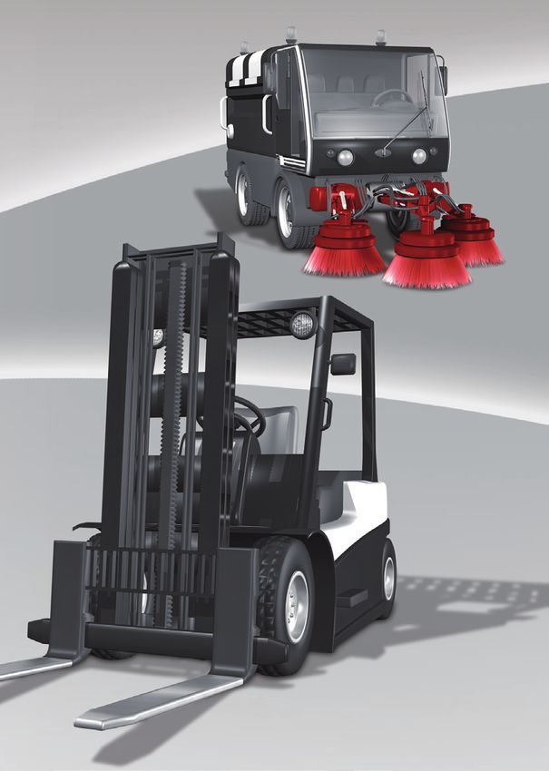
13   Are the regulated EU Stage V and US (EPA) Tier 4 Final               Diesel particulates (PM)  [g/kWh]
                           emission limits identical?                                     0.7
                                                                                                                             EU Stage I
                                                                                          0.6                                US Tier 1
                           Yes, when it comes to the limits for diesel engines they
                           are almost identical, based on the power range in which        0.5
                           the engine operates.
                           However: EU Regulation Stage V has a stricter limit of         0.4
                           0.015 for particulate matter (PM), and it also includes a
                           particle number (PN) limit of 1 x 10¹² #/kWh for the engine    0.3
                                                                                                     EU Stage IIIA           EU Stage II
                           power range of 19 kW to < 560 kW. The main difference                      US Tier 3               US Tier 2
                                                                                          0.2
                           between EU Stage V and US (EPA) Tier 4 Final is that
                           EU Stage V applies to all combustion engines (diesel,          0.1
                                                                                                     EU Stage IIIB
                                                                                                      US Tier 4i
                           petrol, gas) and that Tier 4f in the USA only applies to
                           diesel engines.
                                                                                                   1       2      3      4       5         6      7       8      9      10
                                                                                          EU Stage V     EU Stage IV                                  Hydrocarbons (HC) and
                                                                                                         US Tier 4f                            nitrogen oxides (NOx)  [g/kWh]

                      14   Will there be further requirements imposed by
                           governments at a future date regarding the reduction
                           of “non-road” machinery?
                                                                                          15       What technology options are available to meet the
                                                                                                   demands of the new EU Stage V regarding emission
                           The US (EPA) Tier 4 Final, the strictest emission                       limits?
                           regulation in the USA, came into force on 1 January 2014.
                           EU Emission Regulation Stage V, a much stricter and
                                                                                                   NOX and PM reduction can be achieved in several ways,
                           more comprehensive regulation, shall apply throughout
                                                                                                   each having both advantages and disadvantages.
                           Europe as of 1 January 2017 and must be implemented
                                                                                                   For example, in-engine NOX reduction always leads to
                           as of 1 January 2019.
                                                                                                   higher PM emission levels, and conversely, in-engine
                           From today’s perspective, it is reasonable to assume that
                                                                                                   reduction of PM leads to higher NOX emissions.
                           there will not be another, even stricter emission regulation            Optimisation of fuel injection and air supply, including
                           in the near future – neither in the USA nor in the EU.                  different EGR (Exhaust Gas Recirculation) configurations
                           But rather, other countries or continents will adopt either             (cooled / non-cooled etc.), and various exhaust gas
                           one or the other regulation.                                            treatment technologies, including soot particulate filters
                                                                                                   and SCR (Selective Catalytic Reduction) technology are
                                                                                                   all tools used for NOX and PM reduction. In order to be
EN 13.200.4 / 11.17

                                                                                                                                                                                EN 13.200.4 / 11.17
                                                                                                   able to meet the required particle number (PN) limit,
                                                                                                   a soot particulate filter must be used.

12                                                                                                                                                                                 13
16   How does SCR technology work? ...
                                                                                       18   Will EU Stage V solutions be based on the existing
                                                                                            engine platforms or will a new design be required?
                           Selective Catalytic Reduction (SCR) is a technology
                           where a reagent is injected into the exhaust gas flow and        Mobile machines are generally powered by modern
                           mixed in a catalytic converter.                                  high-volume production engines. These engine platforms
                           This reduces the NOX to harmless nitrogen and oxygen.            have been designed from the outset to cope with the
                           The reagent is a mixture of 32.5 % urea and 67.5 %               higher internal loads arising from the new performance
                           water and in Europe is commercially known as AdBlue®.            requirements of EU Stage V. Some design changes will,
                           Depending on the engine load factor, the consumption             however, be introduced in order to further enhance the
                           of AdBlue® is approx. 4 – 5 % of the diesel fuel usage.          performance of the engines.

                           The basic engine must, in any case, be fine-tuned to             It is important to mention here that the engine platforms
                           minimise engine-out PM emissions as required by the              that are normally used for EU Stage V applications are
                           EU Stage V emission regulations.                                 used in road vehicles by prestigious manufacturers and
                                                                                            have already undergone more than 2,000,000 km of
                                                                                            real-world testing.

                      17   …and DPF technology?

                           The Diesel Particulate Filter (DPF) is a device in which
                           the particulates are collected and then oxidised by
                                                                                       19   Are there any other factors that influence the design
                                                                                            of the machines?
                           passive or active regeneration. Advanced electronic
                           control of the process is necessary to ensure effective          The larger space requirement of the additional systems
                           PM removal in all engine duty cycles of any type.                in the exhaust system means that the existing space
                                                                                            must be used very efficiently or new space must be
                           In addition, the basic engine must be fine-tuned to              created by reducing other components (e.g. tanks).
                           minimise engine-out NOX emissions to meet the NOX
                           levels required by law. Ultra-low sulphur fuels and
                           low‑ash lubricating oils are a must for these DPF
                           technologies to function properly.
EN 13.200.4 / 11.17

                                                                                                                                                        EN 13.200.4 / 11.17
14                                                                                                                                                         15
Practical Implementation
                      of the Emissions Directive

                      By the end of 2010:           Since 2011:                      Since 2014:                  From 2019:
                      Tier 3 / EU Stage IIIA        Tier 4 Interim / EU Stage IIIB   Tier 4 Final / EU Stage IV   EU Stage V

                                                               Only diesel engines                                    All combustion engines

                      - Common rail system          -	Two-stage turbocharging       - Common rail system         - SCR system with AdBlue®
                      -	Single-stage                 with intercooler               -	Two-stage turbocharging   - Use of soot particulate filters
                        turbocharging               - Diesel particulate filter        with intercooler           -	Obligation of the engine
                                                    -	Externally cooled EGR         - Externally cooled EGR        manufacturer to monitor
                                                      (Exhaust Gas Recirculation)    - SCR system AdBlue®           the emission limits in the
                                                    - SCR system AdBlue®                                            final application (e.g. with
                                                                                                                    PEMS – Portable Emission
                                                                                                                    Measurement System)
                      Development of costs

                               100 %                             +40 %                            +25 %                        +10 %
EN 13.200.4 / 11.17

                                                                                                                                                      EN 13.200.4 / 11.17
                      Installation space required

                               100 %                             +40 %                            +25 %                         +0 %

16                                                                                                                                                       17
HYDAC’s Answers
to Energy-Saving,
Emissions Reduction and
Additional Space Requirements
In its range of products HYDAC holds numerous answers
to today’s questions on environmental protection, reduction
of emissions, and energy and fuel-saving.
Whether cars, commercial vehicles or mobile machinery –
the demands made on the most up-to-date components
and systems and their future development are practically
identical.

HYDAC develops and supplies
Components, Systems and Support                         Page

For Diesel Filtration                                     20

For Cooling Systems (combination coolers, fan drives)     21

For Space Requirement Optimisation:
Cooler / Filter / Tank Combinations                       24
Plastic Tank Systems                                      25

Support / System Optimisation                             28

For Hydraulic Hybrid Technology                           30

For Hydraulic Start / Stop Technology                     31

For Total Energy Optimisation                             32

For Gas Tanks (CNG / LPG)                                 36

For Diesel Particle Filters                               36

                                                                EN 13.200.4 / 11.17
For SCR Technology (Selective Catalytic Reduction)        38

                                                                   19
HYDAC Components...
... for Diesel Filtration ... for Cooling Systems
HYDAC Diesel PreCare Combination Cooler CMS
Diesel filtration and The Emissions Directive is entering its
2-stage water separation next phase, and the implementation of
Manual water discharge – BC EU Stage V is just around the corner.
(BestCost Design) – the conventional, It is therefore necessary to recheck
operator-dependent solution whether the cooler must be adapted to the
amount of heat to be dissipated from the
Fully automatic discharge – HT drive engine. This will influence the size
Plug &Play (HighTech Design) – the of the cooler and the installation space,
innovative solution for fully automatic which is limited in mobile machinery.
dewatering, independent of the operator, It must therefore be used efficiently and
even during suction-side operation Mobile cooler, folding version
intelligently.
Suction side pre-filter
Protects all the pumps and With the mobile CMS cooler range and
components in the fuel system further optional components, HYDAC
HYDAC HDP BC and HT
from water and contamination offers excellent combination and
integration options. Several cooling
Environmentally friendly due to circuits can thus be covered:
incinerable filter elements
Charge air cooling (CAC)
Longer service life and
increased machine availability Coolant cooling (RAD)
Oil circuits: transmission, hydraulics
New: HDP BC 600 Fuel cooling
Diesel pre-filter including electrical Mobile cooler for excavator A variety of equipment can be
pump – with multiple functions: applications integrated to achieve a compact design
Venting the pipe and customised solutions:
Booster for improving Cooler / filter / tank combinations
engine start-up performance with integrated fan drive
or Integrated pressure bypass valve (IBP)
As continuous pump for unloading or thermal pressure bypass valve (IBT)
the engine’s low pressure pump Temperature sensors
EN 13.200.4 / 11.17
EN 13.200.4 / 11.17
High service life, as pump is brushless Fan control
Tank disinfection thanks to innovative Combined in one component, they can
Biomicron® filter media technology and make a significant contribution to reducing
HDP BC 600 and Biomicron®
option of offline filtration installation space.
Mobile cooler for concrete pump
20 21HYDAC Components...
... for Cooling Systems
Fan Drives
The efficiency of a cooler depends largely
on the fan control. Various options are
used for DC and hydraulic fan drives:
Electronic speed control ESC
Hydraulic fan control B-BM-LSTA
Electronic speed control for DC Temperature bypass TB
drives with optional reversing
function Proportional valve for continuous control
of the fan speed
This means that the fan speed is tailored
directly to the required cooling capacity
and just sufficient power is supplied to the
fan as is immediately required.
As an option, most controls can also be
supplied with a reversing function for the
rotation direction, to “purge” the cooler
of coarse contamination, e.g. fibrous
material, paper or major plant residues).
Mobile cooler with DC drive and ESC
for loading crane applications
Fan control block
EN 13.200.4 / 11.17
flanged on a hydraulic motor
22HYDAC Components...
... for Space Requirement
Optimisation
Cooler / Filter / Tank Plastic Tank Systems
Combinations Plastic tanks are primarily used where
In order to implement the Emissions installation space is limited or in order to
Directive, additional installation space reduce weight. This means that complex,
for the engine is required. customised tank designs are frequently
Integrating the filters, cooler and tank in required in addition to our standard
one space-saving and customised unit designs.
that is optimised for the installation space
allows multiple functions to be combined. Advantages:
Hoses and pipes can be shortened or Improved component cleanliness, since
eliminated. Since the plastic tank also plastic tanks are very clean following
functions as a fan casing, it could be production
designed to optimise air flow.
All in all, we have a compact, powerful Improved use of the existing installation
and low-noise module with charge air, space due to optimised designs
oil and coolant cooler, with the oil tank Inexpensive, since the costs depend on
integrated with all functions such as the tank volume and not design complexity
fluid level gauge, breather filter and
return line suction filter. Lower weight
No risk of corrosion and therefore
Advantages: resistant to aging
Improved use of the existing installation Fewer assembly and test requirements
Cooler / filter / tank combination space due to optimised design
with hydraulic fan drive for
since system is supplied with all add-on
mobile applications Cost-effective and compact design components (including air breather and
since integration of filters and coolers return line filters, oil level gauges,
eliminates the need for pipework standard fittings, clamping bands, etc.)
Reliable heat regulation and optimum
cooling performance despite reduced
amounts of cooling water
Guaranteed system cleanliness
EN 13.200.4 / 11.17
EN 13.200.4 / 11.17
Easy to service Problem:
If inadequately designed, smaller hydraulic tanks can be a cause
of air in oil (see following pages).
Filter / tank combination in
industrial trucks
HYDAC Support: HYDAC offers a wide range of support
to avoid air in the hydraulic system (see page 28).
24 25HYDAC Tank Optimisation – Motivation
Current requirements
for mobile machines:
Emission standards
Energy efficiency
Power density
Low life cycle cost
Noise control
Vibration protection in the workplace
Changes in the design
Performance
of both machine
problems
and hydraulics
RISK: Air in the hydraulic system Effects of air
Problems of installation space
in the hydraulic system
Efficiency losses in pumps
Cavitation damage to components
Accelerated oil ageing /
micro-dieseling effect
Dynamic operating
Consequence: e.g. changes to hydraulic tank: problems / increased
EN 13.200.4 / 11.17
EN 13.200.4 / 11.17
Tank volume compressibility
Tank geometry Noise generation
Dwell time Increase in temperature
26 27HYDAC Support / System Optimisation
Intelligent System Optimisation
for Air Removal
We use the following tools to develop the best individual solutions
for your system:
Many years’ experience in the field of intelligent system optimisation
for air removal and stimulating exchanges of information in this area In the HYDAC FluidCareCenter, our most experienced fluid technology
specialists work on application-specific solutions
Customised test rigs and measurement technologies analyse the air removal
on subsystems and develop the optimum solution for your application Air content (1 = 100 %)
0.1
Qualified engineers measure air removal from complete systems
using field instruments
0.01
Qualified engineers find and rectify any sources of air inclusion
0.001 t=2s t = 10 s t = 60 s t = 300 s
CFD flow simulations to find solutions
Individual, space-saving complete tank systems (see also page 25) Multiphase bubble flow simulation in the tank
to prevent air inclusion in your system
Return Line Filter for Tank Optimisation
In the field of tank optimisation with regard to
Tank Optimisation – HYDAC Platform degassing, HYDAC has succeeded in creating a filter
series (in-to-out) which not only reduces the amount
Field tests of air in the oil due to its specific degassing concept,
but also allows for a significantly smaller tank design.
For the OEM this means considerable cost savings
Laboratory (less oil) as well as less material usage and space
Technology requirements for the hydraulic tank. The filters are
tests
also equipped with quality protection features which
do not permit operation with external elements.
The intelligent QP version is supported by our HYDAC clogging indicator
(HPT500) which identifies the use of original filter elements and displays an
Simulation Experience error message if external elements are used.
Advantages:
Longer oil service lives due to active degassing
EN 13.200.4 / 11.17
EN 13.200.4 / 11.17
Quality protection ensures the use of original filter elements
Tank optimisation Lower ∆p thanks to innovative Helios® fold geometry
Technology platform Lower maintenance costs (smaller tank / less oil)
28 29HYDAC Components...
... for Hydraulic ... for Hydraulic
Hybrid Technology Start / Stop Technology
In many mobile machines, the typical work In the car industry, electrical start / stop
cycles involve phases of high dynamics systems are already established technology
with pronounced load peaks. This makes which allow considerable fuel savings to be
Traction drive it possible to save fuel by implementing made. In mobile machinery, automatically
hydraulic hybrid systems on the machines. switching off the drive engine when it is
idling is also a source of major potential
In all hydraulic hybrid systems, hydraulic Diesel Pump / Control
savings, depending on the particular
Diesel accumulators are used to store energy engine motor block
engine application.
temporarily. Our decades of experience
in designing, developing and producing In mobile machinery, existing hydraulic
hydraulic accumulators combined with our Structure of a hydraulic infrastructures can normally be used to
simulation expertise form the foundation start / stop system
Example of parallel hybrid structure realise start / stop functionalities.
of successful hybrid projects performed in For example, work-hydraulics pumps
close collaboration with the customer.
in a modified form can also be used as
With our valve variants, we can create hydraulic motors. After an automatic “idle
customised control blocks that minimise stop”, the diesel engine is restarted by the
pressure loss. Tried and tested sensors, working hydraulics pump in motor operation
safety devices and fastening technology mode. The energy required for this is
are other typical components for our provided by a hydraulic accumulator that
hybrid systems. was charged “in the background” during
HYDAC’s hybrid range is rounded off with normal machine operation.
innovative hybrid solutions, such as double
piston accumulators, that can be used for The hydraulic start / stop solutions generally
parallel hybrid concepts and also for load provide quicker starting processes than
Example of load compensation compensation. Example of a electrical systems, which above all
“control block + accumulator” solution improves operator acceptance.
Bladder, piston and diaphragm Since HYDAC has extensive experience in
accumulators and nitrogen bottles hydraulic control blocks and is a specialist
(back-up) in hydraulic accumulator solutions, we have
Extensive valve portfolio what it takes to be the perfect development
Control blocks / hybrid modules partner for hydraulic start / stop solutions.
Safety devices
Sensors and control devices
EN 13.200.4 / 11.17
EN 13.200.4 / 11.17
(with SIL 2 / 3 and / or PL d)
Mounting technology
(various clamps and consoles)
Motor downsizing with hybrid module
30 31HYDAC Components...
... for Total Energy
Optimisation
Sensors Universal Mobile Controller
In order to comply with the directives on
HY-TTC 500 / 90 / 60 / 30
the reduction of engine exhaust emissions The HY-TTC family meets all technical require-
for mobile machines, hydraulic systems are ments for modern automotive electronics in
today being developed with particular focus the off-highway sector. It is part of a complete
on the most efficient use of energy. and compatible product family and is protected
by a robust and extremely compact housing
Pressure transmitters and switches HYDAC supplies various sensors specially
specially designed for the off-highway vehicle
designed for use in harsh conditions in industry.
mobile hydraulics: pressure transmitters,
electronic pressure switches and speed, Performance features:
inclination, temperature, flow rate, angle Functional safety PL d / SIL 2
and distance sensors. Comprehensive I/O set, up to 98 I/O (38 PWM)
Functional Safety They are particularly well suited to complex
PL d
SIL 2 open and closed-loop control tasks in Robust die-cast aluminium housing
electro-hydraulic systems for mobile
Linear position / distance sensors machinery. I/O Expansion Modules
Performance features:
HY-TTC 48X / 48XS / 30X / 30XS
Available with a variety of output signals, The HY-TTC series of I/O expansion modules
connectors and fluid port connection provides an outstanding power balance
options combined with extremely compact design.
They provide a simple extension of on-board
Functional Safety
Robust design electronics. The communication and integration
PL d
takes place via CANopen according to CiA
SIL 2 ECE type approvals
DSP 401. It enables inputs and outputs to be
Inclination and angle sensors Good EMC characteristics configured and parameterised via the control
configuration of the available controller in a
Approval for explosive atmospheres Functional Safety
PL c / d
SIL 2
simple and uncomplicated way.
Separate product portfolio, Performance features:
especially for applications with
increased functional safety (SIL 2, PL d) Up to PL c
Freely configurable Node-ID via pin
EN 13.200.4 / 11.17
EN 13.200.4 / 11.17
Functional Safety
PL d
Up to 48 I/O with up to 8 PWM outputs
SIL 2
Robust and very compact housing
Sensors for increased functional
safety requirements (e.g. PL d, SIL 2)
32 33HYDAC Components...
... for Total Energy
Optimisation
Load-Sensing Accumulator
Switching Valve Charging Switch
Load-sensing generally refers to load- HYDAC accumulator charging valves
sensing hydraulic controls. In this case control the charging of the hydraulic
the block is designed to charge an accumulator within an adjustable
accumulator in the brake circuit quickly. switching range.
When the accumulator is full, the valve is
closed and when it is drained, the valve The combination of accumulator
to the pump opens and the full pump and accumulator charging valve
pressure acts on the pump’s LS line. means that pumps and motors on
The pump’s displacement angle now oil-hydraulic systems with fluctuating
switches to maximum in order to charge flow requirements can be downsized.
the accumulator quickly. This saves money and energy, and
unnecessary heat generation is also
A built-in pressure relief valve protects avoided.
the pump. An additional orifice dampens
the load sense pressure signals. Application examples
for mobile machinery:
Advantages: In the brake circuit
Pump protection built into the block For supplying the emergency steering
Optimum damping of the system
through use of bypass orifice Advantages:
Accumulator charging as required Simple and optimum system adaptation
through the use of valves with various
fixed switching pressure differentials
(12, 16, 21 %)
Shut-off pressures are user-adjustable
Low ∆p characteristics
The accumulator cannot discharge
unexpectedly because the poppet
valves are leak-free
EN 13.200.4 / 11.17
EN 13.200.4 / 11.17
34 35HYDAC Components...
... for Gas Tanks
Oil Separator
for Natural Gas Vehicles
CNG (Compressed Natural Gas) may be
contaminated with particles and oil during
refuelling. Our 2-stage low pressure oil
separator removes particles and oil, thus
protecting valves and injectors in the CNG
system.
Mounting Technology
for Gas Tanks
TÜV certified, patented gas tank mounting
clamps with quick release fastenings
“Multi” swivel bolt band clamp
... for Diesel Particulate Filters
Mounting Technology
The continued development of the
successful “Multi” swivel bolt band clamp
made from high-quality stainless steels.
Specifically designed for high dynamic
loads, thermal stresses, changes in
diameter and the effects of strong
forces – already successfully applied in
EN 13.200.4 / 11.17
series by well-known manufacturers in
the mobile industry.
36HYDAC Components...
... for SCR Technology
AdBlue® Filtration
AdBlue® is an aqueous 32.5 % urea
solution which starts freezing at -11 °C
The filter is used as a suction filter
upstream of the pump in the AdBlue® tank
It is designed as a “lifetime filter”
which is also resistant to freezing cycles
Worldwide emission regulations up to 2020
AdBlue® Conveyor
System on the Basis
of a Magnetic Pump
Self-priming
Suction height: 3 m
Anti-freezing
Integrated heater
Integrated AdBlue® quality sensor
Filter (20 µm, contamination
retention capacity 100 g)
EPA Tier 4 interim / EU Stage IIIA
EPA Tier 4 final / EU Stage IIIB
Technical data:
Q = 120 l/h
EPA Tier 2 / EU Stage II
Others / no regulation
p = 2.5 bar
Japan MDE / MLIT
U nom = 24 V
I = 6.5 A
EU Stage V
EN 13.200.4 / 11.17
EN 13.200.4 / 11.17
38 39HYDAC INTERNATIONAL Industriegebiet
GMBH 66280 Sulzbach / Saar
Germany
Tel.: +49 6897 509-01
Fax: +49 6897 509-577
E-mail: info@hydac.com
Internet: www.hydac.com
EN 13.200.4 / 11.17You can also read