RA16PA/RA4PA MEDUSA PREAMPS - HARDWARE REFERENCE - UPDATED 2021-10-20 - TUCKER-DAVIS TECHNOLOGIES
←
→
Page content transcription
If your browser does not render page correctly, please read the page content below
RA16PA/RA4PA Medusa PreAmps
                  Hardware Reference

                       Updated 2021-10-20
RA16PA/RA4PA Medusa PreAmps | 2 © 2016-2021 Tucker-Davis Technologies, Inc. (TDT). All rights reserved. Tucker-Davis Technologies 11930 Research Circle Alachua, FL 32615 USA Phone: +1.386.462.9622 Fax: +1.386.462.5365 Notices The information contained in this document is provided "as is," and is subject to being changed, without notice. TDT shall not be liable for errors or damages in connection with the furnishing, use, or performance of this document or of any information contained herein. The latest versions of TDT documents are always online at https://www.tdt.com/docs/
Table of Contents | 3

Table of Contents

 RA16PA/RA4PA Medusa PreAmps
  Medusa Overview                                         4
  Medusa Features                                         5
    Analog Acquisition Channels                           5
    Clip Warning Lights                                   5
    Power Light                                           5
    Headstage Connector                                   6
    Base Station Connector - To Base                      6
    Power                                                 7
    LEDs                                                  7

  Power Requirements                                      7
  RA16PA/RA4PA Technical Specifications                   8
    Pinout Diagrams                                       8
RA16PA/RA4PA Medusa PreAmps | 4
RA16PA/RA4PA Medusa PreAmps
Medusa Overview
The Medusa Preamplifiers are low noise digital bioamplifiers and are available with either PCM
or Sigma-Delta ADCs. The system amplifies and digitizes up to 16-channels of analog signal at
a 24.414 kHz sampling rate. The amplified digital signal is sent to the base station via a
noiseless fiber optic connector.
• Digitizes either four or 16 channels at acquisition rates of approximately 6, 12, or 25 kHz.
• Connects to the headstage via a DB25 connector.
• Powered by a Lithium-ion battery that provides 20 hours of continuous data acquisition in
16-channel mode and 30 hours of operation in 4-channel mode.
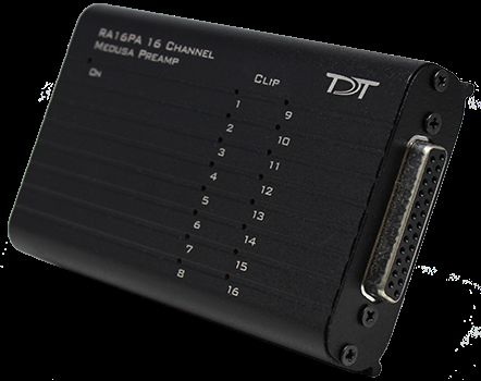
• Clip warning lights indicate when any signal is -3db from the preamplifier's maximum
voltage input.RA16PA/RA4PA Medusa PreAmps | 5 Medusa Features Analog Acquisition Channels The RA16PA and RA4PA standard Medusa Preamplifiers acquire signals using 16-bit PCM ADCs, which provide quality acquisition with minimal delay. The RA16SD and RA4SD use Sigma-Delta ADCs, which have several characteristics that improve signal quality. Oversampling of the signal before conversion removes aliasing of high frequency RF signals. RA16SD testing indicates that signals greater than 150% of the Nyquist frequency are removed from the signal. This allows users to acquire at lower sampling rates (6 kHz) without worry of significant aliasing. In addition, each converter also has a two pole anti-aliasing filter (12 dB per Octave) at 7.5 kHz. However, the sigma-delta ADC's have a fixed group delay of 20 samples (compared to four samples for the RA16PA). When using the RA16SD this group delay must be taken into account when the data is displayed or acquired (for example, adding a SampDelay to the RPvdsEx circuit). Clip Warning Lights When the input to a channel is greater than -3db from the preamplifier's maximum voltage input, a light on the top of the amplifier is illuminated. The first column of lights corresponds to channels 1-8 and the second column corresponds to channels 9-16. The clip warning light indicator can be turned off by flipping a switch on the end of the amplifier. Power Light The power light is in the top corner of the amplifier. It is illuminated when the device is on. It flashes quickly if the battery is low. It flashes slowly while the battery is charging. Note: The flashing LED indicator is only available when the amplifier is powered on and connected to a powered base station.
RA16PA/RA4PA Medusa PreAmps | 6

Headstage Connector

 The headstage connector is a 25-pin (16-channel) connector. Information on the pin inputs is
 provided with the technical specifications.

Base Station Connector - To Base

 Use the provided fiber optic pair (white connectors) to connect the To Base port on the
 preamplifier to the optical input port on the base station.

 The duplex fiber optic cable has identical one-piece connectors at each end. There is a V-
 shaped groove on one side of the connector and a raised rectangle on the other. As shown in
 the image above, plug the connector into the RZ6 port with the raised rectangle side up. Plug
 the connector into the preamplifier with the V-shaped groove up.
RA16PA/RA4PA Medusa PreAmps | 7

                                 Medusa PreAmp Connection Diagram

Power

 A switch on the back powers up the amplifier. The fiber connector at the right will be
 illuminated when the amplifier is on.

LEDs

 This switch turns the clip warning lights on top of the amplifier on or off.

Power Requirements
 The Lithium-ion batteries charge in four hours. Keeping the battery charger connected to the
 amplifier does not affect the battery life. However, the charger will significantly increase the
 noise of the system if it is plugged in while an experiment is running. A 6 volt battery charger is
 included with the amplifier. The charger tip is center negative. If it is necessary to replace the
 charger make sure that the power supply has the correct polarity.

 The Li-ion battery supplied with the system cannot be removed. If battery life longer than 30
 hours is required, an external battery pack can be connected to the voltage inputs of the
 charger. TDT recommends a 6 Volt (minimum) to 9 Volt (maximum) battery, such as lead acid
 batteries used for motorized wheel chairs. See Tech Note #0256 for more information.
RA16PA/RA4PA Medusa PreAmps | 8
RA16PA/RA4PA Technical Specifications
Includes specifications for the RA4PA, RA16PA, and RA16SD Medusa Preamplifiers.
A/D RA4PA: 4-channels 16-bit PCM
RA16PA: 16-channels 16-bit PCM
RA16SD: 16-channels 16-bit sigma-delta
Sample Rate 6, 12, or 25 kHz
Maximum Voltage In RA4PA and RA16PA: ± 4 millivolts
RA16SD: ± 5 millivolts
Frequency Response 3 dB 2.2 Hz - 7.5 kHz
Highpass Filter 2.2 Hz
Anti-Aliasing Filtering RA4PA and RA16PA: 7.5 kHz (3 dB corner, 1 st order, 6 dB per octave)
RA16SD: 7.5 kHz (3 dB corner, 2 nd order, 12 dB per octave)
S/N (typical) RA4PA and RA16PA: 60dB
Input Referred Noise rms 3 microvolts bandwidth 300 - 3000 Hz
6 microvolts bandwidth 30 - 5000 Hz
Group Sample Delay RA4PA and RA16PA: NA
RA16SD: 20 Samples
Input Impedance 100 kOhms
Power Requirements 500 mAmps while charging, 60 mAmps once charged
Battery Li-ion Battery 1950 mAh, 20-25 hours between charges.
1000 cycles of charging, not removable by user
Charger 6-9 Volts DC, greater than 500 mAmps, center negative
Fiber Optic Cable 5 meters standard, maximum cable length 12 meters
Pinout Diagrams
16- and 4-channel pinouts (all models built after 2002):RA16PA/RA4PA Medusa PreAmps | 9 Pin Name Description Pin Name Description 1 A1 Analog Input Channels 14 V+ Positive Voltage (+1.4V) 2 A2 15 GND Ground 3 A3 16 GND Ground 4 A4 17 V- Negative Voltage (-1.4V) 5 Ref Reference 18 HSD Headstage Detect 6 DNC Do Not Connect 19 HSD 7 A5 Analog Input Channels 20 A6 Analog Input Channels 8 A7 21 A8 9 A9 22 A10 10 A11 23 A12 11 A13 24 A14 12 A15 25 A16 13 DNC Do Not Connect
You can also read