TCS 003 - 2019 Ramp Control/Metering Signs Specification for - April 2019 Rev: A - VicRoads
←
→
Page content transcription
If your browser does not render page correctly, please read the page content below
TCS 003 - 2019

Specification for

Ramp Control/Metering Signs

April 2019
Rev: A

Page 1 of 72

TCS 003 - 2019                                           Rev. A

     TCS 003 - 2019

                                                           Foreword

                                                           This specification has been developed by VicRoads. It is
                                                           one of a number of technical specifications, and
                                                           associated standard drawings, which set out the
                                                           requirements for roadside ITS devices, traffic signal
                                                           equipment and other electrical equipment and associated
                                                           devices and control systems.

                                                           This specification is intended for use in all relevant
                                                           works undertaken by or on behalf of VicRoads.

                                                           VicRoads Standard Drawings, Specifications and
                                                           Guidelines are available for downloading from VicRoads
                                                           website at the following address under ‘Tenders &
                                                           Suppliers’, http://www.vicroads.vic.gov.au/itsspecs

                                                           Specification updates. VicRoads specifications and
                                                           associated standard drawings are subject to periodic
     COPYRIGHT                                             review. To keep the specifications up to date,
                                                           amendments or new editions are issued as necessary. It
     © Road Corporation trading as VicRoads. All           is therefore important for users of VicRoads
     rights reserved.                                      specifications to ensure that they have the latest version
                                                           and associated amendments.
     This document remains the property of VicRoads.
     No part of this document may be reproduced or
     copied in any form or by any means, electronic or     Road Operations
     mechanical, including photocopying, without the       60 Denmark Street Kew 3101
     written permission of VicRoads
                                                           Phone: (03) 9854 2103      Fax: (03) 9854 2319

Page 2 of 72                                 Ramp Control/Metering Signs
Rev. A                                   TCS 003 - 2019

                                    PREFACE
A. TELECOMMUNICATIONS EQUIPMENT

A.1   All telecommunications equipment shall comply with relevant requirements of the Australian
      Communications and Media Authority (ACMA). Such equipment shall be labelled with a
      Regulatory Compliance Mark.

B. CHANGES TO THIS SPECIFICATION

B.1   The main changes to this specification from previous versions are listed below:

      •   Updated VicRoads template
      •   Corrected referencing
      •   Updated sign requirements
      •   New requirements for device warranty
      •   New section for installation requirements

                                      Ramp Control/Metering Signs                          Page 3 of 72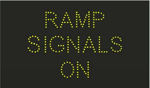
TCS 003 - 2019                             Rev. A

                                     Revision History

Version Revision        Date            Author                      Description

 2002            3   March 2002            TTI

 2003            4    Aug 2003             TTI

   5                  June 2011           RUS                          Revision

                                                     Editorial fixes, revised sign layouts, revised
   5             B   August 2011          RUS
                                                                         figure.

   5             C   October 2011         RUS                   Clarification of LED’s

                                                      Revised operation and control, changes to
 2016            A   March 2016            RO
                                                                     sign types
                                                     Revised and updated. Remove requirement
 2019            A    April 2019           ITS       for visors. Addition of installation section
                                                             and warranty requirements.

Page 4 of 72                      Ramp Control/Metering Signs
Rev. A                                                      TCS 003 - 2019

                                                               Contents
SECTION 1 - SCOPE AND GENERAL ............................................................................... 8
  1.1    SCOPE .................................................................................................................................... 8
  1.2    GENERAL .............................................................................................................................. 9
    1.2.1     Ramp Control/Metering Sign - RC1 ............................................................................... 9
    1.2.2     Ramp Metering Sign – RC2 ............................................................................................ 9
    1.2.3     Ramp Control Sign – RC3 .............................................................................................. 9
    1.2.4     Ramp Control Sign Designations .................................................................................. 10
  1.3     INTELLECTUAL PROPERTY ........................................................................................... 13
  1.4     ACRONYMS ........................................................................................................................ 13

SECTION 2 – RELATED SPECIFICATIONS AND DRAWINGS ................................. 14
  2.1        AUSTRALIAN STANDARDS ............................................................................................ 14
  2.2        VICROADS SPECIFICATIONS AND DRAWINGS ......................................................... 14
  2.3        ADDITIONAL SPECIFICATIONS AND DOCUMENTS.................................................. 15

SECTION 3 - RC1 RAMP CONTROL / METERING SIGN ........................................... 16
  3.1        GENERAL ............................................................................................................................ 16
  3.2        DISPLAY REQUIRMENTS ................................................................................................ 16

SECTION 4 - RC2 RAMP METERING SIGNS ................................................................ 19
  4.1        GENERAL ............................................................................................................................ 19
  4.2        RC2-A DISPLAY REQUIRMENTS .................................................................................... 19
  4.3        RC2–C DISPLAY REQUIREMENTS ................................................................................. 21

SECTION 5 - RC3 RAMP CONTROL / FREEWAY CONDITION SIGNS .................. 22
  5.1        GENERAL ............................................................................................................................ 22
  5.2        RC3-A DISPLAY REQUIRMENTS .................................................................................... 22
  5.3        RC3-B DISPLAY REQUIRMENTS .................................................................................... 24
  5.4        RC3-C DISPLAY REQUIRMENTS .................................................................................... 24

SECTION 6 - OPERATION AND CONTROL .................................................................. 26
  6.1        GENERAL ............................................................................................................................ 26
  6.2        SIGN CONTROL PERFORMANCE AND CAPABILITY................................................. 27
  6.3        SIGN CONTROLLER (SC) ................................................................................................. 28
  6.4        ADMINISTRATION AND CONFIGURATION TOOL ..................................................... 28
  6.5        RESET .................................................................................................................................. 33
  6.6        SIGN CONTROLLER PARAMETER DEFAULT SETTINGS .......................................... 33
  6.7        ETHERNET .......................................................................................................................... 34
  6.8        RMS PROTOCOL FOR SIGN CONTROL ......................................................................... 35
  6.9        OTHER PROTOCOLS ......................................................................................................... 35
  6.10       HARDWARE SERIAL PORTS: .......................................................................................... 36
  6.11       DIAGNOSTIC FUNCTIONS ............................................................................................... 37
  6.12       MONITORING, FAULT LOGGING AND REPORTING .................................................. 38
  6.13       LOCAL CONTROL ............................................................................................................. 39
  6.14       REMOTE CONTROL .......................................................................................................... 40
  6.15       FALL-BACK SYSTEM ....................................................................................................... 40
  6.16       DISPLAY TEST PATTERNS .............................................................................................. 40
  6.17       FIRMWARE UPGRADE ..................................................................................................... 41

                                                         Ramp Control/Metering Signs                                                  Page 5 of 72
TCS 003 - 2019                                                     Rev. A

SECTION 7 - OPTICAL REQUIREMENTS ..................................................................... 42
  7.1       PHOTOMETRIC REQUIREMENTS .................................................................................. 42
  7.2       COLORIMETRIC REQUIRMENTS ................................................................................... 42
  7.3       SIGN DIMMING CONTROL .............................................................................................. 42
  7.4       LIFESPAN REQUIREMENTS ............................................................................................ 42

SECTION 8 - SIGN ENCLOSURE...................................................................................... 43
  8.1     GENERAL ............................................................................................................................ 43
  8.2     DOORS ................................................................................................................................. 43
  8.3     LOCKS ................................................................................................................................. 44
    8.3.1    RC1, RC2A, RC2C and RC3A Signs ........................................................................... 44
    8.3.2    RC3C Signs ................................................................................................................... 44
  8.4     FRONT VIEWING WINDOW ............................................................................................ 44
  8.5     DIMENSIONS ...................................................................................................................... 45
  8.6     MOUNTING ......................................................................................................................... 45

SECTION 9 - ELECTRICAL REQUIREMENTS ............................................................. 46
  9.1       GENERAL ............................................................................................................................ 46
  9.2       OPERATING VOLTAGE .................................................................................................... 46
  9.3       CONNECTION TO SUPPLY – RC1, RC2 AND RC3 SIGNS ........................................... 46
  9.4       POWER LOAD .................................................................................................................... 46
  9.5       INTERNAL PROTECTION ................................................................................................. 47
  9.6       EMC COMPLIANCE ........................................................................................................... 47

SECTION 10 - ENVIRONMENTAL ................................................................................... 48
  10.1      TEMPERATURE AND HUMIDITY ................................................................................... 48
  10.2      ENCLOSURE PROTECTION ............................................................................................. 48
  10.3      VIBRATION......................................................................................................................... 48
  10.4      WIND LOADING ................................................................................................................ 49

SECTION 11 - MARKINGS ................................................................................................. 50
  11.1      REQUIREMENTS ................................................................................................................ 50

SECTION 12 – DOCUMENTATION.................................................................................. 51
  12.1 GENERAL ............................................................................................................................ 51
  12.2 MANUFACTURERS WARRANTY ................................................................................... 51
    12.2.1 Warranty Conditions ..................................................................................................... 51
    12.2.2 Warranty Certificate...................................................................................................... 51
    12.2.3 Warranty Register ......................................................................................................... 52

SECTION 13 - INSTALLATION AND COMMISSIONING ........................................... 53
  13.1 GENERAL ............................................................................................................................ 53
  13.2 RC1 SIGNS ........................................................................................................................... 53
    13.2.1 General .......................................................................................................................... 53
    13.2.2 Electrical Supply ........................................................................................................... 54
    13.2.3 Communications ........................................................................................................... 55
  13.3 RC2-A SIGNS ...................................................................................................................... 55
    13.3.1 General .......................................................................................................................... 55
    13.3.2 Electrical Supply ........................................................................................................... 56
  13.4 RC3-A SIGNS ...................................................................................................................... 56
    13.4.1 General .......................................................................................................................... 56

 Page 6 of 72                                          Ramp Control/Metering Signs
Rev. A                                                    TCS 003 - 2019

     13.4.2 Electrical Supply ........................................................................................................... 56
     13.4.3 Communications ........................................................................................................... 57
   13.5 RC2-C SIGNS ....................................................................................................................... 58
     13.5.1 General .......................................................................................................................... 58
     13.5.2 RC2-C Signs Mounted on a Stand-alone Post .............................................................. 58
     13.5.3 RC2-C Signs Mounted on a Gantry .............................................................................. 59
     13.5.4 Electrical Supply ........................................................................................................... 59
     13.5.5 Communications ........................................................................................................... 60
   13.6 RC3-C SIGNS ....................................................................................................................... 60
     13.6.1 General .......................................................................................................................... 60
     13.6.2 Electrical Supply ........................................................................................................... 60
     13.6.3 Communications ........................................................................................................... 61

APPENDIX A - VICROADS ITS PLATFORM ................................................................. 62
   A.1       GENERAL ............................................................................................................................ 62
   A.2       FIELD PROCESSOR ........................................................................................................... 62

APPENDIX B - VICROADS EXTENSION TO RMS PROTOCOL FOR VMS ............ 63
   B1        INTRODUCTION ................................................................................................................ 63
   B2        GENERAL IMPLEMENTATION REQUIREMENTS ....................................................... 63
   B3        SPECIFIC IMPLEMENTATION REQUIREMENTS FOR COLOUR DISPLAYS ........... 65
   B4        MESSAGE SEQUENCE AND PROCESS .......................................................................... 66
   B5        COLOUR AND MONOCHROME FRAMES ..................................................................... 66

APPENDIX C - LABELS ...................................................................................................... 68
   C1        TRAFFIC SIGNAL CONTROLLER SUPPLYING RC1 AND RC3-A SIGN ................... 68
   C2        RC1 AND RC3A RAMP CONTROL/METERING SIGN .................................................. 68
   C3        RC2-C AND RC3-A SIGN POWERED FROM SEPARATE POINT OF SUPPLYS ........ 69

APPENDIX D - REQUIREMENTS FOR TYPE APPROVAL ........................................ 70
   D1        GENERAL ............................................................................................................................ 70
   D2        REQUIRED NATA ACCREDITED TESTING .................................................................. 70
   D3        OTHER REQUIRED TESTING .......................................................................................... 71
   D4        COMPATIBILTY WITH RMS PROTOCOL ...................................................................... 71
   D5        STREAMS COMPATIBILTY ............................................................................................. 71
   D6        ASSESSMENT PROCEDURE ............................................................................................ 71
   D7        FIELD TRIAL ...................................................................................................................... 71

APPENDIX E - GUIDELINES FOR PLANNING OR PURCHASING .......................... 72
   E1        PURCHASING ..................................................................................................................... 72

                                                        Ramp Control/Metering Signs                                                Page 7 of 72
TCS 003 - 2019 Rev. A
SECTION 1 - SCOPE AND GENERAL
1.1 SCOPE
1.1.1 This specification covers the requirements for the design, supply, operation and installation of
Ramp Control/Metering and Freeway Information Signs for use on selected freeway ‘on-ramps’
within the State of Victoria.
1.1.2 Ramp control/metering signs are typically used as part of a Freeway Ramp Signals installation to
provide drivers advanced information regarding:
• the operation of ramp signals;
• advice when the freeway ramp has been closed;
• advice of an incident on the freeway; and
• travel times to key locations on the freeway (RC3/TT3 when operating as a Travel Time
sign)
1.1.3 Further information on the principals of operation of ramp signals can be obtained in VicRoads
Freeway Ramp Signals Handbook.
1.1.4 There are three main types of Ramp Control/Metering Sign covered by this specification. They
are detailed in Table 1.1 below. The various sizes and designations of ramp control sign are shown
in Table 1.2.
Sign Type Designation Description
RC1 Ramp control/ramp metering Advice that ramp metering is
sign operating and used to close freeway
on-ramp during incidents.
RC2 Ramp metering warning sign Re-enforcement of ramp signals
operating and to prepare to stop.
RC3 Ramp Control / Travel Time Primarily used to provide travel
times on the freeway. Also used to
advise of incidents on the freeway or
that the freeway on-ramp is closed.
Table 1.1: Types of Ramp Control Sign
1.1.5 This specification is based on the use of LED technology. However, other technologies that meet
the performance criteria of this specification may be considered.
Page 8 of 72 Ramp Control/Metering SignsRev. A TCS 003 - 2019
1.2 GENERAL
1.2.1 Ramp Control/Metering Sign - RC1
1.2.1.1 The RC1 sign type is typically placed near the on-ramp entrance of a freeway to indicate that
the ramp signals are operating, or the freeway is closed.
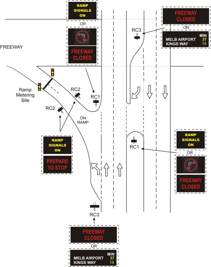
1.2.1.2 A typical layout for RC1 sign at a freeway entrance is shown in Figure 1.1.
1.2.2 Ramp Metering Sign – RC2
1.2.2.1 The RC2 sign is typically placed on an on-ramp to reinforce to drivers that the ramp signals
are operating and to warn drivers of a need to stop.
1.2.2.2 There are two types of RC2 sign as follows:
• RC2-A – Typically installed on an on-ramp providing access to a freeway from an arterial
road.
• RC2- C - Typically installed on freeway to freeway interchange-ramp providing access
from one freeway to an interconnecting freeway.
1.2.2.3 A typical layout for RC2-A sign at a freeway entrance/’on-ramp’ is shown in Figure 1.1.
1.2.2.4 A typical layout for RC2-C sign at a freeway entrance/’on-ramp’ is shown in Figure 1.2.
1.2.3 Ramp Control Sign – RC3
1.2.3.1 RC3 signs are used to provide motorists with information regarding works, incidents or
closures of a freeway
1.2.3.2 RC3 signs are also referred to as Travel Time Sign Type 3 (TT3). See TCS 070 for further
details.
1.2.2.3 There are two types of RC3 sign as follows:
• RC3-A – Typically installed on an arterial road at the commencement of a freeway on-
ramp providing information for the freeway.
• RC3- C - Typically installed before a freeway to freeway interchange ramp providing
information for the interconnecting freeway.
1.2.3.4 The RC3-A sign is generally used to provide travel times along a freeway, operating as a TT3
sign (see TCS 070).
1.2.3.5 The RC3-A sign is also used to provide information to drivers that there is an incident on the
freeway or the freeway is closed.
1.2.3.6 The RC3-C sign is used typically to advise motorists that the ramp signals on the freeway-to-
freeway interchange ramp are operating.
Ramp Control/Metering Signs Page 9 of 72TCS 003 - 2019 Rev. A
1.2.3.7 The RC3-C sign has been designed to be capable of displaying travel times for destinations
along the intersecting freeway(s) as detailed in TCS 070 (operating as aTT5 sign).
Note: at the time of this specification the display of travel times on the RC3-C sign has not
been approved by VicRoads.
1.2.3.8 A typical layout for RC3-C signs at a freeway interchange ramp’ is shown in Figure 1.2.
1.2.4 Ramp Control Sign Designations
1.2.4.1 An overview of ramp control/metering signs and their designations are detailed in Table 1.1
below.
Table 1.1 – Ramp Control/Metering Sign Designations
Ramp Road Use* Approach Display Pixels Pixels Pixel Approximate
Control Designation speed Type (W) (H) Pitch Dimensions
Sign (maximum) (mm)
RC1 Arterial RCRev. A TCS 003 - 2019
Figure1.1 – Typical Layout for RC1, RC2 and RC3 Signs
Arterial Road to Freeway
Ramp Control/Metering Signs Page 11 of 72TCS 003 - 2019 Rev. A
M34 - CITY
RAMP
RC3-C SIGNALS ON
RAMP SIGNALS ON
PREPARE
TO STOP
RC2-C
RC2-C
RC3-C
M12 Fwy
RC3-C
RC2-C
RC2-C
M34 Fwy
RC3-C
M12 – Geelong
Incident on Ramp
Figure 1.2 – Typical Layout for RC2-C and RC3-C Signs
Freeway to Freeway
Page 12 of 72 Ramp Control/Metering SignsRev. A TCS 003 - 2019
1.3 INTELLECTUAL PROPERTY
1.3.1 In relation to all Intellectual Property rights associated with operating the signs, the contractor
grants to VicRoads non-exclusive licence to “use, modify and sell or use that licence for other
purposes that, without the license, could be a breach of the licensors Intellectual Property.
1.3.2 Intellectual Property shall include, but not be limited to, the following:
• Software.
• Source code(s).
• Schematic diagrams.
• Circuit diagrams.
• Wiring diagrams.
• Listings of components and sub-components.
• Any and all operational and maintenance documentation.
1.4 ACRONYMS
The acronyms used in this document shall be interpreted as follows:
ACMA Australian Communications and Media Authority
AS Australian Standard
CCTV Closed Circuit Television
CLI Command Line Interface
CSV Comma Separated Values
DHCP Dynamic Host Configuration Protocol
DNS Domain Name System
EMC Electromagnetic Compatibility
FP Field Processor as used with STREAMS
HTTP Hypertext Transfer Protocol
HTTPS Hypertext Transfer Protocol Secure
ICMP Internet Control Message Protocol
IEC International Electrotechnical Commission
IEEE Institute of Electrical and Electronics Engineers
IP Internet Protocol
ITS Intelligent Transport Systems
LED Light Emitting Diode
PE Cell Photo Electric Cell
RC1 Ramp Control / Metering Sign
RC2 Ramp Metering Sign
RC3 Real Time Information Sign
RCD Residual Current Device
RMS Roads and Maritime Services of NSW (previously known as Roads and
Traffic Authority, RTA)
SSH Secure Shell
SSL Secure Sockets Layer
STREAMS STREAMS is an integrated control system which operates ITS Freeway
Management Devices and other traffic management devices.
TCP/IP Transmission Control Protocol/Internet Protocol
TLS Transport Layer Security
VMS Variable Message Sign
Ramp Control/Metering Signs Page 13 of 72TCS 003 - 2019 Rev. A
SECTION 2 – RELATED SPECIFICATIONS AND
DRAWINGS
2.1 AUSTRALIAN STANDARDS
2.1.1 The fabrication and supply of all components shall conform to the latest version of all relevant
Australian Standards.
2.1.2 The following related Australian Standards are referenced:
AS 1742.2 Manual of uniform traffic control devices, Part 2: Traffic control
devices for general use
AS 1743- Road signs – Specifications
AS/NZ 3000 Wiring Rules
AS 4100 Steel structures
AS 4852.1 Variable message signs – Part 1: Fixed signs
AS 60038 Standard voltages
AS 60529 Degrees of protection provided by enclosures (IP code)
AS/NZS 61000.6.1 Part 6.1: Generic Standards – Immunity for residential,
commercial and light-industrial environments
AS 61000.6.3 Generic standards – Emission standard for residential, commercial and
light industrial environments
AS 61558 Safety of power transformers, power supply units and similar
2.2 VICROADS SPECIFICATIONS AND DRAWINGS
2.2.1 The fabrication and supply of all components shall conform to the relevant VicRoads
specifications, and related specifications and standards, as indicated throughout this
document.
2.2.2 The following VicRoads Specifications are referenced:
Contract Standard Traffic signal installation
Section 730
Contract Standard ITS devices installation
Section 732
Contract Standard Installation of conduits and pits for underground
Section 733
Contract Standard ITS device testing and integration
Section 736
TCS 070 Travel Time Signs
TCG 016 Product Compliance Process for ITS and Electrical Products
Page 14 of 72 Ramp Control/Metering SignsRev. A TCS 003 - 2019
2.2.3 The following VicRoads Standard Drawings are referenced:
TC-2223 RC3 Pole – Typical Arrangement
TC-2224 RC3 Pole Bracketing Arrangements – Typical Arrangement
2.3 ADDITIONAL SPECIFICATIONS AND DOCUMENTS
2.3.1 The fabrication and supply of all components shall conform to the following specifications
and drawings as indicated throughout this document.
2.3.2 The following specifications are referenced:
RMS Specification Colour Sign Interface
ITSM-TO-ITS-CSI-002 Only available from RMS
RMS Specification Communications protocol for roadside devices
TSI-SP-003 Only available from RMS
STREAMS VicRoads ITS platform.
Ramp Metering Managed Freeways: Freeway Ramp Signals Handbook
Handbook
Ramp Control/Metering Signs Page 15 of 72TCS 003 - 2019 Rev. A
SECTION 3 - RC1 RAMP CONTROL / METERING SIGN
3.1 GENERAL
The RC1 signs display advisory and regulatory messages and are provided on the approaches to the
arterial road/entry ramp intersection to face traffic turning onto the ramp.
3.2 DISPLAY REQUIRMENTS
3.2.1 The required displays for use in RC1 signs are shown in Table 3.1
Table 3.1 – RC1 displays
Message
Sign Operation Message Detail
Type
Ramp Metering Yellow text on Black
Operation background
Static RAMP SIGNALS ON
(when ramp signals are
operational)
Ramp Control Red text on Black
Operation FREEWAY CLOSED background
(when freeway is closed)
Alternating Illuminated symbolic type
NO RIGHT TURN
with (based on R2-6)
Illuminated symbolic type
or NO LEFT TURN
(based on R2-6)
Illuminated symbolic type
or NO ENTRY
(based on R2-4)
3.2.2 The symbolic “No Right Turn” and “No Left Turn” displays shall comply with the
requirements of Rule 91 of Road Rules Victoria and AS-1743-2018, for an R2-6A size sign
with an outer radius of 220mm.
3.2.3 Typical pixel placement for the individual displays shall be in accordance with typical layouts
as indicated in Figure 3.1.
Page 16 of 72 Ramp Control/Metering SignsRev. A TCS 003 - 2019
RAMP SIGNALS ON
- Yellow Black
- 120mm character
height
Ramp Metering Operation
FREEWAY CLOSED
- Red on Black
- 150mm character
height
NO RIGHT TURN
- AS 1743, R4-6(R)
- Road Rules Victoria,
Rule 91
NO LEFT TURN
- AS 1743, R4-6(L)
- Road Rules Victoria,
Rule 91
NO ENTRY
- AS 1743, R4-2
- White on Black
characters and
horizontal line
- Nominal 75mm
character height
- Red annulus
Ramp Control Operation
Figure 3.1 – Typical displays for RC1 signs
(provided as examples only)
Ramp Control/Metering Signs Page 17 of 72TCS 003 - 2019 Rev. A
3.2.4 Each message detailed in 3.2.1 shall be referred to as a frame.
3.2.5 Each frame shall be allocated a frame ‘ID’.
3.2.6 Each message shall be allocated to the frame ‘ID’ as detailed in Table 3.2.
Table3.2 – RC1 fixed message frames summary
‘Frame ID’
Message Description
number
1 “Ramp Signals On”
3 “Freeway Closed”
4 Symbolic ‘No Left Turn’
5 Symbolic ‘No Right Turn’
6 Symbolic ‘No Entry’
7 Other Specified Message
3.2.7 The nominal enclosure size shall be 900mm wide by 600mm.
3.2.8 The LED’s shall be arranged in the form of the words and symbols to be displayed.
3.2.9 The sign shall display the frames on a black background.
3.2.10 The LED’s shall have a maximum spacing of 2 times the diameter of the pixel.
Page 18 of 72 Ramp Control/Metering SignsRev. A TCS 003 - 2019
SECTION 4 - RC2 RAMP METERING SIGNS
4.1 GENERAL
4.1.1 The RC2 signs are a warning sign used to indicate that ramp signals are operating and to warn
drivers of the need to stop.
4.1.2 RC2 signs are located on an entry ramp to a freeway.
4.1.3 There are two sizes of RC2 sign currently used by VicRoads, these are:
1. RC2 A Size – This is the standard version of the sign used to provide information to
drivers turning from an arterial road onto a freeway.
2. RC2 B Size – Reserved for possible future use.
3. RC2 C Size – This is a larger version of the sign used to provide information to drivers
turning from one freeway onto another freeway at freeway to freeway interchanges.
4.2 RC2-A DISPLAY REQUIRMENTS
4.2.1 The RC2-A is a changeable message sign.
4.2.2 The RC2-A sign display two alternating messages or frames.
4.2.3 The displays for use in RC2-A sign are shown in Table 4.1.
Table 4.1 – RC2-A displays
Message Detail
“RAMP SIGNALS ON” Yellow on Black
“PREPARE TO STOP” Red on Black
4.2.4 Each message detailed in 4.1 shall be referred to as a frame.
4.2.5 Each frame shall be allocated a frame ‘ID’
4.2.6 Each message shall be allocated to the frame ‘ID’ as detailed in Table 4.2.
Ramp Control/Metering Signs Page 19 of 72TCS 003 - 2019 Rev. A
Table 4.2 – RC2-A fixed message frames summary
‘Frame ID’ number Message Description
1 “Ramp Signals On”
2 “Prepare To Stop”
4.2.7 Typical pixel placement for the individual displays shall be in accordance with typical layouts as
indicated in Figure 4.1.
4.2.8 The LED’s shall be arranged in the form of the words and symbols to be displayed.
4.2.9 The sign shall display the frames on a black background.
4.2.10 The LED’s shall have a maximum spacing 2 times the diameter of the pixel.
4.2.11 The nominal enclosure size shall be 900mm wide by 600mm high.
RAMP SIGNALS ON
- Yellow on Black
- 120 mm character height
“PREPARE TO STOP”
- Red on Black
- 120mm character height
Figure 4.1 – Typical displays for RC2-A signs
Page 20 of 72 Ramp Control/Metering SignsRev. A TCS 003 - 2019
4.3 RC2–C DISPLAY REQUIREMENTS
4.3.1 The RC2-C sign is physically an RC3-A sign being used to display RC2 messages on a freeway
to freeway interchange ramp. Whether a sign is used as a RC2-C Sign or a RC3-A sign is
determined by the sign configuration refer to Clause 1.2.4.
4.3.2 The messages and frame ID’s for the RC2-C sign are the same as for the RC2-A sign in a larger
font height. See Clause 4.1.
4.3.3 Typical displays shall be as shown in Figure 4.2.
RAMP SIGNALS ON
RAMP - Yellow on Black
SIGNALS ON - 180mm character height
PREPARE PREPARE TO STOP
- Red on Black
TO STOP - 180mm character height
Figure 4.2 – Typical layout for RC2-C sign
Ramp Control/Metering Signs Page 21 of 72TCS 003 - 2019 Rev. A
SECTION 5 - RC3 RAMP CONTROL / FREEWAY
CONDITION SIGNS
5.1 GENERAL
5.1.1 RC3 signs are used to provide freeway condition information (including travel times) and
ramp control to drivers.
5.1.2 The RC3 sign is a four colour, full matrix sign, capable of displaying text messages.
5.1.3 The four colours used are red, yellow, green and white.
5.1.4 The four colours shall be generated using individual red, yellow, green and white LED’s.
NOTE: At the time of this specification, the use of a RGB display is not permitted. This is
currently under review.
5.1.5 There are two sizes of RC3 sign currently used by VicRoads, these are:
1. RC3 A Size – This is the standard version of the sign used to provide information to
drivers turning from an arterial road onto a freeway.
2. RC3 B Size – Reserved for possible future use.
3. RC3 C Size – This is a larger version of the sign used to provide information to drivers
turning from one freeway onto another freeway at freeway to freeway interchanges.
5.2 RC3-A DISPLAY REQUIRMENTS
5.2.1 RC3-A signs are typically located on an arterial road prior to an entrance to a freeway.
5.2.2 The RC3-A sign is generally operated as a TT3 sign to display travel times along the
associated freeway. See TCS 070 for details.
5.2.3 The RC3-A sign is also capable of being used to provide real time condition information for
the associated freeway.
5.2.4 RC3-A signs shall be capable of displaying three lines of text.
5.2.5 The display shall have a resolution of 128 pixels wide by 40 pixels high.
5.2.6 The pixels shall typically be square with a maximum pixel pitch (centre to centre spacing) of
12mm in the horizontal and vertical directions.
5.2.7 The pixel width shall not be less than 60% of the pixel pitch.
Page 22 of 72 Ramp Control/Metering SignsRev. A TCS 003 - 2019
5.2.8 Nominal font height shall be:
• 120mm for the top line; and
• 108mm for the second and third lines.
5.2.9 The nominal enclosure size shall be 1660mm wide by 600mm high.
5.2.10 Typical messages for an RC3-A sign are shown in Figure 5.1.
M2 – Light Min Travel Time Information
(most common function, refer
Destination One 9 to Specification TCS 070 for
details)
Destination Two 15
M2 - Incident
at Destination One Incident Information
Long Delays
M2 - Roadwork
from Destination one Roadwork Information
to Destination two
Freeway Closed Freeway Closed used in
Access M2 at conjunction with other ramp
control signs.
Destination Rd
Figure 5.1 – Typical messages for RC3 signs
Ramp Control/Metering Signs Page 23 of 72TCS 003 - 2019 Rev. A
5.3 RC3-B DISPLAY REQUIRMENTS
This clause has been included for possible future use.
5.4 RC3-C DISPLAY REQUIRMENTS
5.4.1 This sign is intended for installation on a freeway prior to an interchange with another
freeway.
5.4.2 This sign is generally used to advise motorists that freeway to freeway ramp signals are
operating.
5.4.3 During adverse conditions, the RC3-C sign is also capable of being used to provide real time
condition information for the associated freeway.
5.4.4 Typical RC3-C sign messages are shown in Figure 5.2.
5.4.5 The RC3-C sign may be used in the future as a TT5 sign to display travel times along the
associated freeway. See TCS 070 for details.
5.4.6 The sign shall be capable of displaying 18 characters per line.
5.4.7 Font height shall be a minimum of 320mm high for all lines.
5.4.8 The display shall have a minimum resolution of 128 pixels wide by 56 pixels high.
5.4.9 The pixels shall typically be square with a maximum pixel pitch (centre to centre spacing) of
32mm in the horizontal and vertical directions.
5.4.10 The pixel width shall not be less than 60% of the pixel pitch.
5.4.11 A border surrounding the active display, of not less than 175mm in width, shall be provided.
5.4.12 The nominal enclosure size should be approximately 4450mm wide by 2150mm high.
5.4.13 The nominal character height to width ratio for all sign types shall be 10:5.
Page 24 of 72 Ramp Control/Metering SignsRev. A TCS 003 - 2019
M2 - City
Ramp Signals On
Ramp Signals On
M2 - City
Ramp Queue
Long Queue
M2 - City
Ramp Closure
Ramp Closed
M2 - City
Ramp Incident
Incident on Ramp
M2 - City
Roadwork Information
Roadwork on
Ramp
Figure 5.2 – Typical message layout for Freeway RC3-C signs
Ramp Control/Metering Signs Page 25 of 72TCS 003 - 2019 Rev. A
SECTION 6 - OPERATION AND CONTROL
6.1 GENERAL
6.1.1 The signs are typically connected via a hardwired link or a wireless link. Different signs that
form part of the same installation may be connected using a combination of link types.
6.1.2 The connection required shall be specified in individual contract documents.
6.1.3 Figures 6.1, 6.2 and 6.3 show the typical communication connections between RC signs and
the Freeway Ramp Signal Roads Side Cabinet.
VicRoads
RC1 STREAMS
Field Processor
RC2
Ramp Metering
Controller
RC3 (TT3 used in
ramp control)
Figure 6.1 – Typical Hard Wired Communications Connections Option 1- Sign Controller
resides within the sign housing
VicRoads
RC1 STREAMS
RC1 Controller
RC2 Controller
RC2
RC3 Controller
Field Processor
Ramp Metering
RC3 (TT3 used in Controller
ramp control)
Figure 6.2 – Typical Hard Wired Communications Connections Option 2 – Sign Controller
resides within road side cabinet
Page 26 of 72 Ramp Control/Metering SignsRev. A TCS 003 - 2019
VicRoads
RC1 STREAMS
Radio
RC2 Field Processor
Ramp Metering
Controller
RC3 (TT3 used in
ramp control)
Figure 6.3 – Typical Wireless Communications Connections - Sign Controller resides within the
sign housing
6.2 SIGN CONTROL PERFORMANCE AND CAPABILITY
6.2.1 The RC3 sign is used for travel time information displays and the message will be updated
every two minutes. Therefore, the RC3 sign shall have the capability to support writing at
least 900 messages a day.
6.2.2 The VicRoads control system uses frames numbers from 200 to 255 for displaying those
frequently updated messages.
6.2.3 Memory containing ‘Message ID’ and ‘frame ID’ designations for fixed messages or frames
shall be retained indefinitely in the absence of power.
6.2.4 The RC sign controller shall retain all configuration data in the absence of mains power. i.e.
all RMS protocol related parameters including message sequences; network and serial
connection parameters.
6.2.5 The response time must be less than 2 seconds.
Note: ‘Response time’ refers to the latency from when VicRoads Field Processor sends
a request message to when a valid response message is received by the Field Processor,
i.e. response time includes the time for transferring the request message from the Field
Processor to the Sign Controller via the serial link, Sign Controller process time for
generating a valid response message and the time for transferring the valid response
from the Sign Controller to the Field Processor via the serial link
6.2.6 The performance requirement in 6.2.4 applies to both wired and wireless serial connections.
Ramp Control/Metering Signs Page 27 of 72TCS 003 - 2019 Rev. A
6.3 SIGN CONTROLLER (SC)
6.3.1 The RC signs shall be controlled by a single Sign Controller. Under normal operation, its
main purpose is to provide both serial and Ethernet interfaces to a third-party controlling
device, over which RMS protocol shall be transmitted in order to control the RC signs.
6.3.2 The sign controller shall be designed to be installed within the RC sign housing or the Freeway
Ramp Signals roads side cabinet depending on the communication connections in section 6.1.
6.3.3 An alternative cabinet may be considered provided it is designed to be mounted onto the
standard VicRoads cabinet foundation.
6.3.4 If the sign controller is to be installed within the Freeway Ramp Signals roads side cabinet,
the sign controller shall be designed to be installed within a standard 19’’ rack. The rack-
mounting chassis shall be no more than 2 RU in height, and either full or half 19’’ rack width.
Half-width 19’’ modules shall be mountable on both the left and the right sides.
6.3.5 All of the controller’s communication and power interfaces shall be clearly and indelibly
labelled on the controller housing.
6.4 ADMINISTRATION AND CONFIGURATION TOOL
6.4.1 The sign controller shall provide an interactive browser-based user interface using HTTP and
HTTPS to provide monitoring, configuration and diagnostic related functions.
6.4.2 Providing a Command Line Interface (CLI) based configuration interface is not mandated,
however, if provided, the interface shall:
a) Support key-based and password authentication, with the capability to disable password
authentication
b) SSH v2.x shall be required (SSH v1 shall not be used)
c) Only support CLI over TCP/IP. The SC shall not have any serial-based console port on
the controller chassis, which can be used to access the SC CLI interface.
6.4.3 The software shall provide for the display and monitoring of the sign controller configuration,
including:
a) Site Name
b) Firmware version
c) Current Temperature of the controller
d) Main Power Supply status
e) Backup Power Supply Status (if one exists)
f) Up Time (since last reset)
g) System time (Local date and time)
h) MAC Address(es) of all Ethernet port(s)
i) Current Active Control Mode (Local, serial, TCP or any other mode if present)
j) Facility Switch position
k) All the signs connected to the controller and, for each sign, the following information
shall be displayed:
i. Sign Type (RC1, RC2-A, RC2-C, RC3-A or RC3-C)
ii. RMS protocol Group ID
Page 28 of 72 Ramp Control/Metering SignsRev. A TCS 003 - 2019
iii. RMS protocol Sign ID
iv. Dimensions (in pixel)
v. Luminance dimming control mode (Auto, Time based or Fixed)
vi. Current Luminance dimming level
vii. RMS Protocol Session Status (Online / Offline)
viii. RMS Protocol Display Mode(Message, Frame or Plan)
ix. RMS Protocol Display Message Number/Frame Number/Plan Number
x. Current Sign firmware version
6.4.4 Configuration Functions – The software shall allow a user to change sign controller and sign
configurations using the browser interface. In general, all configuration changes shall be
applied immediately and take effect without the need to restart/reset the sign controller.
However, changing certain parameters may cause any currently active connection to be
dropped, for example, the sign’s password or seed offset, IP port number, etc. The following
parameters shall be configurable.
(a) The Site Name – Text field with minimum 150 characters.
(b) Control Mode – The software shall allow a user to choose an active control mode from
the following:
i. Local mode – When this mode is enabled, a user can use the browser interface
to control the sign display to display a message or run test patterns. When this
mode is disabled, a user shall not be able to use this web software to control
the sign display to display a message or run test patterns.
ii. Serial – When this mode is enabled, the master (refer to RMS protocol section
2.1) software can connect to sign controller via serial connection, and control
the sign using RMS protocol. When this mode is disabled, and there is
currently an active serial connection, the controller shall drop the connection
and blank the sign(s).
When this mode is disabled and the master software attempts to connect to the
sign controller via the serial connection using RMS protocol, the sign
controller shall respond with a ‘Reject’ message (MI code 00h) with
Application Error code ‘01’ (Device Controller offline) to the ‘Start Session’
message (MI code 02h) sent by the master software. However, the sign
controller shall still respond to ‘Heartbeat Poll’ messages (MI Code 05h) as
specified in RMS Protocol Section 3.6.3.6.
(c) TCP/IP – When this mode is enabled, the master (refer to RMS protocol section 2.1)
software can connect to sign controller via TCP/IP connection, and control the sign
using RMS protocol.
When this mode is disabled, if there is currently an active TCP/IP connection, the
controller shall drop the connection and blank the sign(s). When this mode is
disabled and the master software attempts to connect to the sign controller via TCP/IP
using RMS protocol, the sign controller shall respond with a ‘Reject’ message (MI
code 00h) with Application Error code ‘01’ (Device Controller offline) to the ‘Start
Session’ message (MI code 02h) sent by the master software. However, the sign
controller shall still respond to ‘Heartbeat Poll’ messages (MI Code 05h) as specified
in RMS Protocol Section 3.6.3.6.
Note: the control mode is exclusive. Once a mode is chosen, the other two modes shall
be disabled.
Ramp Control/Metering Signs Page 29 of 72TCS 003 - 2019 Rev. A
(d) (For RC2-C/RC3-A only) Sign Type – either ‘RC2-C’ or ‘RC3-A’
When the sign is configured as ‘RC2-C’ sign, the sign shall be able to only display
predefined messages/frames as specified in Section 4.3.
When the sign is configured as ‘RC3-A’ sign, the sign shall be able to display all
dynamic messages generated and requested by the VicRoads Control Systems. And
the predefined messages/frames for ‘RC2-C’ shall be also available in this mode.
6.4.5 Network configuration – The software shall allow a user to change the following network
configurations:
a) IP address allocation (DHCP or static).
b) If the IP address allocation is static – the following parameters: IP Address, Subnet Mask,
Default Gateway, Primary DNS and Secondary DNS.
6.4.6 RMS Protocol Configuration – The software shall allow a user to change the following RMS
Protocol and communications related configuration parameters:
a) IP Port used for TCP/IP connection.
b) Session time out for TCP/IP connection (in seconds).
c) Security settings for TCP/IP connection (such as switch between no encryption and TLS
encrypted, TLS port to be used).
d) Baud rate, Data bits, Parity and Stop bits for serial connection.
e) Session time out for serial connection (in seconds).
f) Seed offset (in Hex).
g) Password offset (in Hex).
h) Polling Address.
i) Broadcast Address.
j) Blanking Time out (in minutes, the duration that the sign controller will wait before
blanking the sign after the active RMS protocol connection is disconnected.).
k) Sign ID and Group ID (For individual signs).
6.4.7 Luminance Dimming control – The software shall allow a user to change the following sign
dimming control related configuration for each individual sign connected to the sign
controller:
a) Luminance Dimming control mode (Auto, Time Based or Fixed). Three modes are
defined in AS 4852.1 – 2009 Section 3.11.
b) The controller shall have pre-defined Melbourne ‘Dawn’ and ‘Dusk’ times for Time
Based mode as specified in AS 4852.1 – 2009 Section 3.11 and the software shall allow
a user to change those time settings.
c) Fixed Dimming Level (in ‘Fixed’ mode only).
6.4.8 System Time – The software shall allow a user to change the current time, time zone, Daylight
saving option and whether to use an NTP server for time synchronisation. The IP address(es)
of the NTP servers shall be configurable.
6.4.9 Security – The software shall:
a) Allow a user to change the browser interface’s username and password.
b) Support both HTTP and HTTPS and allow a user to choose the access mode from ‘HTTP
only’, ‘HTTPS only’ and ‘Both HTTP and HTTPS’.
Page 30 of 72 Ramp Control/Metering SignsRev. A TCS 003 - 2019
c) Allow a user to change the TCP/IP ports used for ‘HTTP’ and ‘HTTPS’.
d) Allow a user to change the session timeout for the browser interface (duration after the
last active web request received).
6.4.10 Control and Testing – The software shall allow a user to perform local control and display test
patterns functions specified in Section 6.13 “Local Control” and 6.18 “Display Test Patterns”
of this specification.
6.4.11 Administration – The software shall provide the following administration functions.
6.4.12 Firmware upgrade
a) The software shall allow a user to the upgrade the controller’s firmware. After the
firmware is upgraded, all existing pre-configured parameters (IP addresses, network
mask, default gateway and etc) for the controller shall be maintained.
b) The software shall allow a user to upgrade firmware for individual signs that are
connected to the sign controller.
c) The system shall ensure that the entire firmware file is successfully downloaded before
attempting to apply the firmware upgrade.
6.4.13 Save /recover configuration to/from file.
a) All of the configuration parameters for the controller shall be able to be saved and
retained after rebooting the controller.
b) The software shall allow a user to save the current configuration to a local file and be
able to restore all the configuration parameters from the file.
6.4.14 Reboot and Reset.
The software shall allow a user to reboot/reset the controller with the following options:
a) Reset to manufacturer default.
b) Reset to manufacturer default, except for the current network configuration (IP addresses,
network mask, default gateway, etc).
c) Reboot the controller with all configuration maintained.
6.4.15 Reports/logs
The software shall provide separated log files, one for RMS protocol commands and another
for any other system logs. All the logs shall be able to be displayed via the web interface and
to be exported to text or CSV format files.
The software shall allow the user to choose start date/time and end date/time to only display
or export selected period of logs.
6.4.16 System event logs
The software should log the following system events as minimum:
a) Controller and sign fault events.
b) RMS protocol connection events (only require connection and disconnection events).
c) The login / logoff events for the browser interface software, including any failure
attempts. The parameters to be logged include the attempted usernames, passwords and
source IP addresses.
Ramp Control/Metering Signs Page 31 of 72TCS 003 - 2019 Rev. A
The software shall keep a minimum of the last 90 days or 10000 log entries, whichever limit
comes first. Each log shall contain a timestamp with the resolution to 1ms.
6.4.17 RMS messages logs
The software shall log RMS protocol messages between the master software (VicRoads
Control System) and the controller for the last 90 days or 10000 messages, whichever limit
comes first. Each log shall contain:
a) Message direction (from the master to the controller or vice versa).
b) A timestamp with resolution to 1ms (The time the commands received or the response
sent).
c) The actual message detail in a Hex string.
The software shall support two RMS command log options as below. And the software shall
set option 2 as default but allow users to change log options via the user interface.
Option 1 – Full log mode - When this option is chosen, the software shall log every RMS
protocol message
Option 2 – Simple log mode (default option) - VicRoads Control System sends RMS protocol
status and fault checking messages listed in Table 6.1 to the sign controller very frequently
(could be from every 2 to 10 seconds). This option is to reduce logging regular status and fault
checking messages and focus on irregular control messages.
When the is options is chosen, the software shall log every RMS protocol message except for
those listed in Table 6.1.
Table 6.1
Message Name MI Code
Heartbeat Poll 05
Sign Status Reply 06
Sign Extended Status Request 1B
Sign Extended Status Reply 1C
Retrieve Fault Log 18
Fault Log Reply 19
The software shall only log the messages listed in Table 6.1:
d) Once every hour
e) And the next five consecutive messages after any other RMS protocol messages not listed
in Table 6.1 are sent from the VicRoads Control System.
6.4.18 Non-functional requirements
(a) Performance – The software shall respond to every user interaction less than 3 seconds
(excluding delays in the network).
(b) Security -
Page 32 of 72 Ramp Control/Metering SignsRev. A TCS 003 - 2019
i. The software shall verify the username and password before granting access to the
system.
ii. The software shall support both HTTP and HTTPS and allow a user to choose access
mode from ‘HTTP only’, ‘HTTPS only’ and ‘Both HTTP and HTTPS’.
iii. Only TLS shall be used for the HTTPS connection.
iv. The current VicRoads document ‘Information Security Standard: Cryptographic
Controls’ shall be complied with.
v. After three successive failed login attempts, the minimum time allowed between
login attempts shall be changed to 60 seconds.
(c) Bandwidth /network requirement
The software shall be designed to run on a relatively slow IP network, such as 3G wireless
network with around 500Kbps bandwidth and 500ms latency. The user interface shall be
simple to avoid long response times. Where large amounts of information is to be
displayed (such as logs), the information shall be displayed over multiple pages with
page down and page up functions.
(d) All the configuration changes shall immediately take effect once the configuration item is
saved without the need of rebooting or power cycling the sign controller.
6.5 RESET
6.5.1 On reset or reboot of the sign controller and/or sign (regardless of source), the sign display
shall be set to blank.
6.5.2 The sign controller shall incorporate a reset button accessible on the front chassis. The reset
button shall perform a soft reset the SC & Connected sign. All configurations within the SC
and sign shall be maintained.
6.5.3 The sign controller shall not provide any hard reset (reset the controller to manufactory
default) mechanism (such as button), which can be accessed via the chassis.
6.6 SIGN CONTROLLER PARAMETER DEFAULT SETTINGS
The default settings for key parameters within the SC shall be as shown in Table 6.1.
Ramp Control/Metering Signs Page 33 of 72TCS 003 - 2019 Rev. A
Table 6.1 – Sign controller key parameters
Parameter Description Default Setting
Username required for access to the SC’s Web
SC login user name ‘Admin’
based tool
Password required for access to the SC’s Web
SC login password to be provided by VicRoads.
based tool
The SC’s Site name to be displayed in the Web VicRoads allocated Site
SC Site Name
based tool Number (RAI ID)
STATIC
Selectable DHCP or statically configurable IP
SC IP address IP: 192.168.30.1
address and Netmask
Mask: 255.255.255.0
no encryption TCP : 43000
RTA over, TCP/IP TCP port numbers for RTA/RMS protocol
TLS encrypted TCP:43002
connection
Default: no encryption
Default RTA address RTA/RMS Protocol group and sign address All addresses to start from 1
RS422
Serial configuration Hardware serial settings
38400kbps, 8 N 1
TCP port number used for web access to the
HTTP: TCP 80
Web Access Ports Web based tool
HTTPS using TLS: TCP 443
Telnet TCP port number used for connection to the CLI TCP 6368
Control Mode Default controller RTA control mode TCP
Luminance Dimming
Default Luminance Dimming Control Mode Auto
Control Mode
Session time out for TCP/IP connection (in
RTA TCP Time out 300
seconds)
Session time out for serial connection (in
RTA serial Time out 180
seconds)
in minutes, the duration that the controller to
Blanking Time out black the sign after the active RTA/RMS 5
protocol connection is disconnected
in minutes, the duration that the current Web
Web Access Timeout tool connection to be after the last active web 5
request is received.
6.7 ETHERNET
6.7.1 The SC shall provide at least one 10/100 TX Ethernet interface. The Ethernet interface shall
support the modes of communication and protocols detailed in Sections 6.8, 6.9 and 6.10 of
this specification.
Page 34 of 72 Ramp Control/Metering SignsYou can also read