Real-Time Feedback-Controlled Robotic Fish for Behavioral Experiments With Fish Schools
←
→
Page content transcription
If your browser does not render page correctly, please read the page content below
INVITED
   PAPER

Real-Time Feedback-Controlled
Robotic Fish for Behavioral
Experiments With Fish Schools
Use of cyber–physical robotic fish to study fish-school behavior is proposed
in this paper; each robotic fish gets video feedback from the fish group and
its environment.
By Daniel T. Swain, Student Member IEEE , Iain D. Couzin, and
Naomi Ehrich Leonard, Fellow IEEE

ABSTRACT         |   Integrating robotic agents into animal groups                     KEYWORDS    |   Collective decision making; cyber–physical sys-
creates significant opportunities for advancing experimental                           tems (CPSs); feedback control; fish schooling; real-time;
investigations of collective animal behavior. In the case of fish                      robotics; video processing
schooling, new insights into processes such as collective deci-
sion making and leadership have been made in recent expe-
riments in which live fish were interacting with robotic fish
                                                                                       I . INTRODUCTION
driven along preplanned paths. We introduce a new cyber–                               Fish schools exhibit remarkable collective behavior
physical implementation that enables robotic fish to use real-                         that reflects a highly efficient group-level capability to
time feedback to control their motion in response to live fish                         forage, migrate, and evade predators [1]–[6]. As a group,
and other environmental features. Each robotic fish is magne-                          fish are observed both to respond quickly to external envi-
tically connected to, and thus moved by, a wheeled robot                               ronmental signals of significance and to move together
underneath the tank. Real-time image processing of a video                             despite uncertainties and disturbances in the environment
stream from an overhead camera provides measurements of                                [7]. In order to better know and predict these kinds of
both the robotic fish and the live fish moving together in the                         behaviors, it is critical to understand processes associated
tank. Feedback responses computed from these measurements                              with collective decision making and collective motion.
are communicated to the robotic fish using Bluetooth. We show                          This requires investigating the mechanisms that connect
results of demonstrations and discuss possibilities that our im-                       the choices that individual fish make in response to what
plementation affords for new kinds of behavioral experiments                           they can sense with the complex behaviors that emerge at
with fish schools.                                                                     the level of the group. Identification of these mechanisms
                                                                                       can also provide the means to develop principled design
                                                                                       methodologies that enable groups of engineered agents,
                                                                                       e.g., robotic mobile sensor networks, to achieve high
                                                                                       performance in demanding tasks such as environmental
                                                                                       monitoring, search, and exploration [8], [9].
Manuscript received June 30, 2011; accepted August 10, 2011. Date of publication           Fish schools are typically leaderless aggregations of
October 19, 2011; date of current version December 21, 2011. This work was supported   selfish individuals where direct access to stimuli from the
in part by the U.S. Office of Naval Research under Grant N00014-09-1-1074. All
experimental work was carried out in accordance with federal and state regulations,    external environment may be limited to a small number of
and was approved by Princeton University’s Institutional Animal Care and Use           individuals on the periphery. Fish gain access to informa-
Committee.
D. T. Swain and N. Ehrich Leonard are with the Department of Mechanical and            tion through social cues from their neighbors [10], [11].
Aerospace Engineering, Princeton University, Princeton, NJ 08544 USA (e-mail:          For example, an individual fish that does not sense a pre-
dswain@princeton.edu; naomi@princeton.edu).
I. D. Couzin is with the Department of Ecology and Evolutionary Biology, Princeton     dator directly may instead sense its neighbor turning fast
University, Princeton, NJ 08544 USA (e-mail: icouzin@princeton.edu).                   and make adjustments to turn with it, thus staying with the
Digital Object Identifier: 10.1109/JPROC.2011.2165449                                  school and avoiding the predator.

150      Proceedings of the IEEE | Vol. 100, No. 1, January 2012                                                     0018-9219/$26.00 Ó 2011 IEEE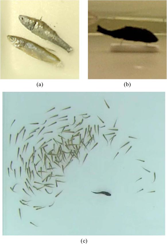
Swain et al.: Real-Time Feedback-Controlled Robotic Fish for Behavioral Experiments With Fish Schools

    Investigating mechanisms that explain fish schooling          feedback control for the robotic fish, our implementation
therefore requires an exploration of information passing          significantly expands opportunities for manipulating the
and decision making at the level of the individuals. Expe-        behavior of the robotic members of a mixed group of robots
riments have been run, for instance, to explore the role of       and fish and as a result expands the scope for new be-
different sensing modalities in fish [12], the role of school     havioral experiments with fish schools.
density on collective response to predation risk [13], and            Measurements available to the robotic fish can include,
the relationships between group speed, group polarity, and        for example, relative position, heading, and/or speed of
mean nearest-neighbor distances [14]. Additional empir-           neighbors; this enables a robotic fish to adopt a responsive
ical studies of fish schools are described in [15]–[17].          behavior modeled after a conspecific. Likewise, real-time
    In recent years, researchers have introduced robots           processing of measurements yields features of the school,
that interact with live animals as a new tool for studying        such as centroid, boundary, polarity, and momentum; this
social behavior in animal groups; for a survey, see [18]. The     enables a robotic fish to adopt a responsive behavior
objective is to infiltrate the live animal group with robotic     modeled after a predator.
animal replicas that are designed to behave as conspecifics           Like the robotic fish in [2], each of our robotic fish
or heterospecifics. By being able to manipulate the be-           consists of a replica fish in the tank that is magnetically
havior of the robotic members of a mixed group of inter-          coupled with an actuator beneath the tank. However,
acting animals and robots, new opportunities are created          instead of being driven by a pulley system, each replica fish
for inferring mechanisms of collective behavior from              is magnetically connected to a wheeled robot that moves
observations.                                                     freely underneath the tank. Feedback measurements are
    In the experiments of [19], robotic cockroaches moved         provided from real-time image processing of a video stream
as conspecifics with live cockroaches in an arena with            from a camera overhead the tank. The video stream cap-
shelters. The robots could sense shelters and shelter dark-       tures the behavior of the robotic fish, the live fish, and
ness and discriminate between live and robotic cock-              anything else in the tank, and it is linked by a FireWire
roaches. Their behavior was programmed according to a             interface to a computer where real-time tracking is per-
parameterized model of shelter seeking; by manipulating           formed. From the tracking data, a range of properties of the
the parameters the robotic cockroaches were seen to in-           mixed robot-fish group are computed in real time and these
fluence the collective decision making of the mixed robot-        are used as feedback in the control algorithm implemented
animal group. The results yielded new insights on the role        on the computer for each of the robotic fish. The resulting
of social interaction in collective decision making in cock-      actuation signals, which command robot wheel speeds, are
roaches and demonstrated the possibility of using robots to       sent to the robotic fish through Bluetooth channels.
control animal behavior.                                              A critical ingredient and contribution of our work is the
    Interactive robots have also been used in behavioral          design and integration of real-time tracking and compu-
experiments with fish schools. In [20], a pair of remotely        tation of features of the fish school. Existing work on
controlled dead fish was used to test cooperation in preda-       offline fish tracking includes [14], [22], and [23]. There
tor inspection. In [1], two remotely controlled robotic fish,     has been very recent work on real-time tracking of humans
moving along guide lines, were used as conspecifics with          using laser range finders [24] and real-time tracking of
live fish to investigate quorum responses in collective           flies in three dimensions using multiple cameras [25]. The
movement decisions. In [2], a computer-controlled robotic         tracking approach of [25] is similar to ours, although in
fish was designed to move around a tank as a conspecific          [25] multiple computers are used to capture motion in
with live fish in order to test hypotheses on mechanisms of       three dimensions, whereas we only require a single com-
recruitment and leadership in fish schools. The body of the       puter for our 2-D setting. Additionally, segmentation is not
robotic fish was a replica mounted on a magnetic base that        a significant issue in [25] since the multiple cameras eli-
was controlled by an electromagnet underneath the tank.           minate most occlusions, whereas we need to implement a
By programming the motors of a pulley system that con-            real-time segmentation algorithm that can resolve signifi-
trolled the electromagnet in two dimensions, the robotic          cant and frequent occlusions. The segmentation algorithm
fish was made to follow a specified route at a specified speed.   we use in real time is similar to the one used offline for
    Aureli et al. [21] have developed a free-swimming fish-       flies in a planar arena in [26].
like robot that is only 13 cm long; while this robot is not           Our approach to tracking and to computing properties
meant to function as a conspecific it has been shown to           of fish schools in real time balances accuracy and com-
actively engage a school of fish in a tank.                       putational efficiency. Segmenting the images of individual
    In this paper, motivated by the works of [1], [2],            fish is a particular challenge because conspecifics look
and [19], we present a new cyber–physical implementation          nearly identical and they swim very close to one another.
of robotic fish with live fish where the robotic fish have        We successfully perform segmentation in real time using an
available real-time feedback measurements of their envi-          expectation–maximization mixture-of-Gaussian (EMMG)
ronment and can control their own motion in response to           algorithm [27], [28]. For data association, we use the
these measurements. By facilitating versatile real-time           Hungarian (Munkres) assignment algorithm [29], [30] to

                                                                  Vol. 100, No. 1, January 2012 | Proceedings of the IEEE   151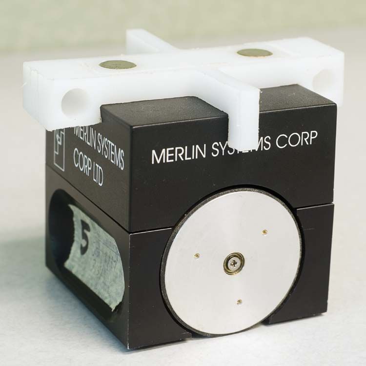
Swain et al.: Real-Time Feedback-Controlled Robotic Fish for Behavioral Experiments With Fish Schools

Fig. 1. Four frames from the overhead video stream of a robotic predator fish with a live school of golden shiners in the testbed with real-time
tracking output overlaid. Frames (a), (b), (c) and (d) are ordered in time with frame (a) the earliest. In each frame, the tracked position and
heading angle of the robotic fish are represented by the thick blue line. The green ellipse(s) represents the approximate boundary of the
live fish school, and the small green circle(s) represents the location of the centroid of the live fish school. In frame (a), two subgroups of
live fish are successfully identified and tracked; the subgroups have joined to make one connected group in frame (b). The robotic predator
approaches and intrudes in frames (c) and (d).

assign an identity to a blob that minimizes distance from                 green ellipse (or ellipses) identifies the computed approx-
the previous tracked location to the centroid of the blob in              imate boundary of the school, and a small green circle
the current image. Particle filter methods have been used                 identifies the computed centroid of the school. The robotic
successfully in offline tracking of multiple objects [22],                predator can be triggered to approach the school as a
[31], [32], but they proved to be insufficient for our real-              function of the time-varying value of these features.
time tracking problem. Instead, we use the unscented                          We describe our mixed robot-fish testbed and its com-
Kalman filter (UKF) [33], [34]. The UKF provides state                    ponents in further detail in Section II. In Section III, we
estimates from which we compute fish school properties.                   present our approach to real-time tracking and computation
    Fig. 1 shows four snapshots from the overhead video of                of fish school features. In Section IV, we describe two
our experimental tank with a school of golden shiners                     example behavioral experiments with fish schools that were
(Notemigonus crysoleucas) and a robotic fish behaving as a                used to demonstrate our real-time feedback-controlled
predator. Superimposed on each snapshot are features                      robotic fish interacting with a live fish school. We conclude
identified in real time; the thick blue line identifies the               in Section V and discuss possible future experiments with our
computed position and orientation of the robotic fish, a                  testbed.

152    Proceedings of the IEEE | Vol. 100, No. 1, January 2012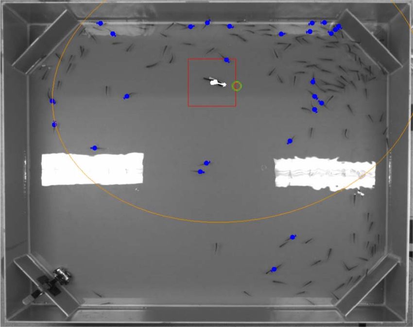
Swain et al.: Real-Time Feedback-Controlled Robotic Fish for Behavioral Experiments With Fish Schools

Fig. 2. Diagram of the mixed robot-fish testbed components.

                                                                allows the tank base to be only 1/4 in thick and still resist
II . T E ST B ED FO R I N TE R A CT I NG LI VE
                                                                significant bowing from the weight of the water. The thin
AND ROBOTIC FISH
                                                                tank base is important because it ensures the strength of
A diagram of the mixed robot-fish testbed is shown in           the magnetic coupling between model fish and wheeled
Fig. 2. Live and robotic fish swim together in a shallow,       robot throughout the tank area.
freshwater tank. Because the live fish move predominantly           Securing bolts are placed along the periphery of the
in the horizontal plane, the robotic fish are designed for      tank, fixing it to the support frame. The sides of the tank are
horizontal motion. Each robotic fish is a model fish in the     1/8 in thick to keep weight low and 12 in high to prevent
tank magnetically connected to, and thus moved by, a            fish from jumping out of the tank. There is a 12-in piece
wheeled robot moving freely on a platform underneath the        placed diagonally across each corner to prevent fish from
tank. Two cameras are mounted overhead: one FireWire            congregating in the corners. One of these corner pieces has
camera acquires real-time video and one high-definition         a small hole drilled through the bottom to allow water into
(HD) camera records video for offline analysis after the        that corner where there is a drain hole. A drain valve and
experiment. Tracking, school features, and feedback             attached pump allow the tank to be drained quickly, if
control laws are computed on a computer workstation;            necessary. A view from overhead the tank is shown in
control inputs are sent from the workstation over Blue-         Fig. 3. In the photo, an underwater camera is clamped to
tooth channels to each wheeled robot.                           the bottom left corner piece; this is an optional feature.
    In this section, we describe the hardware and software          In addition to providing structural support, the base
components of the testbed. The real-time tracking is            supports a platform that is suspended below the tank. This
described in more detail in Section III.                        platform is the surface on which the wheeled robots move
                                                                freely. A long access port is cut into one side of the base so
A. Hardware                                                     that wheeled robots can be inserted and removed. The
    In this section, we describe the hardware associated        vertical standoff distance between the platform and the
with the arena, the wheeled robots, the model fish, and the     bottom of the tank can be adjusted to accommodate vary-
tracking.                                                       ing degrees of bowing, robot height, and magnet strength.
                                                                The nominal vertical distance is 4 in.
   1) The Arena: The arena consists of a 4-ft by 5-ft by
12-in-high watertight tank mounted on a wooden base. For           2) Wheeled Robots: Merlin Systems Corp. MiaBot Pro
the experiments, the water in the tank is typically 2.5–3 in    wheeled robots [35] are used to move the model fish.
high. The tank is constructed using Garolite G10 fiberglass     These wheeled robots were selected because they can be
composite. This material provides superior stiffness and        controlled wirelessly with Bluetooth, and they have a high

                                                               Vol. 100, No. 1, January 2012 | Proceedings of the IEEE    153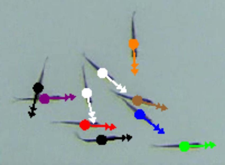
Swain et al.: Real-Time Feedback-Controlled Robotic Fish for Behavioral Experiments With Fish Schools

Fig. 3. A frame from the overhead video stream of a robotic predator
fish chasing the centroid of a live school of golden shiners with         Fig. 4. MiaBot Pro wheeled robot with hood and a pair of cylindrical
real-time tracking output overlaid. The robotic predator’s measured       rare-earth magnets press-fit into holes in the hood insert.
and tracked position and heading are each represented by a white dot
and arrow and the restricted area for segmenting the robotic predator
is outlined in red. The position and heading of each individual
segmented live fish are represented by a blue dot and small blue          insert. A pair of cylindrical rare-earth magnets, 1/2-in
arrow. The threshold  for segmenting fish is set high, and therefore a   diameter and 1/4-in thick, are separated by 2 in so that they
relatively small number of individual fish are segmented. The orange
ellipse represents the moment-based estimate of the school boundary,
                                                                          are centered on the robot and aligned front to back with
and the green circle represents the position of the school centroid.      the direction of motion. Alternate magnet sizes and
Reflections are present from overhead lights in the laboratory during     configurations can be accommodated by manufacturing a
this demonstration.                                                       new insert. The height of the magnets can also be adjusted
                                                                          by inserting shims behind the rectangular insert. The two
                                                                          circular faces of each magnet correspond to its poles; they
                                                                          are inserted into the hood with opposite poles facing up.
speed and turning rateVup to 3 m/s and 85 rad/s, re-                      The opposite pole orientation facilitates torque transfer to
spectively. Each robot consists of two wheels mounted on                  the model fish when the robot turns and ensures that the
either side of a 7.5-cm cube containing a motor for each                  correct mating orientation is maintained. The wheeled
wheel, batteries, and electronics; see Fig. 4. The wheels                 robot can sometimes lose traction as it pulls the model
are both parallel to the sides of the robot and their spin axis           fish; however, weights can be added to the hood in order to
runs right through the middle of the cube. The speed of                   increase the robot’s traction.
each wheel can be controlled independently forward and
backward so that the robot can be made to translate (for-                     3) Model Fish: The model fish appearance can be a
ward and backward) and to turn using speed differentials.                 critical factor in the success of an experiment, particularly
For each motor there is an encoder, which is used onboard                 if the robotic fish is to be treated as a conspecific by live
in a feedback loop that controls the wheel speed to a                     fish. Different species respond differently to models. For
desired speed input to the robot. Plastic nubs prevent the                example, in [1] and [2], it was observed that three-spined
robots from rocking forward or backward on their axles.                   sticklebacks (Gasterosteus aculeatus L.) responded well to
    The wheeled robots are well suited to emulating the                   robotic conspecifics when realistic eyes were painted on
translation and turning movements of fish, although they                  the models. Golden shiners have proved to be more
cannot simulate body contortions and side drifting. Their                 difficult in this regard. One of the golden shiner models in
high speed and turning rate make it possible to model                     a series under development is shown in Fig. 5(a). This
many rapid fish behaviors, including those of a predator                  golden shiner model was created from a mold of a deceased
darting to pursue its prey. Achievable accelerations are                  golden shiner [also shown in Fig. 5(a)] using a hard plastic;
also high with practical limits resulting from motor slip,                the plastic allowed realistic painting but prevented good
latency in the closed-loop control, and drag forces acting                reproduction of structural features.
on the model fish.                                                            The live golden shiners responded, in the demonstra-
    A machined plastic hood is mounted snugly to the top                  tions described below, to a model koi used to simulate a
of each robot as shown in Fig. 4. Each hood has a milled                  predator fish. Fig. 5(b) shows an underwater view of the
rectangular slot with a rectangular plastic insert. Magnets               koi model mounted on its base. The model was created by
are press-fit into holes that are drilled into the rectangular            casting from a mold of a deceased koi. The molding and

154    Proceedings of the IEEE | Vol. 100, No. 1, January 2012
Swain et al.: Real-Time Feedback-Controlled Robotic Fish for Behavioral Experiments With Fish Schools
The camera is mounted so that the image plane is close
to parallel with the plane of the tank bottom. As a result,
feedback control of the robotic fish from its tracked
position provides satisfactory performance without requir-
ing scaling from robot wheel speeds to speed in image
coordinates. Correction for refraction due to Snell’s law
can be neglected due to the shallow depth of water com-
pared to the distance between the camera and the water.
Future experiments requiring high precision may neces-
sitate calibration of the camera system to obtain real-world
coordinates. Calibration of the HD camera is also neces-
sary for offline analysis so that experimental results can be
reported accurately in real-world units.
B. Software
In this section, we give an overview of design of the
tracking and control software package that we have
developed.
1) The MADTraC Library: The Multi-Agent Dynamic
Tracking and Control (MADTraC) library [38] was devel-
oped in the Dynamical Control Systems Laboratory
(DCSL) at Princeton University, Princeton, NJ, to support
several applications for which a high-performance tracking
and control framework was needed. MADTraC provides a
cross-platform C++ GUI framework and a collection of
helper classes that enable rapid application development.
The framework is quite flexible, focusing on applications
that perform (real-time) tracking on acquired video,
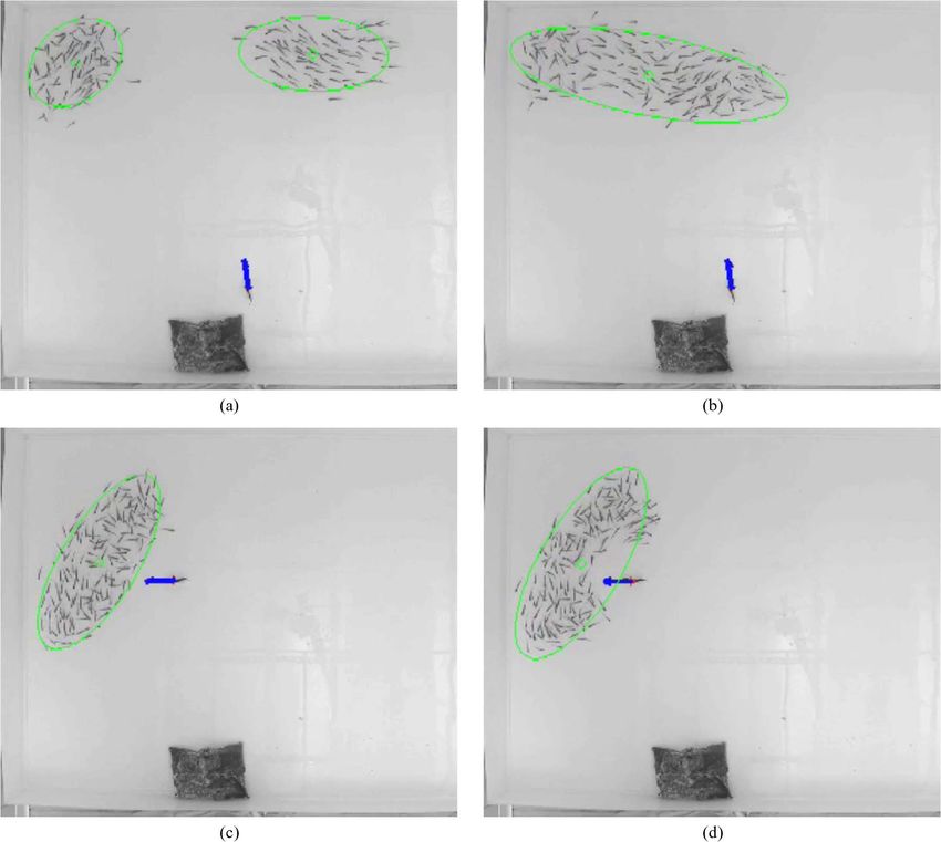
Fig. 5. (a) Deceased golden shiner (bottom) and a model golden shiner
provide live visualization and parameter adjustment
(top) produced from a mold of the deceased shiner using a hard plastic. capabilities, and send control commands to an external
(b) Silicone koi predator model mounted on its magnetic base. The device. The video source can be a video file, or one or
photo is taken from an underwater camera in the tank. (c) Overhead multiple USB or FireWire cameras. Almost any tracking
snapshot of robotic koi predator with live golden shiner school
algorithm can be used through inheritance of the base
in the tank.
tracking class. Many of the techniques described in this
paper are provided as modules that can be plugged in to
customize the tracking algorithm. Other features of the
model material are both tin-cured silicone rubber library include parameter persistence (i.e., the values of
(MoldMax 30T and 15T, respectively) distributed by parameters are saved between successive runs of the
Smooth-On, Inc. [36]. The silicone rubber mold and program), data output formatting, and the ability to save
model create flexible, high-quality replicas of the fish screen shots and movies directly from within the
shape and texture. Painting silicone rubber requires spe- application.
cialty paints, and it is difficult to reproduce the markings
on a fish. The model koi is painted black as seen in the 2) Communication and Control: Communication between
overhead snapshot of Fig. 5(c) of the model moving with a the workstation and the MiaBot Pro wheeled robot is
live golden shiner school. established with a virtual serial port over a Bluetooth
channel. Multiple robots are easily handled by opening a
4) Tracking System Hardware: An Allied Vision Tech- separate port for each robot, up to seven robots. The
nologies Guppy F-080 grayscale FireWire camera [37] with number seven is a limitation of the Bluetooth standard and
1032 778 resolution and a 4.5-mm lens is mounted 3 m can be overcome with specialty hardware. Wheel speed
above the tank. The camera is connected to a computer commands are sent to the robots at each time step using
workstation for tracking, computation, and control. The an ASCII string protocol. The robots have onboard
workstation uses modern commodity hardware for real- proportional–integral–derivative (PID) feedback control
time tracking, a FireWire port for the camera, and either of wheel speeds using motor encoder feedback. This
built-in Bluetooth or an off-the-shelf USB Bluetooth inner loop control is sufficiently fast so that robots can
adapter for communication with the robotic fish. be commanded with desired wheel speeds.
Vol. 100, No. 1, January 2012 | Proceedings of the IEEE 155Swain et al.: Real-Time Feedback-Controlled Robotic Fish for Behavioral Experiments With Fish Schools
Feedback laws that model conspecific or heterospecific The above simple control law is sufficient when there
behaviors are applied to produce desired steering and are few constraints. More sophisticated motion planning
speed control for the robotic fish. For example, a feedback and feedback solutions for control of nonholonomic vehi-
law for a conspecific robotic fish will typically require an cles can easily be substituted.
update on steering in response to measurements of relative
position, heading, or speed of near-neighbor fish. A feed-
back law for a predator robotic fish will typically require an I II . REAL-TIME TRACKING
update on steering and/or speed in response to changing In this section, we describe our approach and implemen-
features of the live fish school. The desired steering and tation for real-time tracking that enables robotic fish to
speed signals are transformed into robot wheel speed interact responsively with live fish and other features in
commands as follows. the tank environment. In this context, tracking requires
Let ðxðtÞ; yðtÞÞ define the position of the robot in the extracting from a video sequence time-varying estimates of
plane at time t with speed sðtÞ and heading direction ðtÞ the state of objects that live conspecific or heterospecific
relative to the x-axis. Let !ðtÞ ¼ dðtÞ=dt be the steering fish would sense on their own.
rate. Then, left wheel speed sL ðtÞ and right wheel speed So that each robotic fish can control its own motion, we
sR ðtÞ can be computed from sðtÞ in meters per second and estimate its position and velocity. To provide the robotic
!ðtÞ in radians per second as fish with measurements of the relative position, heading,
and/or speed of its neighbors, we estimate the position,
" # heading, and speed of individual neighbors and subtract
sL ke 1 2L s the position, heading, and speed of the robotic fish. We
¼ :
sR 50 1 L2 ! also extract information about enough of the school so that
we can compute estimates of group-level quantities, such
as the centroid, boundary, polarity, and momentum of the
The parameter L ¼ 0.07 m is the robot wheelbase, fish school.
ke ¼ 4:0 105 is a scaling factor to convert meters to Feedback control of the robotic fish demands a real-
wheel encoder counts, and 50 is a scaling factor internal to time solution at a frame rate of approximately 10 frames/s.
the robot’s software. This rules out some existing approaches that are compu-
To illustrate feedback control of the robotic fish, tationally costly and motivates us to implement our own
consider a robotic predator seeking to move from its cur- computationally efficient solution. To maximize computa-
rent location to a target location ðx0 ; y0 Þ with no constraint tional performance, our solution is implemented in C++
on the angle of arrival. We prescribe the steering control as using the OpenCV computer vision library [39] to perform
individual steps wherever possible. Other calculations are
implemented in custom modules, many of which we have
!ðtÞ ¼ k sinððtÞ ðtÞÞ bundled into a separate library (see Section II-B1). Latency
is further minimized by integrating tracking and vehicle
control into the same compiled piece of software. In prac-
where k > 0 is a constant gain and ðtÞ ¼ tan1 ððyðtÞ tice, we have been able to track tens of fish in real time.
y0 Þ=ðxðtÞ x0 ÞÞ is the bearing to the target. The controlled The first step of the tracking problem is segmentation,
heading dynamics have a stable solution at synchronization which we describe in Section III-A. Segmentation involves
of heading angle with target bearing ðtÞ ¼ ðtÞ and an extracting measurements for individual objects from the
unstable solution at antisynchronization of heading angle image. Data association is the assignment of each of these
with target bearing ðtÞ ¼ ðtÞ þ ð2n þ 1Þ, n an integer. measurements to a tracked object, for example, assign-
We compute the speed control as ment of the center of a blob in the image to the position of
a fish that it represents. In Section III-B, we describe data
( association as part of the state estimation step. In the state
smax ; dðtÞ > d
sðtÞ ¼ dðtÞ estimation step, current measurements are incorporated
smax ; dðtÞ d with previous measurements and a dynamic model of the
d
system in order to estimate the state of the tracked ob-
jects; the state of an individual fish includes its position in
where smax G 3 m/s is the maximum desired speed of the horizontal plane, its heading angle, and its speed.
2
approach, dðtÞ ¼ ððxðtÞ x0 Þ2 þ ðyðtÞ y0 Þ Þ1=2 is the dis- Fig. 6 illustrates the steps of segmentation and state esti-
tance between the robot and the target, and d is a thresh- mation where the input is the current image and the
old distance. The speed control ensures that the robot output is the estimated current position, heading angle,
moves with a fixed constant speed at sufficiently large and speed of each tracked object. From the estimated
distances from the target and slows linearly with distance states, properties of fish schools can be computed as dis-
for distances smaller than the threshold. cussed in Section III-C.
156 Proceedings of the IEEE | Vol. 100, No. 1, January 2012Swain et al.: Real-Time Feedback-Controlled Robotic Fish for Behavioral Experiments With Fish Schools
Fig. 6. Schematic of segmentation and state estimation for tracking. There is a UKF for each tracked object. The output of each
UKF provides an estimate of the position, heading angle, and speed of the tracked object.
A. Segmentation induced flow this is usually a minimal effect. The centroid
Segmenting the images of individual fish in a school is and heading angle of each tracked object as determined by
particularly challenging; conspecifics look nearly identi- the segmentation step provide the measurements that are
cal, and they swim very close to one another. On the input to the UKF for state estimation.
other hand, the high degree of color contrast between the Because the live and robotic fish are significantly
fish and the tank makes it relatively easy to distinguish darker than the tank, a sign-aware background subtraction
pixels that belong to the image of a fish from those that algorithm successfully locates objects of interest in the
belong to the background. The color uniformity among scene. Sign-aware background subtraction can be viewed
fish and the controlled lighting in the laboratory mean that as a likelihood-ratio test given a background model that has
we do not need a sophisticated color-based segmentation a spatially varying mean (the background image) and
algorithm [40]. Further, since the number of fish in the constant variance (proportional to a threshold ). The
arena is constant, segmentation does not have to account background frame I is calculated by averaging images of
for fish entering or leaving the scene. the arena prior to experiments. Then, at each time step,
In the first step of segmentation, given the current the image is subtracted from the background frame. The
image, we use a background subtraction algorithm to iso- differences at time t for all pixels are stored in the dif-
late image pixels that are likely to belong to an object of ference frame ID ðtÞ with negative values truncated to zero.
interest. In the second step, we use a component labeling ID ðtÞ is therefore zero at pixel locations where the image is
algorithm to group those pixels into discrete connected brighter than the background. The binary image IT ðtÞ is
components called Bblobs.[ Because of occlusions, a single computed by applying the threshold to ID ðtÞ: IT ðtÞ is set
blob may sometimes represent multiple objects (e.g., mul- to 0 at pixel locations where ID ðtÞ is less than or equal to
tiple fish swimming close); thus, we combine the labeling and to 255 otherwise. The value of is determined em-
algorithm with an algorithm that further segments objects pirically and set manually in the software. It can be
within a multiobject blob. Sorting out the identities of the adjusted online, although with consistent lighting condi-
objects is the data association step, which we discuss as tions this is not usually necessary. Using 0 and 255 in the
part of state estimation in Section III-B. binary image facilitates the display of results without an
In the third step, we use image moments to calculate extra scaling step.
the centroid location ðxcm ; ycm Þ and the orientation angle The second step in segmentation groups pixels into
m of each tracked object (e.g., each fish). We assume that blobs and labels each blob. For single objects in unclut-
the orientation angle is identical to the heading angle. This tered environments, this is typically addressed with algo-
is true by design in the case of the robotic fish. Live fish do rithms that find and label connected components within
occasionally drift with a velocity component perpendicular the image. We use an efficient connected-component
to their orientation, but in a tank with no externally labeling algorithm based on the one implemented in
Vol. 100, No. 1, January 2012 | Proceedings of the IEEE 157Swain et al.: Real-Time Feedback-Controlled Robotic Fish for Behavioral Experiments With Fish Schools
OpenCV [39] and first presented by Chang et al. [41]. We However, this estimate is only accurate up to a rotation
also apply an algorithm to handle occlusions so that we can by ; m could point in the direction of the head or
further distinguish and label multiple objects that appear the tail.
together in a single blob. Fish are relatively consistent in The direction of the head can be determined using a
their appearance from one frame to the next, except for third-order projection method that leverages the fact that a
occasional contortions during startle responses [42], [43]. fish’s head is fatter than its tail. Prokop and Reeves [47]
As a result, the overhead image of a live fish can be mod- discussed this method in general and DeFroment [48]
eled effectively as a thin ellipse and this means that we can suggested applying it to head/tail disambiguation for
resolve occlusions using an EMMG algorithm (see [27] and fish. When the pixel distribution is projected onto the
[28] for background on expectation–maximization and direction defined by m , the sign of the skewness will be
mixture models and [44] and [45] for details on imple- negative if m corresponds to the head direction and posi-
menting the algorithm for a Gaussian mixture model). tive if m corresponds to the tail direction. In our approach,
EMMG is an iterative algorithm that can be computa- we compute a factor that is proportional to the skewness
tionally expensive. However, our implementation is made
efficient by combining the EMMG with the connected-
component labeling algorithm. Area and perimeter thresh- ¼ 30 cos3 m þ 321 cos2 m sin m
olds are used to filter the output of the component labeling þ 312 cos m sin2 m þ 03 sin3 m
algorithm and determine which blobs are likely to contain
more than one object. The number of objects in a blob is
determined based on the blob area and perimeter as com- where
pared to the average blob area and perimeter. For those
blobs containing more than one object, the EMMG
30 ¼ M30 3xcm M20 þ 2x2cm M10
algorithm is used to segment individual objects: each mul-
21 ¼ M21 2xcm M11 ycm M20 þ 2x2cm M01
tiobject blob is optimally fitted to a set of Gaussian distri-
12 ¼ M12 2ycm M11 xcm M02 þ 2y2cm M10
butions where there is one distribution for each object.
03 ¼ M03 3ycm M02 þ 2y2cm M01
The parameters of the distributions provide estimates of
the elliptical shape of each of the segmented objects in a
multiobject blob. Likelihoods calculated from these dis- are the centralized moments. The orientation estimation
tributions are used to assign individual pixels to objects. A can then be adjusted following the rule
pixel can belong to more than one object when there is
overlap of object images and therefore overlap of distri-
butions. Each pixel in the original multiobject blob is þ ; > 0
m m
assigned to 1) the object with the highest likelihood of m ; 0.
having produced that pixel; and 2) any object for which the
pixel is located within an ellipse defined by a two standard
deviation level set of the object’s distribution. That is, if > 0, then the distribution is incorrectly
Image moments have been widely used in pattern skewed and therefore the angle should be flipped.
recognition and computer vision applications [46]; see the Fig. 7 shows a snapshot of the successful segmentation
review by Prokop and Reeves [47]. We calculate image of ten live fish where the fish are very close to one another.
moments for each labeled object and use these moments to The measured heading m is shown for each fish as a short
estimate the object’s centroid and orientation. The ðj; lÞth arrow. The tracked position of each fish is represented by a
image moment Mjl of a labeled object O is defined as colored dot and the estimated heading angle is represented
by the longer colored arrow; these are the output of the
state estimation described in the next section.
X
Mjl ¼ xj yl
x;y2O B. State Estimation
We estimate the state of the tracked objects using
UKFs. We assume the dynamics of each tracked object are
where x; y 2 O if the pixel at location ðx; yÞ belongs to the independent, and we use a separate UKF for each object.
object O. M00 is the area (number of pixels) and ðxcm ; For each tracked object, the input to the UKF is the
ycm Þ ¼ ððM10 =M00 Þ; ðM01 =M00 ÞÞ is the centroid location of measurement vector z ¼ ðxcm ; ycm ; m Þ as computed in the
the object. The orientation of an object can be estimated as segmentation scheme described in Section III-A. For each
tracked object, the state is modeled as
1 2ðM11 xcm M01 Þ
m ¼ tan1 :
2 M20 M02 xcm M10 þ ycm M01 xðtÞ ¼ ½xo yo o so T
158 Proceedings of the IEEE | Vol. 100, No. 1, January 2012Swain et al.: Real-Time Feedback-Controlled Robotic Fish for Behavioral Experiments With Fish Schools
projected forward in time according to the dynamic mod-
el (2) with Z ¼ 0 to produce the predicted state x . The
measurement model (1) with H ¼ 0 is used to compute the
predicted measurement z from the predicted state x .
During the update step, the state estimate x ^ is updated by
comparing the predicted measurement z with the actual
measurement z. The estimation of covariance matrices is
used in both prediction and update steps. The output of
each UKF at time t is the updated estimate x^ðtÞ, which gives
the new estimate of the position, heading, and speed of the
object at time t.
There are two additional processing steps inside the
state estimation scheme that improve the quality of the
estimation. The first addresses the data association prob-
lem, which refers to the problem of determining which
Fig. 7. Snapshot of ten live golden shiners with tracking output measurement vector should be associated to which state
overlaid. Each colored dot represents a fish position. Each arrow vector at each time step. This ensures that we track the
represents the corresponding heading angle: the shorter arrow is the
^
measured heading m and the longer arrow is the estimated heading .
same fish in consecutive time steps. Because the number of
real and robotic fish in a given experiment remains fixed
and the EMMG algorithm extracts every individual object
of interest, the association is always one to one. We apply
where ðxo ; yo Þ is the modeled centroid location of the the efficient Hungarian matching algorithm developed by
object, o is the modeled heading angle of the object, and so Kuhn [29] and expanded by Munkres [30], and we lever-
is the modeled speed of the object. age the implementation in C [49]. At time t, the algorithm
The measurement model for each UKF is given by makes associations between measured objects and tracked
objects so that the sum of distances between the tracked
0 1 objects’ estimated positions at time t 1 and the asso-
1 0 0 0 ciated measured objects’ centroids at time t is minimized.
zðtÞ ¼ @ 0 1 0 0 AxðtÞ þ HðtÞ (1) This method works well in practice and is computationally
0 0 1 0 inexpensive for moderate numbers of objects.
We also perform additional processing on the heading
measurement at each time step of the UKF for two im-
where H is a measurement noise vector. The noise vector is
portant reasons. The first is that occlusions and other noise
assumed to be drawn at each time step from a zero-mean
in the image can cause incorrectly oriented measurements
normal distribution with diagonal covariance matrix
despite application of the algorithm described above for
R ¼ diagf2pm ; 2pm ; 2m g, where pm and m are the
determining head and tail directions. The second is that,
variance in position and heading measurements, respec-
for continuity, the heading state must evolve over R,
tively. These variances can be modified online in our
whereas the orientation measurement is always in the
implementation.
range ½; .
The dynamic model for each object state is given by
To address the first concern, a position history of each
tracked object is stored for five time steps and the
0 1 measurement is aligned with the direction of displacement
so ðtÞt cos o ðtÞ
B so ðtÞt sin o ðtÞ C between the current and the oldest position as long as the
xðt þ 1Þ ¼ xðtÞ þ B
@
C þ ZðtÞ
A (2) displacement is sufficiently large (comparable to one half
0
0 of a body length). If the displacement is not large enough
or there is insufficient history, the previous state is used
for alignment. The alignment decision is made according
where t is the time step and Z is a disturbance vector. to the following rule:
The disturbance vector is assumed to be drawn from a
normal distribution with zero mean and a diagonal covar-
iance matrix Q ¼ diagf2d ; 2d ; 2 ; 2s g, where d , , and 8
s are disturbance variances for position, heading, and >
>
> m þ ; cos m
>
< 2
speed, respectively. The disturbance variances can also be
m
modified online. >
>
Each UKF iteration has two steps: prediction and
>
>
: m cos m >
2
update. During the prediction step, the state estimate x ^ is
Vol. 100, No. 1, January 2012 | Proceedings of the IEEE 159Swain et al.: Real-Time Feedback-Controlled Robotic Fish for Behavioral Experiments With Fish Schools
where is the alignment reference angle (e.g., the dis- Suppose there are N fish and fish i has measured heading
placement direction or the previous heading) and pa- i ðtÞ at time t. The synchrony measure pðtÞ 2 ½0; 1 is
rameterizes
pffiffiffi the degree of alignment required. We use computed as
¼ 2=2, since it corresponds to flipping the measure-
ment angle if it is separated from the alignment reference
!1=2
by more than =2. 1 XN X N
To preserve continuity of the heading angle estimate, pðtÞ ¼ cosði ðtÞ k ðtÞÞ : (3)
N i¼1 k¼1
the measurement is again modified following the rule
^
sinðm Þ When p ¼ 1, all the fish are heading in the same direction
m ^ þ tan1 and the school is maximally polarized. When p ¼ 0 the fish
^
cosðm Þ are heading in very different directions and the school is
minimally polarized. For example, when fish in a school
where ^ is the current heading estimate from the UKF. are uniformly distributed and moving around a circle, then
For example, if the current heading estimate is ^ ¼ p will be close to zero. Similarly, when fish are milling
and the measurement is m ¼ 3:13 (i.e., the actual around and moving in random directions that are uni-
heading has rotated slightly counterclockwise since the formly distributed, then p will also be close to zero. More
last time step), this algorithm adjusts the measurement sophisticated calculations can distinguish among these
to m ¼ 3:13 þ 2 3:15. It is important here to cal- motion patterns and other features of directionality within
culate the arctangent using a four-quadrant method; the a school [8].
implementation uses the C function atan2. One method we use to estimate the boundary of the
fish school is to compute a bounding ellipse from the spa-
tial covariance matrix
C. Estimating Properties of the School
To compute properties of the fish school, we use the
estimated states of individual fish that are being tracked.
xx xy
For example, the centroid location of the school is com- ¼
xy yy
puted by averaging the estimated positions of the tracked
fish. Linear momentum is computed by summing the
estimated velocities of the tracked fish. where
In the case that we are not otherwise tracking indi-
vidual fish, we opt for a more efficient approach in which
we approximate school properties using only a subset of X
N X
N
fish and their measured positions and orientations as xx ¼ ðxi xC Þ2 yy ¼ ðyi yC Þ2
i¼1 i¼1
provided by the segmentation algorithm. For example, the
centroid location of the school is computed in this case by X
N
averaging the centroid locations of the subset of fish that xy ¼ ðxi xC Þðyi yC Þ
have been segmented. i¼1
We use thresholds in the segmentation algorithm to
adjust how much of the school to include in the
subsetVthe goal is to strike a good balance between com- ðxi ; yi Þ is the estimated position of fish i, and ðxC ; yC Þ
putational speed and accuracy of estimates of school is the estimated centroid of the school. Then, the bound-
properties. When fish are not included in the subset, it is ing ellipse can be approximated as a level set of the
typically because they are too small or because a cluster of bivariate Gaussian distribution in x and y with cov-
fish appear as one large connected component. Therefore, ariance .
the error properties of estimating centroid location or any Level sets of this distribution are equivalent to level
of the quantities discussed below are related to the sets of the function
distribution properties of small fish and clusters within the
school. This is difficult to predict and can vary even within
f ðx; yÞ
the same group of fish over the course of an experiment.
Optimistically, we may assume that segmentation errors xx ðy yC Þ2 2xy ðx xC Þðy yC Þ þ yy ðx xC Þ2
¼
are distributed uniformly across the group and therefore xx yy 2xy
estimation errors are small.
To estimate the polarity of the school, we compute a
measure of synchrony of direction of motion that derives which is proportional to the argument of the exponential
from the study of coupled oscillator dynamics [50]. in the distribution. The level sets f ðx; yÞ ¼ c are ellipses
160 Proceedings of the IEEE | Vol. 100, No. 1, January 2012Swain et al.: Real-Time Feedback-Controlled Robotic Fish for Behavioral Experiments With Fish Schools
centered at ðxC ; yC Þ with major axis rotated from the x-axis This demonstration provides a manipulation of a
by an angle robotic heterospecific that cannot be achieved without
real-time tracking and control. The automated real-time
feedback is needed because the live fish move in response
1 2xy
¼ tan1 : to the robotic predator, which moves continuously in re-
2 xx yy sponse to the live fish. Thus, preplanning the motion of
the robotic fish is not possible because the centroid of the
pffiffiffiffiffiffi fish school cannot be known in advance. Similarly, man-
The expression i c gives the semimajor axis for i ¼ 2 and
ual control of the robotic fish would likely fail because
the semiminor axis for i ¼ 1, where 2 > 1 are the
the human operator would have difficulty computing
eigenvalues of . We make the choice
the continuously and possibly fast changing centroid
location.
1 Fig. 3 shows one frame from the overhead video
c¼ 1 : stream during a centroid chasing demonstration. The
4
2 2 xx yy 2xy robotic predator fish is modeled after a koi, as shown in
Fig. 5(b), and it chases the centroid of a school of golden
shiners. In Fig. 3, the tracked position of the robotic
This yields an ellipse that visually matches well the fish predator fish is shown with a white dot and the tracked
schools in our tests and demonstrations. For example, heading by a white arrow. To track the robotic fish
Fig. 1 shows four frames from the overhead video with the efficiently, an algorithm was used whereby segmentation
centroid locations and bounding ellipses as calculated by for the robotic fish was first restricted to a small square
this method. The ellipse algorithm is computationally region of the image about the robotic fish’s last known
inexpensive, but it has the potential to poorly represent the position. If no blob was found in this square region, then
boundary of a school with a more complex shape as is the segmentation for the robotic fish was done on the full
case in Fig. 3. Viable alternatives include convex hull image. The restricted segmentation area is shown with a
computation (for which there are many algorithms red box in Fig. 3. The threshold for segmenting live
available) and alpha shape algorithms (see [51]). individual fish was set high to speed up the computation;
It is possible to imagine classes of experiments in the resulting subset of segmented fish contained fewer
which it is important to determine the location of the fish than one-fourth of the fish school. Those fish that were
that is closest to the robotic fish and yet still within the measured are identified in Fig. 3; the measured position of
group, the position on the boundary of the group that is each fish is shown as a blue dot and the corresponding
closest to the robotic fish, the position of the fish in the measured orientation is shown with a small blue arrow.
front or rear of the group, and so on. These are all com- The green circle shows the centroid of the measured
putations that can be made with the estimates available subset of fish. In Fig. 3, the robotic fish can be seen to be
from our tracking routine. heading straight for the centroid of the school.
IV. DEMONSTRATIONS B. Triggered Dart Towards School
In this section, we describe two demonstrations of our In the second demonstration, a robotic predator fish is
testbed with feedback-controlled robotic fish that are triggered to dart towards a live fish school when the real-
designed to interact in real time with a live fish school. The time estimate of the fish school polarity pðtÞ, defined
demonstrations provide just two examples of the many in (3), is close to zero. For small values of pðtÞ, the school is
ways in which the robotic fish can be manipulated to likely to be randomly milling around or moving in a circle.
expand the possibilities for behavioral experiments with The robotic fish is again the black model koi of Fig. 5(b)
fish schools. and a school of live golden shiners is under pursuit. The
robotic fish begins in a random position in the tank, and
A. School Centroid Chasing when pðtÞ is below a threshold, a dart is initiated. To dart,
In the first demonstration, a robotic predator fish uses the robotic fish accelerates quickly towards the current
real-time feedback in order to chase the centroid of a live centroid of the school.
fish school. By segmenting out a fraction of the individual In this demonstration, a relatively low value was used
fish and using their positions to estimate the location of the for the segmentation threshold . This allowed approxi-
centroid, the robotic fish can persistently chase the moving mately 50% of the fish school to be included in the polarity
centroid of the school. The feedback control law is as computation. The value of the attack threshold for pðtÞ was
described in the example of Section II-B2 where the 0.5. Variations of the demonstration are possible where
robotic fish steers to head towards a target and the target is the trigger depends not only on polarity but also on
the time-varying centroid of the school. position of the school, shape of the school, etc.
Vol. 100, No. 1, January 2012 | Proceedings of the IEEE 161Swain et al.: Real-Time Feedback-Controlled Robotic Fish for Behavioral Experiments With Fish Schools
V. CONCLUSION AND FUTURE Real-time feedback-controlled robotic fish provide an
DIRECTIONS excellent opportunity for testing specific hypotheses that
In this paper, we describe a new, cyber–physical imple- are very difficult, or impossible, with conventional experi-
mentation of interacting live and robotic fish that extends mentation. For example, with robotic fish it is possible to
the current scope of behavioral experimentation with fish investigate higher order components of interactions, such
schools. Central to the implementation, the robotic fish as the influence of acceleration. While in [52], it was de-
can be manipulated to behave as conspecifics or hetero- monstrated that position, speed, and acceleration are
specifics using real-time feedback control. The real-time likely to be important, it was not possible to fully eluci-
feedback is provided by means of real-time tracking of date their influence due to intrinsic correlations between
individual fish and real-time computation of fish school individuals.
properties. Control laws are designed that allow the robo- Another important avenue of research that can benefit
tic fish to adopt behaviors that are responsive to the other from our new technology concerns the relationship be-
fish (live and robotic) and the rest of the environment. tween the spatial position adopted by individuals and the
We describe two demonstrations in which a robotic fish influence they have on the motion characteristics of the
adopts a predatory responsive behavior, and the dynamic school. A replica fish could be moved to specific positions
response of the live fish can be measured. In the first within the group and then made to suddenly rotate, or
demonstration, the robotic predator continuously chases the accelerate, to mimic detection of a predator. The re-
centroid of the live fish school, and in the second demon- sponse of real fish to such perturbations would be
stration, the robotic predator darts towards the centroid of quantified using the HD tracking data output. Similarly,
the live fish school when the school’s polarity is below a the robotic predator could be used to create controlled
threshold. perturbations to investigate how individuals in groups,
There are many other possibilities for new kinds of both individually and collectively, assess and respond to
investigations with our cyber–physical implementation, threats. h
including those in which the robotic fish behave as con-
specifics. Indeed, it has recently been possible to infer the
mechanism of interactions among golden shiners [52]. It Acknowledgment
was demonstrated that the position and speed of neighbors The authors would like to thank A. Stewart for building
play an important role, but fish do not explicitly match the tank, G. Young for coding the EMMG algorithm, and
body orientation. These new insights introduce the possi- Y. Katz for discussions on tracking. They would also like to
bility of implementing highly realistic interactions with thank L. Lee, Q. Wan, M. Abromowitz, and Y. Katz for
one, or multiple, replica conspecifics. help with creation of the model fish.
REFERENCES in the dynamics of engineered and biological [16] E. Hensor, I. D. Couzin, R. James, and
networks,[ IEEE Control Syst. Mag., vol. 27, J. Krause, BModelling density-dependent fish
[1] A. J. W. Ward, D. J. T. Sumpter, I. D. Couzin, no. 4, pp. 89–105, Aug. 2007. shoal distributions in the laboratory and
P. J. B. Hart, and J. Krause, BQuorum field,[ Oikos, vol. 110, pp. 344–352, 2005.
decision-making facilitates information [9] N. E. Leonard, D. Paley, F. Lekien,
transfer in fish shoals,[ Proc. Nat. Acad. Sci., R. Sepulchre, D. M. Fratantoni, and R. Davis, [17] J. Gautrais, C. Jost, M. Soria, A. Campo,
vol. 105, no. 19, pp. 6948–6953, 2008. BCollective motion, sensor networks, and S. Motsch, R. Fournier, S. Blanco, and
ocean sampling,[ Proc. IEEE, vol. 95, no. 1, G. Theraulaz, BAnalyzing fish movement as a
[2] J. J. Faria, J. R. G. Dyer, R. O. Clèment, pp. 48–74, Jan. 2007. persistent turning walker,[ Math. Biol.,
I. D. Couzin, N. Holt, A. J. W. Ward, vol. 58, pp. 429–445, 2009.
D. Waters, and J. Krause, BA novel method for [10] C. M. Breder, BEquations descriptive of fish
investigating the collective behaviour of fish: schools and other animal aggregations,[ [18] J. Krause, A. F. T. Winfield, and
Introducing FRobofish_,[ Behav. Ecol. Ecology, vol. 35, no. 3, pp. 361–370, 1954. J.-L. Deneubourg, BInteractive robotics in
Sociobiol., vol. 64, pp. 1211–1218, 2010. [11] I. D. Couzin and J. Krause, BSelf-organization experimental biology,[ Trends Ecol. Evol.,
and collective behavior in vertebrates,[ Adv. vol. 26, no. 7, pp. 369–375, 2011.
[3] J. K. Parrish and L. Edelstein-Keshet,
BComplexity, pattern and evolutionary Study Behavior, vol. 32, pp. 1–75, 2003. [19] J. Halloy, G. Sempo, G. Caprari, C. Rivault,
trade-offs in animal aggregation,[ Science, [12] B. Partridge and T. Pitcher, BThe sensory basis M. Asadpour, F. Tache, I. Said, V. Durier,
vol. 284, pp. 99–101, 1999. of fish schools: Relative roles of lateral line S. Canonge, J. M. Ame, C. Detrain, N. Correll,
and vision,[ J. Comparat. Physiol. A, A. Martinoli, F. Mondada, R. Siegwart, and
[4] W. D. Hamilton, BGeometry for the selfish J. L. Deneubourg, BSocial integration of robots
herd,[ J. Theor. Biol., vol. 31, pp. 295–311, Neuroethol. Sensory Neural Behav. Physiol.,
vol. 135, pp. 315–325, 1980. into groups of cockroaches to control
1971. self-organized choices,[ Science, vol. 318,
[5] R. Vabo and L. Nottestad, BAn [13] R. Tegeder and J. Krause, BDensity
pp. 1155–1158, 2007.
individual-based model of fish school dependence and numerosity in fright
stimulated aggregation behaviour of shoaling [20] M. Milinski, J. H. Luth, R. Eggler, and
reactions: Predicting antipredator behaviour G. A. Parker, BCooperation under predation
as observed in nature,[ Fisheries Oceanogr., fish,[ Phil. Trans. R. Soc. B, vol. 350,
pp. 381–390, 1995. risk: Experiments on costs and benefits,[ Proc.
vol. 6, pp. 155–171, 1997. R. Soc. Lond. B, vol. 264, pp. 831–837, 1997.
[6] J. Krause and G. D. Ruxton, Living in [14] S. Viscido, J. Parrish, and D. Grunbaum,
BIndividual behavior and emergent properties [21] M. Aureli, V. Kopman, and M. Porfiri,
Groups. Oxford, U.K.: Oxford Univ. Press, BFree-locomotion of underwater vehicles
2002. of fish schools: A comparison of observation
and theory,[ Mar. Ecol. Progr. Ser., vol. 273, actuated by ionic polymer metal composites,[
[7] I. D. Couzin, BCollective cognition in animal pp. 239–249, 2004. IEEE/ASME Trans. Mechatronics, vol. 15, no. 4,
groups,[ Trends Cogn. Sci., vol. 13, no. 1, pp. 603–614, Aug. 2010.
pp. 36–43, 2009. [15] D. J. Hoare, I. D. Couzin, J.-G. J. Godin, and
J. Krause, BContext-dependent group size [22] E. Morais, M. F. Campos, F. Padua, and
[8] D. A. Paley, N. E. Leonard, R. Sepulchre, choice in fish,[ Animal Behavior, vol. 67, R. Carceroni, BParticle filter-based predictive
D. Grunbaum, and J. K. Parrish, BOscillator pp. 155–164, 2004. tracking for robust fish counting,[ in Proc.
models and collective motion: Spatial patterns
162 Proceedings of the IEEE | Vol. 100, No. 1, January 2012You can also read