Recent Developments of Flexible and Stretchable Electrochemical Biosensors - MDPI
←
→
Page content transcription
If your browser does not render page correctly, please read the page content below
Review
Recent Developments of Flexible and Stretchable
Electrochemical Biosensors
Xudong Yang 1,2,3 and Huanyu Cheng 1,3,4,*
 1 Key Laboratory of Optoelectronic Technology & Systems (Ministry of Education), Chongqing University,
   Chongqing 400044, China; xudong_yang@outlook.com
 2 Department of Automotive Engineering, Beihang University, Beijing 100191, China

 3 Department of Engineering Science and Mechanics, The Pennsylvania State University,

   University Park, PA 16802, USA
 4 State Key Laboratory of Digital Manufacturing Equipment and Technology, Huazhong University of

   Science and Technology, Wuhan 430074, China;
 * Correspondence: Huanyu.Cheng@psu.edu; Tel.: +1‐814‐863‐5945

 Received: 29 December 2019; Accepted: 24 February 2020; Published: 26 February 2020

 Abstract: The skyrocketing popularity of health monitoring has spurred increasing interest in
 wearable electrochemical biosensors. Compared with the traditionally rigid and bulky
 electrochemical biosensors, flexible and stretchable devices render a unique capability to conform
 to the complex, hierarchically textured surfaces of the human body. With a recognition element
 (e.g., enzymes, antibodies, nucleic acids, ions) to selectively react with the target analyte, wearable
 electrochemical biosensors can convert the types and concentrations of chemical changes in the
 body into electrical signals for easy readout. Initial exploration of wearable electrochemical
 biosensors integrates electrodes on textile and flexible thin‐film substrate materials. A stretchable
 property is needed for the thin‐film device to form an intimate contact with the textured skin
 surface and to deform with various natural skin motions. Thus, stretchable materials and structures
 have been exploited to ensure the effective function of a wearable electrochemical biosensor. In this
 mini‐review, we summarize the recent development of flexible and stretchable electrochemical
 biosensors, including their principles, representative application scenarios (e.g., saliva, tear, sweat,
 and interstitial fluid), and materials and structures. While great strides have been made in the
 wearable electrochemical biosensors, challenges still exist, which represents a small fraction of
 opportunities for the future development of this burgeoning field.

 Keywords: electrochemical biosensors; wearable devices; flexible and stretchable; template and
 non‐template printing methods; health monitoring

1. Introduction
     As personal healthcare starts to gain skyrocketing popularity, various wearable sensors have
been developed for the health monitoring of the individual [1–4]. With relatively simple design,
physical sensors have been explored to capture physical (e.g., temperature [5,6], motion [7,8],
respiration rate [9,10], and gas exposure [11,12] among others) and electrophysiological signals (e.g.,
electrocardiogram, ECG [13]; electromyogram, EMG [14]; and electroencephalogram, EEG [15];
among others). However, it is still highly desirable to capture chemical information for reflecting
complete physiological conditions from the children to the elderly. With a recognition element (e.g.,
enzymes, antibodies, nucleic acids, ions) to selectively react with the target analyte [16,17],
electrochemical biosensors can convert the types and concentrations of biochemical changes in the
body into electrical signals [18,19]. However, traditional electrochemical biosensors are rigid and
bulky. Because of the mismatch in material and geometry, their applications are limited on the soft,

Micromachines 2020, 11, 243; doi:10.3390/mi11030243                     www.mdpi.com/journal/micromachines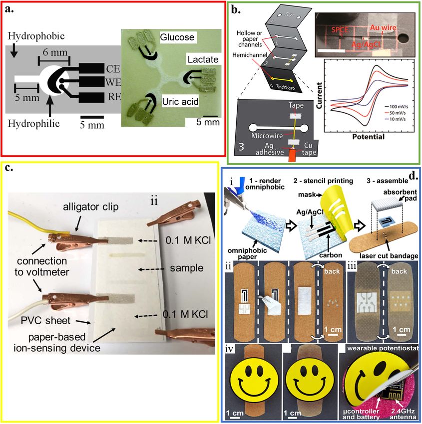
Micromachines 2020, 11, 243                                                                             2 of 34

hierarchically textured surfaces of the human body [20,21]. Therefore, the development of flexible
and stretchable electrochemical biosensors becomes attractive [22–28].
     The recent development in cost‐effective fabrication approaches includes various additive
manufacturing or printing technologies. Integrating electrochemical biosensors on soft substrates
with these approaches renders flexible and stretchable properties for wearable applications (Figure
1) [2,29–34]. Printing electrochemical sensing materials directly onto soft textiles of daily clothes
allows for timely monitoring of critical information, without compromising the level of comfort or
function of the garment [35–37]. However, textile‐based biosensors are limited to certain regions
because of the need for pliably conformal or intimate contact with biofluids for high‐fidelity
detection. Additionally, not all types of textiles are suitable to integrate sensing materials [38–40]. As
an alternative, other flexible thin‐film substrates (e.g., paper and plastic) have been explored [41–46].
However, the intrinsic fracture limit of the flexible thin‐film materials is small (e.g.,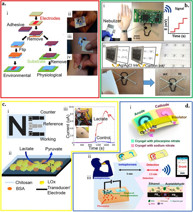
Micromachines 2020, 11, 243                                                                               3 of 34

     American Chemical Society; (m) interstitial fluid (ISF), reproduced with permission from [61],
     Copyright 2014, American Chemical Society, and (n) saliva, reproduced with permission from [62],
     Copyright 2012, Macmillan Publishers Limited.

     In this mini‐review, we summarize the latest development of wearable electrochemical
biosensors. Their working principles, target biofluids, fabrication approaches, and wearable
electrochemical biosensors based on various stretchable materials and structures are reviewed.
Following the introduction of the working principles of different electrochemical biosensors in
Section 2, we discuss the variety of target biofluids (e.g., sweat, tear, saliva, and interstitial fluids) for
wearable electrochemical biosensors to sample and analyze in Section 3. Next, Section 4 focuses on a
few representative cost‐effective fabrication approaches such as additive manufacturing or printing
to integrate electrochemical biosensors on various flexible and stretchable substrates, followed by a
conclusion and future perspective in Section 5.

2. Principles of Electrochemical Biosensors
     Electrochemical biosensors often consist of a recognition element and a sensor element (Figure
2). The recognition element could be the nucleic acid, antibody, ions, or enzyme. The sensing
element may rely on amperometry/voltammetry, potentiometry, field‐effect transistors, or
impedimetry [63–66]. These different types of electrochemical biosensors are also compared in Table
1 [64–67]. The transduced signals from the sensing element can be transmitted through a wired or
wireless communication module. The analysis of the data can then help inform the health condition.

     Figure 2. Schematic of electrochemical biosensors that include (a) a recognition element (e.g., nucleic
     acid, antibody, ions, or enzyme) and a detection transducer, along with a corresponding signal
     processing unit; reproduced with permission from [63]; Copyright 2016, The Royal Society of
     Chemistry. The detection transducer could be (b) amperometric/voltammetric sensors with i) two‐,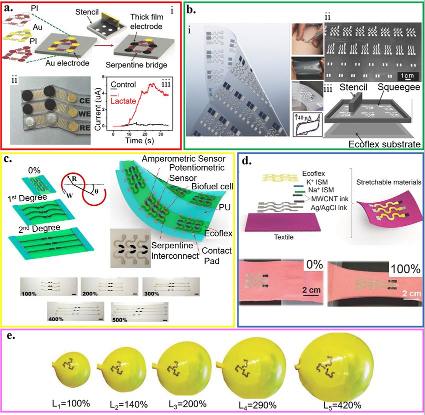
Micromachines 2020, 11, 243                                                                               4 of 34

     ii) three‐, or iii) four‐electrode configuration (reproduced with permission from [63]; Copyright 2016,
     The Royal Society of Chemistry), (c) a potentiometric sensor (reproduced with permission from [64];
     Copyright 2014, National Academy of Sciences), (d) a field‐effect transistor sensor (reproduced with
     permission from [65]; Copyright 2017, Elsevier), or (e) an impedimetric sensor (reproduced with
     permission from [66], Copyright 2008, Elsevier.) (f) Signal processing element that may include
     wireless communication module and processing units such as phones (reproduced with permission
     from [65]; Copyright 2017, Elsevier).

                Table 1. Summary of the working principles of different electrochemical sensors.

          Detection Mode                           Transducer                          Analytes
      Amperometric/voltammetric              Carbon, metal, chemically         Alcohols, glucose, phenols,
              sensors                          modified electrodes                       lactate
                                               Ion‐selective, carbon,
          Potentiometric sensors                                                     K+, Cl‐, Ca2+, Na+
                                               metal, glass electrodes
                                               Ion‐sensitive/enzyme
          Field‐effect transistors                                                         K+, H+
                                               field‐effect transistor
                                                Interdigitated/ metal
           Impedimetric sensors                                                   K+, helicobacter pylori
                                                     electrodes

2.1. Amperometric/Voltammetric Biosensors
       By probing the potential–current relationship, the amperometric or voltammetric biosensors
can detect electroactive species present in biological samples. In voltammetric biosensors, the
applied potential is varied to operate in either a linear or cyclic voltammetric mode. The target
analyte can be identified by the peak potential, whereas its concentration could be informed by the
peak current. By contrast with voltammetric biosensors, amperometric sensors relate the measured
current with the concentration of a specific analyte at a fixed potential. Other than the Faradaic
current from the reaction of the analyte, other sources of current also contribute to the measured
current (collectively referred to as the background current). The background current includes the
electrolysis of impurities, the electrolyte, and the electrode material, along with the capacitive
current from the electrode/solution interface. Operating the electrode at a fixed potential can help
eliminate the capacitive current. While the background current might be subtracted from the total
current in some cases [68–70], it can be challenging in other cases as the background current may
interact with the signal current in a non‐linear manner. The electrochemical system in a simple
amperometric/ voltammetric cell configuration could consist of a few from two to four electrodes,
i.e., a working, working sensing, counter, and reference electrodes (Figure 2a). In the amperometric
biosensor, gold, carbon, or platinum represents the common choice for the working electrode. These
electrode materials can provide good electron transfer towards the substrate in the reaction and
maintain high activation energy for electron transfer in the competing reactions. Ag/AgCl often
serves as the reference electrode to provide a fixed potential against which the potential of the
working electrode is controlled and measured. The two‐electrode configuration is simple. However,
it has limited control of the potential on the surface of the working electrode with large currents,
leading to a smaller linear range. To overcome this limitation, the counter electrode is employed to
provide a more stable potential reference in the three‐electrode configuration. In a four‐electrode
biosensor, redox recognition elements are immobilized on both the working and working sensing
electrodes. The proximity of two working electrodes enhances redox recycling that helps regenerate
electroactive species after their oxidation or reduction. Thus, this configuration is ideally suited for
micro‐scale interdigitated electrode arrays. Because redox recycling is only available with the redox
bio‐recognition element, four‐electrode systems are not as commonly used as their three‐electrode
counterparts. Amperometric/voltammetric biosensors with different configurations are commonly
used as immunosensors, enzyme biosensors, and pesticide monitors [71–74].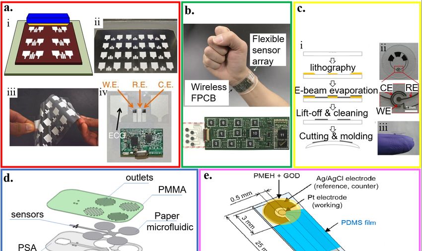
Micromachines 2020, 11, 243                                                                         5 of 34

2.2. Potentiometric Biosensors
      In potentiometric biosensors, an analyte recognition event is converted into a potential signal
for sensing (Figure 2b). Local equilibrium is established across the recognition membrane (e.g.,
ion‐selective members), leading to a change in the membrane potential. The information of the
analyte is obtained from the potential difference between the working and reference electrodes. The
most common potentiometric biosensors are capable of detecting pH, ions (e.g., F−, I−, CN−, Na+, K+,
Ca2+, or NH4+), and gas (e.g., CO2 or NH3). The potential differences between the working and
reference electrodes are proportional to the logarithm of the ion activity or gas fugacity (i.e., effective
partial pressure or concentration) [71–74]. Although potentiometric biosensors are simple, of low
cost, and highly selective, they have low sensitivity that limits their use in many applications [72]. In
addition to the contribution from the sensor response, the current response in potentiometric
biosensors also comes from the electrode double layer charging current that can be estimated by a
double‐layer capacitance model. The charging current is often considerable and difficult to remove
or filter out, thereby limiting the resolution of potentiometric sensors [73].

2.3. Field‐Effect Transistor (FET) Biosensors
     In the ion‐sensitive field‐effect transistors (ISFETs), an ion‐selective membrane is applied
directly to the insulated gate of the field‐effect transistors (Figure 2c). The ISFETs can also be used to
determine the corresponding ion concentrations. When such ISFETs are coupled with a biocatalytic
or biocomplexity layer, they become biosensors and are usually called either enzyme or
immunological field‐effect transistors (ENFETs or IMFETs). Unlike potentiometric and
amperometric biosensors that use an electrode transducer, the ISFETs’ transducer is the gate oxide
layer. The response of the ISFETs allows the output to be either the gate voltage or source‐drain
current by fixing one and measuring the other. The ISFET biosensors have been developed for
enzyme sensing, antigen–antibody binding reaction measurements, and DNA detection [71,73,75].

2.4. Impedimetric Biosensors
     Impedimetric biosensors measure the change in electrical impedance. This change often results
from changes in capacitance and/or resistance of bio‐interface characteristics for bio‐recognition
events. As a small sinusoidal stimulus voltage (or current) is imposed in a range of frequencies, the
resulting current (or voltage) is measured in the impedimetric biosensor. Thus, it can inform
bio‐recognition events from the obtained phase and/or amplitude changes. Compared to
potentiometric and amperometric biosensors, an important advantage of impedimetric biosensors is
that they do not damage or disturb most bio‐recognition events because of the applied stimulus
sinusoidal voltage is negligibly small (usually 5–10 mV in amplitude) [74].

3. Target Biofluids for the Wearable Electrochemical Biosensors
     Wearable electrochemical biosensors have been explored for human health monitoring through
the analysis of saliva, tear, sweat, and interstitial fluid (Figure 3). Table 2 compares the
representative electrochemical biosensors for these different target biofluids within the last five
years.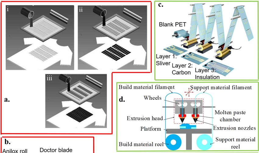
Micromachines 2020, 11, 243 6 of 34
Table 2 Summary of representative electrochemical biosensors with applications of biofluid analysis.
Recognition Response Linearity
Biofluid Platform Analyte Technique LOD detection sensitivity Ref.
element time range
2.32 μA /mM in artificial saliva
NR
PET Uricase enzyme Uric acid Amperometry 0−1.0 mM NR 1.08 μA/mM in undiluted human [76]
(real‐time)
saliva
NR 0.202 μA/mM in undiluted
PB LOx Lactate Amperometry 0.1−1.0 mM NR [77]
(real‐time) human saliva
Saliva NR
Foil Carbon (carboxymethyl)lysine Amperometry 0.5−10 μg/mL 0.8 μM NR [78]
(real‐time)
NR
polyester GOx Glucose Amperometry 0−1.0 mM 5 μM 41.7 μA∙mM−1∙cm−2 [79]
(real‐time)
NR
PETG GOx Glucose Amperometry 0.1−1.0 mM NR NR [80]
(real‐time)
10 μM–100
Amperometry NR 5 μM NR [81]
mM
PET GOx Glucose Amperometry 35 s 0−100 μM 50 μM 53 μA∙mM−1∙cm−2 [82]
Tear NR
Amperometry 0.1−0.6mM NR NR [83]
(real‐time)
NR
Polyethylene CuO Glucose Amperometry 0–0.7 mM 2.99 μM 850 μA∙mM−1∙cm−2 [84]
(real‐time)
NR 0.05 to 0.3
PET Carbon ink Glucose Amperometry NR 10.89 μA∙mM–1∙cm–2 [85]
(real‐time) mM
NR 0.05
Tattoo Carbon ink Zinc Amperometry 20−100 mM 23.8 μA mL/μg [86]
(real‐time) μg/mL
10−6 M to 10−1 4.02 × 10⁻⁷
Carbon fibres CNT ink Na+ Potentiometry NR 0.19 mV/decade [87]
Sweat M M
PET GOx Glucose Amperometry NR NR 10 × 10−6 M 41.8 nA∙μm−1∙cm−2 [88]
Polycarbonate LOx Lactate Amperometry NR NR NR 0.2 mM [89]
NR
LOx Lactate Amperometry 1−20 mM NR 0.1031 μA∙mm−2∙mM−1 [60]
Tattoo (real‐time)
ETH 129, PANI Ca2+, pH Potentiometry NR NR NR 32.2 mV/decade, 62.5 mV/decade [90]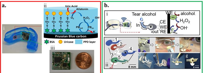
Micromachines 2020, 11, 243                                                                                                                                                                     7 of 34

                                                                                                          (real‐time)
                                                                                                              NR
                      PDMS                 GOx                     Glucose            Amperometry                             0−1 mM             NR                         NR                     [91]
                                                                                                          (real‐time)
  Interstitial
                      Tattoo               GOx                     Glucose            Amperometry             NR            0−0.16 mM            NR                         NR                     [92]
     fluid
       NR: not reported; LOD: limit of detection; PET: polyethylene terephthalate; PB: polybutylene; PETG: polyethylene terephthalate Glycol; ETH 129: a thin organic membrane containing electrically
       neutral carrier calcium ionophore II; PDMS: polydimethylsiloxane; CNT: carbon nanotube; PANI: polyaniline; GOx: glucose oxidase; LOx: lactate oxidase.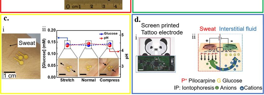
Micromachines 2020, 11, 243                                                                                 8 of 34

     Figure 3. Application of wearable electrochemical biosensor for biofluid analysis. (a) Saliva analysis
     from i) a mouthguard biosensor integrated with a wireless amperometric circuit board. ii) Schematic
     of reagent layer of the chemically modified, printed Prussian Blue (PB) carbon working electrode
     containing uricase for the salivary uric acid (SUA) biosensor and iii) optical image of the wireless
     amperometric circuit board; reproduced with permission from [76], Copyright 2015, Elsevier. (b)
     Tear analysis by (i) an eyeglasses platform consisting of wireless electronics and a fluidic device with
     (ii) its exploded view that shows (1) top polycarbonate membrane, (2) double‐adhesive spacer, (3)
     paper outlet, (4) electrochemical (bio)sensor, and (5) bottom polycarbonate membrane; reproduced
     with permission from [93], Copyright 2019, Elsevier. (c) Sweat analysis from i) an electrochemical
     biosensor attached to the skin wet with sweat, along with ii) its performance under mechanical
     deformation; reproduced with permission from [85], Copyright 2018, American Chemical Society.
     (d) Interstitial fluid (ISF) analysis that relies on i) a screen‐printed glucose biosensor and a wireless
     flexible printed circuit board, with schematic illustrations of ii) iontophoretic operation and layout of
     glucose biosensor; reproduced with permission from [92], Copyright 2018, Wiley‐VCH.

3.1. Saliva Analysis
     Human saliva is a watery substance that contains 99.5% water with electrolytes, mucus, white
blood cells, epithelial cells, glycoproteins, enzymes, among others [94]. By leveraging the
developments of biosensors, glucose and lactate in saliva can be non‐invasively monitored by a
cavitas sensor from the oral cavity. A wearable biosensor on a mouthguard is developed to monitor
salivary lactate [77]. The fabrication starts with the printing of Ag/AgCl as the reference electrode
and contacts (for interfacing the electrochemical analyzer) on a flexible PET substrate. Next, the
Prussian Blue (PB)‐graphite ink and LOx are coated on the working electrode (without LOx for the
counter electrode), followed by a coating of an insulation layer. The resulting lactate sensor
demonstrates high sensitivity of 0.553 μA∙mM−1 and a low limit of detection 0.050 mM. Building on
this work, a mouthguard electrochemical biosensor using the enzyme (uricase)‐modified electrode
from screen‐printing along with an integrated wireless amperometric circuitry detects salivary uric
acid with high sensitivity of 2.32 μA/mM (Figure 3a) [76].
Micromachines 2020, 11, 243; doi:10.3390/mi11030243                           www.mdpi.com/journal/micromachines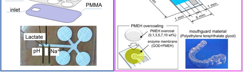
Micromachines 2019, 10, x                                                                          9 of 34

     By using non‐toxic serine amino acid as linker molecules for the functionalization of nZrO2, a
label‐free and non‐invasive biosensing platform can efficiently detect microRNA, an oral cancer
biomarker [63]. This sensor has a low limit of detection of 0.01 ng/mL that is sufficient for the lower
secretion level of targets in human saliva. And the biosensor also exhibits a linear detection range
0.01–29 ng/mL with a sensitivity of 0.295 μA mL/ng, along with a response time of 6 min and
long‐term stability up to 45 days. While the monitoring of saliva is of high interest for healthcare,
significant challenges still exist for the saliva electrochemical biosensors. The complicated mixture in
the saliva requires the sensor to be highly selective. The sensor also needs to maintain stable
performance in such a high moisture environment. Additionally, the devices should be fully
biocompatible due to the use in the mouth.

3.2. Tear Analysis
      Electrolytes, metabolites, lipids, and proteins/peptides are widely available in the complex
extracellular fluid of tears secreted from lacrimal glands, ocular surface epithelial cells, goblet cells,
and blood [95]. Through electrochemical biosensor applications, these complex extracellular fluids
can be measured for desirable health monitoring analyses [59,82,95,96]. As a natural choice, a contact
lens can integrate an amperometric glucose sensor to analyze the tear. Firstly, the sol‐gel titania film
is applied to immobilize GOx. Next, Nafion is used to decrease interference from the other analytes
in the tear to result in a glucose sensor with a fast response of 20 s and high sensitivity of 240
μA/(cm2∙mM). Integrating the sensor with power supply and wireless signal transduction to a
remote electronic device further provides a wireless sensor. The contact lens biosensor is used to
wirelessly monitor tear glucose in a rabbit ranging from 0.03 to 5.0 mM [97]. The estimated basal tear
glucose of 0.11 mM is shown to have a delay of 10 min from the blood sugar level. Without using
enzymes, modifying the electrodes with CuO microparticles from inkjet printing leads to an
enzyme‐free glucose tear sensor with a high sensitivity of 850 μA∙mM−1∙cm−2 and a low limit of
detection of 2.99 μM [84]. Besides, ocular contact lenses should not obstruct the field of vision. Thus
a highly transparent, multifunctional glucose sensor utilizing graphene and its hybrid with metal
nanowires on an actual ocular contact lens is developed [98,99]. With a stretchability of 25% and
high transparency of >91%, the sensor has demonstrated its reliable operation through both in vitro
and in vivo tests by using a bovine eyeball and living rabbit, respectively. Without the need for
direct eye contact, integrating wearable sol‐gel tear biosensor on an eyeglasses nose‐bridge pad
connected to eyeglasses to collect and analyze tear can enable non‐invasive monitoring (Figure 3b)
[93].

3.3. Sweat Analysis
     Compared to saliva and tear, sweat that contains abundant biochemical compounds can be
monitored from a wider range of locations on the human body. With a temperature sensor for
internal calibration, analysis of sweat with a constant flow yields simultaneous and selective
measurements of metabolite (e.g., lactate) and electrolytes (e.g., pH, Na+) [100]. The trace metal in
sweat can also be detected by a wearable amperometric biosensor. This biosensor consists of an
Ag/AgCl pseudo‐reference, counter, and carbon working electrode modified by Nafion and bismuth
for Zn detection. It owns a sensitivity of 23.8 μA∙mL/μg and a limit of detection of 0.05 μg/mL [60].
After preparing patterned Au nanosheets (AuNS) on a stretchable silicon substrate by filtration,
deposition of carbon nanotubes (CNTs) is followed by coating of CoWO4/CNT (of polyaniline/CNT)
nanocomposites on the electrode to result in a skin‐attachable electrochemical biosensor for
detecting glucose (or pH) in sweat (Figure 3c) [85]. Besides a sensitivity of 10.89 μA/(mM∙cm2) (or
71.44 mV/pH) for glucose (or pH), the sensors are also stable in air for 10 days and against
mechanical deformation with a tensile strain up to 30%. As sweat rates could vary with body
movements (e.g., running vs. sitting), it is highly desirable for sweat sensors to deconvolute multiple
components in the complex mixture of sweat at different rates.

3.4. Interstitial Fluid (ISF) Analysis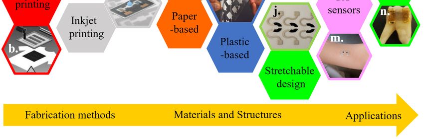
Micromachines 2019, 10, x                                                                        10 of 34

     Interstitial fluid (ISF) has a similar composition to that of blood. Each contains essential small
molecules (e.g., salts, proteins, glucose, and ethanol). Additionally, it can allow for minimally
invasive monitoring without the need for blood sampling [101]. By applying a potential difference
between two electrodes on the skin surface, reverse iontophoresis extracts ions such as Na+ in the ISF
to the skin surface [102,103], which has also been used by the GlucoWatch [104]. Combining reverse
iontophoresis with an enzyme‐based amperometric biosensor results in a flexible tattoo‐based
epidermal diagnostic device (Figure 3d) [92]. Compared to GlucoWatch, a GOx‐modified Prussian
Blue transducer at a low applied potential analyzes the ISF glucose extracted by reverse
iontophoresis at a low current density. Non‐invasive extraction of the ISF from the subcutaneous
tissue can also be enabled by a PDMS‐based microfluidic system. This system consists of a micro
vacuum generator for transdermal ISF extraction, microchambers for ISF collection,
micro‐pneumatic valves for fluid management, and a microflow sensor for ISF volume measurement
with an error
Micromachines 2019, 10, x 11 of 34
In addition to the template‐based printing methods, non‐template‐based printing technologies
have been developed because of their higher customization design and lower price for small‐scale
manufacturing. Non‐template‐based printing methods rely on dispensing the given technology.
These technologies include the use of gas or pressurized air (pneumatic), the use of piezoelectric
material in the setup (piezoelectric), the use of aerodynamic focusing (aerosol jet), the driving of ink
by an electric field (electrohydrodynamic), and the heating the material (thermal). [125,126]. As a
representative non‐template‐based printing method, extrusion‐based 3D printing applies the ink
filament through a heated nozzle onto the substrate via a computer‐controlled motion stage (e.g.,
three‐axis) to manufacture a fully 3D‐printed electrode (Figure 4d) [114]. By contrast with
extrusion‐based 3D printing that often requires high viscosity (>300 k cP) in the inks, inkjet printing
explores the low viscosity (10–20 cP) inks to help ink transfer (Figure 4e). However, low‐viscosity
inks suffer from small filler loading [115,125].
Figure 4. Template‐ (red boxes) and non‐template (green boxes) fabrication approaches. The
template fabrication approaches include (a) screen printing, (b) flexographic process, and (c) gravure
printing. The screen printing explores i) laser‐cut stainless steel or chemically‐etched polymeric
mesh‐screen stencils for patterning ii) the Ag/AgCl reference and iii) working/counter electrodes
with carbon‐ or metal‐based ink containing recognition elements overlaid on the Ag/AgCl
conductor; reproduced with permission from [50], Copyright 2013, Wiley‐VCH. In the flexographic
process, the surface of the anilox roller consists of engraved cells. The doctor blade helps to remove
excess ink from the anilox; reproduced with permission from [112], Copyright 2017, Elsevier. By
using a rotary printing press in the gravure printing, the image is engraved onto a cylinder;Micromachines 2019, 10, x 12 of 34
reproduced with permission from [113], Copyright 2018, American Chemical Society. The
non‐template fabrication approaches include (d) 3D printing and (e) inkjet printing. In
extrusion‐based 3D printing, the build material filament is heated, melted, and extruded in the
nozzle. Each layer is deposited on the previous layer to form the designed 3D structure; reproduced
with permission from [114], Copyright 2016, Wiley‐VCH. In inkjet printing, layers of conducting and
dielectric materials are injected, patterned, and stacked on a substrate; reproduced with permission
from [115], Copyright 2015, Elsevier.
Table 3. Comparison of representative printing approaches for electrochemical biosensors.
Template printing Non‐template printing
Method Screen Gravure Flexography Inkjet 3D
printing printing printing printing printing
Ink viscosity
500–5000 100–1000 50–500 10–20 > 300 k
(cP)
Line width
50–100 10–100 45–100 2.3–50 1–100
(μm)
Line thickness
3–250 1Micromachines 2019, 10, x 13 of 34
glucose 100 × 10−9 M
NR
LOx Lactate Amperometry (real‐ti 1.0 μM Yes/No [142]
me)
Polyamide GOx Glucose Amperometry NR 0.1 mg/dL Yes/No [143]
NR
PEN LOx Lactate FET (real‐ti 66 nM Yes/No [144]
me)
NR
GOx Glucose Amperometry (real‐ti 0.010 mM Yes/No [145]
Polyurethane
me)
LOx Lactate Amperometry 50 s NR Yes/No [146]
Carbon ink pH Potentiometry 10 s NR Yes/No [147]
Ionselective
Potentiometry 5s 10−4.9 M Yes/No [148]
membranes Ammonium
Water
Tattoo Yes
Silver ink content Impedimetry NR NR Yes/No [67]
(hydration)
Alcohol
Ethanol Potentiometry 30 s NR Yes/No [149]
oxidase
FET: field‐effect transistor; PAN: polyacrylonitrile; HRP: horseradish peroxidase; NR: not reported.
4.2. Textile‐Based Biosensors
Being flexible and widely used in our daily life, textiles such as wool, cotton, and nylon have
been extensively exploited as the substrate for integrating various electrochemical biosensors [150].
Early investigations of textile‐based chemical biosensors rely on optical systems for bio‐sensing. This
is through the utilization of a light source and detector [35–37]. However, the required optical
sensors are sophisticated and high in cost. By leveraging the recently developed fabrication
techniques, simple textiles‐based electrochemical biosensors have been obtained to withstand
repeated bending cycles. The influence of textile substrates (e.g., cotton, polyester, and widely used
breathable and water‐proof GORE‐TEX® fabric) on the sensing performance of nitroaromatic
explosives has been investigated when integrated screen‐printed electrodes on different textile
substrates [118]. The adhesion at the electrode/textile interface is demonstrated to be robust against
cycles of laundry washing and mechanical deformations.
Applying the technique of screen printing yields a highly stretchable textile‐based biofuel cell to
analyze sweat metabolites (Figure 5a) [54]. The glucose (or lactate) biofuel cell with single‐enzyme
and membrane‐free configurations could generate a maximum power density of 160 (or 250) μW
cm−2 with an open‐circuit voltage of 0.44 (or 0.46) V. Enzymatically oxidized on the anode, the
biofuel (e.g., glucose) releases electrons that are accepted by the cathode. The generated power can
operate on human‐body sweat to provide a self‐powered response. Intrinsically stretchable inks (i.e.,
CNTs dispersed in Ecoflex) and stretchable structure of the serpentine electrode are employed in the
device. The resulting self‐powered devices can exhibit a high stretchability (a tensile strain of 100%)
and endure a stable performance upon repeated (>100 times) strains. An alternative wearable,
high‐power biofuel cell explores a glucose‐oxidizing glucose dehydrogenase as anode and an
O2‐diffusion bilirubin oxidase as a cathode on a textile cloth (Figure 5b) [151]. Two types of CNT
layers are used to improve the performance of the anode and cathode: an acid‐treated hydrophilic
CNT layer for coating of the mediator and enzyme, and polytetrafluoroethylene (PTFE)‐based
hydrophobic CNT layer for adequate oxygen diffusion by forming a microporous layer. Owning to
the stretchable material and structure, the maximum power density can still maintain 216 μW/cm2 at
an output voltage of 0.36 V for glucose of 200 mM even upon deformation (e.g., S‐shape). By using a
series connection of four biofuel cell, power can be generated with an open‐circuit voltage of 1.9 V to
illuminate a light‐emitting diode (LED) on the cloth.
Compared to the integration of electrodes on the textile with a conventional screen‐printing
method that results in ink waste, embroidery and yarn coating use only as much reagent and ink asMicromachines 2019, 10, x 14 of 34
required. Conductive threads with the immobilized enzyme can be embroidered into textiles to
serve as the working, counter, and reference electrodes in an electrochemical biosensor with
three‐electrode configuration to quantitatively analyze biofluid samples (Figure 5c) [133]. The
electrodes with customized geometries at specific locations on a garment can be quickly fabricated
by using a computerized embroidery machine. The hydrophilic nature of most threads in
embroidered sensors can help quickly absorb liquids to facilitate sample loading for improved
automation. The embroidered electrochemical biosensor exhibits a stable performance with a
marginal decrease of 9% in the signal after 100 bending cycles. Multiplexed measurements of
different targets (e.g., glucose and lactate) can also be achieved by using selective assays to each
target (e.g., a glucose assay and a lactate assay). With negligible signals from the non‐specific
analytes, the glucose (or lactate) assay only selectively responds to the glucose (or lactate) with a
significant response and a high signal‐to‐noise ratio of 3.2 (or 4.1) at a concentration of 5 mM (or 12.5
mM). Similar to embroidery, yarn coating allows the use of textile weaving with a wide variety of
yarn materials, weaving styles, and looms to create electrochemical biosensors with various
properties. For instance, silk yarns coated with conducting inks can be handloom‐woven as
electrodes into patches of fabric to create arrays of sensors, which are then laminated, cut, and
packaged into individual sensors. By using the sensor consisting of four electrodes with one
working electrode for hemoglobin and one working electrode for glucose, a multiplexed array can
simultaneously detect glucose and hemoglobin from the blood samples (Figure 5d) [152]. While the
use of an analyte‐specific enzyme (i.e., glucose oxidase) on the working electrode provides a highly
selective glucose detection, the carbon electrode with differential pulse voltammetry (DPV) detects
hemoglobin with no significant interference from glucose. The shared counter and reference
electrodes in the multiplexed sensor also help reduce the cost.
As an alternative to the weaving/embroidery of conducting fabric or integration of other
conductive materials, the carbonization of textiles coated with nanomaterials presents another route
to the creation of the electrochemical biosensors. In a representative example, silk fabrics coated with
multi‐walled carbon nanotubes to fully use the space and strengthen the interconnection are first
carbonized from hydrophilic to relatively hydrophobic. Decorating the resulting structure with Pt
microspheres (or glucose oxidase, GOx) enables the detection of H2O2 (or glucose) (Figure 5e) [153].
The glucose sensor obtained has a sensitivity of 288.86 μA/(mM cm2) in a relatively good linear
range from 0 to 5 mM. As the intimate contact between the sensor and skin is highly desirable to
allow for the precise measurement of the target analyte, tight‐fit clothing has been explored. As a
representative example, textile‐based amperometric biosensors are integrated on an elastic
waistband of common underwear for direct tight contact [31]. However, the level of comfort is
significantly compromised. Additionally, measurements of analyte concentrations are limited to
specific locations that have intimate contact between textile‐based devices and the skin [38].
Therefore, thin‐film sensors based on the other flexible and stretchable substrates have been
developed to address some of these concerns.Micromachines 2019, 10, x 15 of 34
Figure 5. Fabric‐based electrochemical sensors. (a) Optical images of the designed stencil and its use
for printed stretchable devices through a screen printing process; reproduced with permission from
[54], Copyright 2016, The Royal Society of Chemistry. (b) i) Schematic of enzyme/carbon nanotube
(CNT) composite fibers woven on a textile cloth. The anode and cathode fibers were prepared by
modifying multi‐walled CNT‐decorated carbon fibers with glucose dehydrogenase and bilirubin
oxidase, respectively. ii) Illumination of a light‐emitting diode (LED) device consisting of a charge
pump IC, capacitor, and red LED connected to enzymatic power fibers upon dropping a glucose
solution on a cloth; reproduced with permission from [151], Copyright 2019, Elsevier. (c)
Embroidered electrochemical sensors fabricated on textile, cotton gauze, and cotton t‐shirt;
reproduced with permission from [133], Copyright 2016, The Royal Society of Chemistry. (d)
Manufacturing of fabric‐based electrochemical sensors: i) custom‐made yarn coating instrument, ii)
handloom used to weave the sensors, iii) woven patches on the loom, and iv) a woven array of 90 (15
× 6) sensors; reproduced with permission from [152], Copyright 2015, The Royal Society of
Chemistry. (e) Schematic of processes to prepare the glucose sensor based on the carbonization of
textiles; reproduced with permission from [153], Copyright 2018, Elsevier.
4.3. Flexible Thin‐Film Biosensors
4.3.1. Paper‐Based Biosensors
Being flexible, foldable and rollable, widely available, inexpensive, lightweight, and
hydrophilic, paper can be readily and rapidly modified with biomolecules and nanomaterials for
electrochemical‐sensing applications. The high porosity of cellulose in the paper also allows for
solution transport through capillary forces. It can serve as an autonomous microfluidic pumping
system without a need for external pumps [154]. The paper‐based bioanalytical devices use capillary
forces to drive the lateral flow of a liquid sample (i.e., lateral flow immunochromatographic assays
or lateral flow tests) [155,156]. Based on the generated color, lateral flow tests can provide qualitativeMicromachines 2019, 10, x 16 of 34
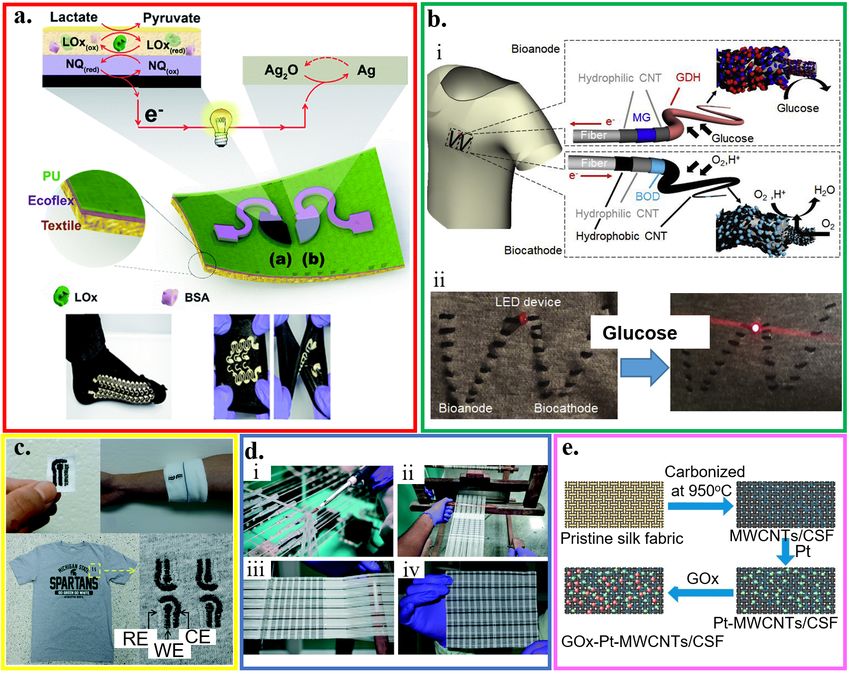
or semi‐quantitative information [157]. Quantitative measurements can also be obtained with
electrochemical paper‐based analytical devices (ePADs) that use the photolithography to create
microfluidic channels on the filter paper (Figure 6a) [55]. The Ag/AgCl ink is first applied as the
reference electrode and conductive pads. Next, screen‐printing carbon ink that contains Prussian
Blue results in the working and counter electrodes. Spotting the analyte‐specific enzymes (e.g., GOx,
lactate oxidase or LOx, and uricase) helps determine the concentration of glucose, lactate, and uric
acid, with a limit of detection of 0.21 ± 0.02 mM, 0.36 ± 0.03 mM, and 1.38 ± 0.13 mM, respectively. As
a close distance between the working and reference electrodes minimizes the effect from
uncompensated resistance between the two electrodes, screen printing that requires a stencil to
pattern the electrodes limits the achievable maximum resolution [157–160].
Although the shape of electrodes is well‐defined with a patterned screen or stencil, they often
suffer from poor electrical properties and irreproducible surface chemical properties. As an
alternative, prefabricated Au microwires and carbon fibers, along with their meshes, can be
exploited as electrodes in a paper‐based device with a multilayered structure created by the folding
principles of origami (Figure 6b) [161]. When a large surface area is desirable, mesh electrodes are
preferred over their wire counterparts to provide a larger surface area for the immobilization of
bioprobes. Without using a patterned screen or stencil, portable writing tools such as lead pencils
can directly draw electrodes with the desired geometry on paper to create electrochemical devices
[162]. After pressurization, the mixture consisting of carbon powder as a conductive material,
sodium bentonite as a binding agent, and sodium silicate as a hardening agent in thin rods can be
inserted in commercial lead holders to facilitate drawing on paper.
With precise control of ink droplet volume, inkjet printing has also been explored to fabricate
paper‐based electrochemical biosensors [163]. In the inkjet printing paper‐based electrochemical
biosensor with a three‐electrode configuration [164], the electrochemical deposition of Ag/AgCl on
an inkjet‐printed Ag nanoparticle pattern serves as the reference electrode. After inkjet‐printing of
nanoparticle‐based gold working and counter electrodes, electropolymerized polyaniline (or GOx
entrapped poly‐3,4‐ethylenedioxythiophene) films on the surface of the working electrode enable
selective sensing of pH (or glucose), which has comparable performance with their commercial
counterparts. Applying inkjet printing can also integrate a potentiometric cell into a piece of filter
paper to form a paper‐based ion‐selective platform (Figure 6c) [165]. This device uses a hydrophilic
high‐capacity ion‐exchange membrane and a valinomycin‐doped ion‐selective electrode (ISE)
membrane embedded into the paper. It achieves highly selective sensing of Cl− and K+ with a
sensitivity of 57.4 ± 0.5 mV/decade and 53.3 ± 0.7 mV/decade, respectively.
Integrating paper‐based biosensors with other platforms such as a commercial bandage may
open additional opportunities, such as a smart bandage. The screen‐printed conductive inks are
embedded into commercial bandages. The developed omniphobic paper‐based smart bandage
(OPSB) with a lightweight (~8 g) sensor is capable of measuring pH and uric acid in open wounds
and pressure ulcers for chronic wound monitoring (Figure 6d) [166]. Taken together with a wireless
communication module, the wearable OPSB can simultaneously quantify pH and uric acid levels at
the wound site to wirelessly inform the user of wound status [167] at low‐cost (~$18).Micromachines 2019, 10, x 17 of 34
Figure 6. Paper‐based electrochemical biosensors. (a) Design and optical image of the
electrochemical detection cell for paper‐based microfluidic devices. WE/CE: working/counter
electrode (carbon ink); RE: reference electrode (silver/silver chloride ink); reproduced with
permission from [55], Copyright 2009, American Chemical Society. (b) Paper‐based
microelectrochemical devices with electrodes based on conductive wires, inlet/outlet in the 1st layer,
and two stacked channels in the other 3 layers; reproduced with permission from [161], Copyright
2014, American Chemical Society. (c) Optical image of a paper‐based ion‐sensing platform, with two
alligator clips on the left to measure the electromotive force (EMF) and two clips on the right for
balancing; reproduced with permission from [165], Copyright 2016, WILEY‐VCH. (d) Fabrication
and assembly process of omniphobic paper‐based smart bandage (OPSB): (i) Schematic of the
fabrication of OPSBs: 1) After spraying RFSiCl3 of 2% in IPA to render Whatman #1 paper
omniphobic, 2) flexible carbon and Ag/AgCl electrodes are patterned through stencil printing,
followed by 3) laser‐cutting the adhesive layer of the bandage for creating openings to interface with
the wearable potentiostat. Placing the paper‐based sensors between the adhesive layer and the
absorbent pad of the commercial bandages assembles the OPSBs, which can monitor (ii) uric acid
and pH levels in open wounds, as well as (iii) the early detection of pressure ulcers. (iv) shows the
packaging of the electronics in the rechargeable, wearable potentiostat; reproduced with permission
from [166], Copyright 2018, Elsevier.Micromachines 2019, 10, x 18 of 34
4.3.2. Plastic‐Based Biosensors
Compared to paper, plastic substrates (e.g., polyester family, polyethylene naphthalene,
polytetrafluoroethylene, and many others) have sufficient thermal stability, low coefficient of
thermal expansion, and structural resiliency against deformation [125]. By using the widely reported
flexible polyester with a thickness of 50 μm as a representative example [82,168–170], a
three‐electrode amperometric lactate biosensor is fabricated along with a bipolar electrocardiogram
sensor in a wearable hybrid sensing system (Figure 7a) [56]. The three amperometric electrodes are
also separated from the Ag/AgCl electrocardiogram electrodes via a printed hydrophobic layer to
increase sensor stability and signal‐to‐noise ratio. The working electrode of the lactate biosensor is
coated with LOx‐modified Prussian Blue as a biocatalytic layer for selective detection of lactate,
which has a sensitivity of 96 nA/mM in a linear range for the lactate concentration from 0 to 28 mM.
As a representative example in the polyester family, the polyethylene terephthalate (PET) substrate
has also been widely explored for the thin‐film sensors. For instance, a mechanically flexible and
fully integrated sensor array can also be embodied on the PET substrate for multiplexed in situ
perspiration analysis (Figure 7b) [22]. The integrated sensor array can simultaneously and
selectively measure sweat metabolites (glucose and lactate) and electrolytes (sodium and potassium
ions), along with the skin temperature to calibrate the response of the other sensors. Molding a 100
μm‐thick PET into a contact lens shape allows for the integration of sensors to detect lactate with an
average sensitivity of ∼53 μA/(mM cm2) within the linear range from 0 and 1 mM and a relatively
fast response time of 35 s (Figure 7c) [82].
A flexible hybrid poly(methyl methacrylate) (PMMA)/paper microfluidic platform with fully
integrated sensing can simultaneously monitor lactate, Na+, and pH for on‐body testing of human
sweat (Figure 7d) [171]. A continuous flow of sweat is collected by microneedles with an array of Pt
and Ag wires (50 μm diameter) and transported in a paper microfluidic channel. The Pt and Ag wire
microneedles also serve as the working and reference electrodes for the lactate/ Na+/pH sensors.
Before drop‐casting LOx on the working electrode in the amperometric‐based lactate sensor, a
semipermeable copolymer membrane (sulfonated polyether ether sulphone‐polyether sulphone,
SPEES/PES) is applied to achieve high selectivity, following by a coating of an outer polyurethane
layer. The pH sensor relies on a pH‐sensitive iridium oxide (IrOx) membrane to yield a sensitivity of
71.90 ± 0.8 mV/unit. And the potentiometric Na+ sensor exploits a bilayered structure with polyvinyl
chloride (PVC) membrane on a poly(3,4‐ethylenedioxythiophene) (PEDOT) polymer to result in a
sensitivity of 56 ± 1 mV/unit.
Because of its strong adhesion to Pt and Ag, PET glycol (PETG) is used as the platform (e.g.,
PETG mouthguard) to integrate Ag/AgCl reference electrode and Pt working electrode with GOx
immobilized by poly (MPC‐co‐EHMA) (PMEH) for monitoring saliva glucose (Figure 7e) [172]. By
using a 1.0 wt% PMEH overcoat and an electrode surface area of 16.8 mm2, optimized glucose
measurement in artificial saliva with a phantom jaw is achieved with a stable response within ~60 s
and good sensitivity for the glucose concentration from 0.05 to 1.0 mM.Micromachines 2019, 10, x 19 of 34
Figure 7. Plastic‐based wearable electrochemical biosensors. (a) i) Schematic and ii) optical image of
the fabrication of the electrochemical sensor through screen printing, as well as iii) its flexibility
demonstration and iv) integration with the wireless electronics; reproduced with permission from
[56], Copyright 2016, Macmillan Publishers Limited. (b) Optical image of a wearable flexible
integrated sensing array (FISA) on the wrist of a subject; reproduced with permission from [22],
Copyright 2016, Macmillan Publishers Limited. (c) i) Fabrication process and ii‐iii) optical images of
a lactate sensor on the contact lens with sensing structure on ii) a flat substrate and iii) a completed
contact lens held on a finger; reproduced with permission from [82], Copyright 2012, Elsevier. (d)
Exploded view and optical image of the microfluidic chip with microneedles for sweat collection
and analysis. The sensors were placed inside the microfluidic channel that could draw a continuous
flow of sweat; reproduced with permission from [171], Copyright 2017, Elsevier. (e) Schematic and
optical image of the glucose biosensor on the polyethylene terephthalate glycol (PETG)
mouthguard, with Pt and Ag electrodes formed by a sputtering process; reproduced with
permission from [172], Copyright 2016, Elsevier.
4.3.3. Temporary Tattoo‐Based Biosensors
Tattoo‐like electrochemical biosensors are attractive because of their intimate contact with the
human skin without causing much discomfort on the body [2,173]. In fabricating temporary transfer
tattoo‐based electrochemical biosensors (Figure 8a) [57], the electrode designed in red with active
ink materials (e.g., carbon and Ag/AgCl reinforced with carbon fibers) is first patterned by screen
printing on paper (orange) coated with the release agent (olive). After applying the adhesive sheet
(blue) with a protective coating (maroon) on the printed sensor, removing the protective sheet andMicromachines 2019, 10, x 20 of 34
flipping the layers can apply it onto the skin (green). Removing the release agent‐coated paper then
exposes the sensor. Before removing the protective sheet, the release agent‐coated paper can be
removed to allow direct contact of the electrode to the skin. In addition to favorable electrochemical
properties as opposed to the electrodes from the conventional screen printing, the resulting sensor
also exhibits robust performance against various deformation modes (e.g., pinching, bending, and
twisting), with promising applications as potentiometric and amperometric sensors
[60,147,148,173–177].
The accuracy of conventional potentiometric biosensors hinges on a stable and reproducible
potential of the liquid junction at both reference and working electrodes. However, the leakage of
the solution becomes a concern [38]. By exploring the concept of all‐solid‐state electrodes [147,148], a
wearable potentiometric all‐solid‐state biosensor (without inner liquids) is developed for real‐time
on‐body monitoring of nerve agents simulant diisopropyl fluorophosphate (DFP) (Figure 8b) [175].
The enzymatic hydrolysis of DFP by the enzyme of organophosphate hydrolase (OPH) results in
proton release. The resulting pH change captured by the skin‐worn potentiometric pH‐sensing
transducer directly correlates to the DFP in the liquid and gas phases. The device in the design of a
“skull face’’ layout consists of one ‘eye’ from an Ag/AgCl reference electrode and the other ‘eye’
from a printed carbon working electrode coated with polyaniline (PANI). The sensor can detect the
DFP in the liquid phase with a limit of detection of 10 mM and a stable response in less than 20 s for
the concentration from 10 to 120 mM. The detection of the DFP in the vapor phase is slightly longer
but still within 30 s. With the same limit of detection of ~10 mM, the sensor response increases
linearly as the vapor concentration increases from 20 to 120 mM.
By using a mediated LOx working electrode in an amperometric biosensor, the printed
temporary‐transfer tattoo electrochemical biosensor enables real‐time lactate sensing (Figure 8c)
[60]. The LOx working electrode is prepared by first tethering the LOx enzyme on the surface of the
printed tattoo electrode functionalized with tetrathiafulvalene and multiwalled carbon nanotubes.
Next, a biocompatible chitosan overlayer is coated. The resulting sensor exhibits a high sensitivity of
10.31 μA/(mM cm2), a very good specificity with negligible responses from interfering agents (e.g.,
ascorbic acid, uric acid, glucose, and creatinine) of less than 5%, and a highly linear response for the
lactate concentration ranging from 1 to 20 mM.
Combining reverse iontophoresis (RI) to extract interstitial fluid (ISF) glucose to the skin surface
results in a tattoo‐based noninvasive glucose monitoring system [61]. This enzymatic amperometric
biosensor has a similar principle of the GlucoWatch glucose sensor. The device system has one pair
of the anodic and cathodic contingents, with each consisting of a group of working, counter, and
reference electrodes encompassed by an additional Ag/AgCl RI electrode for efficient extraction of
ISF. The glucose tattoo sensor exhibits a sensitivity of 23 nA/μM and a limit of detection of 3 μM, and
a linear response range from 0 to 100 μM. Exploiting two iontophoretic electrodes (anode and
cathode) with three amperometric sensing electrodes (working, reference, and counter electrodes) in
the anode compartment can also yield a wearable alcohol sensor system (Figure 8d) [46]. By
delivering the pilocarpine drug from the anode compartment, iontophoretic electrodes induce the
sweat in the anode region for the alcohol analysis with a high sensitivity to detect ethanol (0.362 ±
0.009 μA/mM). Because of the use of alcohol oxidase, the alcohol sensor demonstrates negligible
interferences from glucose, uric acid, lactate, ascorbic acid, and creatine.Micromachines 2019, 10, x 21 of 34
Figure 8. Temporary tattoo‐based wearable electrochemical biosensors. (a) i) Schematic and ii‐iv)
optical images of the processes to prepare temporary transfer on‐skin tattoo‐like electrochemical
sensor; reproduced with permission from [57], Copyright 2012, The Royal Society of Chemistry. (b)
Tattoo‐like biosensor for detecting nerve agents: i) Image of the integrated potentiometric biosensor
system placed on the mannequin for wireless signal transmission with schematics to show ii) sensors
printed on the tattoo paper and optical images to show iii) sensors transferred to the skin after
removal of the protective layer; reproduced with permission from [175], Copyright 2018, Elsevier. (c)
i) Schematic illustration of a three‐electrode “NE” tattoo‐like electrochemical sensor to detect
epidermal lactate, with its ii) working principle and iii) demonstration of sweat lactate monitoring
during cycling exercise; reproduced with permission from [60], Copyright 2013, American Chemical
Society. (d) Tattoo‐based transdermal alcohol sensor. i) Schematic diagram of an
iontophoretic‐sensing tattoo‐like device for transdermal alcohol sensing, as well as schematic
diagrams to show ii) its wireless operation and iii) constituents in the iontophoretic system;
reproduced with permission from [46], Copyright 2016, American Chemical Society.Micromachines 2019, 10, x 22 of 34
4.4. Stretchable Thin‐Film Biosensors
Flexible thin‐film biosensors can withstand a mechanical strain before fracture (e.g.,Micromachines 2019, 10, x 23 of 34
Figure 9. Wearable electrochemical biosensors based on stretchable structures. (a) i) Schematic of the
fabrication processes that merge lithographically fabricated thin‐ and printed thick‐film for a hybrid,
stretchable electrochemical sensor, along with ii) an image of the stretchable lactate sensor (working,
reference, and counter electrodes) and iii) its demonstration for real‐time on‐body amperometric
evaluation of lactate levels from a subject with (red) and without (black) enzyme modification;
reproduced with permission from [192], Copyright 2017, Wiley‐VCH. (b) i) Optical image and ii)
fabrication process of different patterns of interconnects that connect electrodes and contact pads by
printing inks through a stencil with (iii) a schematic of the screen printing; reproduced with
permission from [188], Copyright 2015, Wiley‐VCH. (c) Combining stretchable serpentine structures
with intrinsically stretchable nanomaterial‐based inks results in highly stretchable electrochemical
sensors; reproduced with permission from [58], Copyright 2015, American Chemical Society. (d)
Schematic representation and optical images of the electrochemical sensors with stretchable
structures applied on stretchable textile substrates upon a tensile strain of 100%. The sensor was
fabricated by screen printing of stretchable Ag/AgCl ink, stretchable CNT ink, and Ecoflex layer,
followed by surface modification of ion‐selective membrane at specific locations; reproduced with
permission from [128], Copyright 2016, Wiley‐VCH. (e) Series of optical images to show different
inflation levels of the expandable electrochemical device; reproduced with permission from [189],
Copyright 2016, Wiley‐VCH.Micromachines 2019, 10, x 24 of 34
5. Conclusions and Future Perspectives
In this mini‐review, we have briefly summarized the recent development of flexible and
stretchable electrochemical biosensors for personal healthcare, which has experienced remarkable
growth over the past few decades. Integrating these sensors with affordable and advanced wireless
modules [194–196] results in functional devices that can continuously detect and analyze biofluids
such as saliva, tear, sweat, and interstitial fluid. Despite the significant strides achieved in the field of
electrochemical biosensors, several challenges still exist before their wide adoption in practical and
daily applications. First of all, effective sampling of biofluids from the body is crucial to ensure
accurate sensing results, necessitating the need for a biofluid sampling and collection module in the
system [197–199]. It is also highly desirable to improve the sensing performance of wearable
electrochemical biosensors. While significant efforts have been devoted to the development of
highly sensitive sensors, their response to various interfering factors in the complex biofluids cannot
be ignored, especially when a trace amount of target analyte is present. The deconvolution of
multiple components from a mixture by a high‐density array represents a promising approach to
address such a challenge [11].
The wearable electrochemical biosensors should also maintain stable performance with
minimal interfacial adhesion issues against washing or relatively high temperature. A possible
concern from the relatively high temperature is the damage of the sensor in a hot shower [189].
While there are plenty of strategies to achieve a high dry adhesion, robust wet adhesion is of more
relevance to the application of wearable electrochemical biosensors. The bioinspired materials (e.g.,
gelatin‐, collagen‐, or chitosan‐based materials) [200–202] have been studied and developed to
provide an improved wet adhesion [203]. Exploring these materials can achieve stable binding
between functional layers (e.g., electrode and substrate) in the sensors and at the sensor/skin
interface, despite the drastic differences in their physical and chemical properties. However,
attention still needs to be paid to biocompatibility, tunable adhesion strength, reusability, and
compliance [204]. In addition to the bio‐integrated wearable devices to sample the biofluids from the
skin surface, exploiting the recently developed biodegradable electronics [205–213] could open up
new opportunities for transient electrochemical biosensors to access biofluids from inside the body.
Additionally, real‐time monitoring of various biofluid contents from different populations presents
an excellent opportunity for big data analytics, which can help accurately inform the health
condition and provide in‐time treatment [103].
Author Contributions: X.Y. and H.C. wrote the manuscript and assembled the figures. H.C. led the
preparation of the manuscript and contributed to editorial modifications of the overall text. All authors have
read and agreed to the published version of the manuscript.
Funding: This material is based on work supported by the Key Laboratory of Optoelectronic Technology and
Systems (Chongqing University), Ministry of Education, the start‐up fund at The Pennsylvania State University,
and the donors of The American Chemical Society Petroleum Research Fund. The partial support from the
Materials for Enhancing Energy and Environmental Stewardship Seed Grant Program and the Commonwealth
Campuses and Shared Facilities and Collaboration Development Program at Penn State, the State Key
Laboratory of Digital Manufacturing Equipment and Technology at Huazhong University of Science and
Technology (Grant no. DMETKF2019004), and National Science Foundation (NSF) (Grant No. ECCS‐1933072) is
also acknowledged.
Acknowledgments: The authors acknowledge the help with insightful edits from Michael Dexheimer at The
Pennsylvania State University.
Conflicts of Interest: The authors declare no conflict of interest.
References
1. Yi, N.; Cui, H.; Zhang, L.G.; Cheng, H. Integration of biological systems with electronic‐mechanical
assemblies. Acta Biomater. 2019, 95, 91–111.
2. Liu, Y.; Pharr, M.; Salvatore, G.A. Lab‐on‐Skin: A Review of Flexible and Stretchable Electronics for
Wearable Health Monitoring. ACS Nano 2017, 11, 9614–9635.You can also read