Semantic Navigation Using Building Information on Construction Sites
←
→
Page content transcription
If your browser does not render page correctly, please read the page content below
Semantic Navigation Using Building Information on Construction Sites
                                                                 Sina Karimi, Rafael Gomes Braga, Ivanka Iordanova, and David St-Onge

                                            Abstract— With the growth in automated data collection                 navigating these challenging environments [6], [7]. A handful
                                         of construction projects, the need for semantic navigation of             of fundamental steps still need to be addressed for the
                                         mobile robots is increasing. In this paper, we propose an infras-         deployment of robots on construction sites, such as their
                                         tructure to leverage building-related information for smarter,
                                         safer and more precise robot navigation during construction               usage by non-experts (untrained) operators and the automatic
                                         phase. Our use of Building Information Models (BIM) in robot              integration of the diverse requirements related to construction
arXiv:2104.10296v1 [cs.RO] 21 Apr 2021

                                         navigation is twofold: (1) the intuitive semantic information             management in their mission planing. Our solution leverages
                                         enables non-experts to deploy robots and (2) the semantic data            BIM semantics extracted in an interoperable data schema,
                                         exposed to the navigation system allows optimal path planing              IFC, and translated for robot indoor navigation. This seman-
                                         (not necessarily the shortest one). Our Building Information
                                         Robotic System (BIRS) uses Industry Foundation Classes (IFC)              tic information, intertwined with the robot navigation and
                                         as the interoperable data format between BIM and the Robotic              mission, help the operator manage the robotic system as they
                                         Operating System (ROS). BIRS generates topological and                    share conceptual knowledge of their environment [8].
                                         metric maps from BIM for ROS usage. An optimal path planer,                  This paper proposes a novel method for semantic robot
                                         integrating critical components for construction assessment
                                         is proposed using a cascade strategy (global versus local).               navigation with an optimal path planning algorithm using
                                         The results are validated through series of experiments in                building knowledge on construction sites. The optimal path
                                         construction sites.                                                       is extracted from user inputs using BIM/IFC which provide
                                                                                                                   digital representation of the construction project [9]. The
                                                                 I. I NTRODUCTION                                  resulting path (which is not necessarily the shortest path)
                                            Building Information Modeling (BIM) has brought many                   can be altered with the weights of several criteria such as
                                         advantages by storing building elements’ semantics and ge-                robot and workers safety, BIM new information require-
                                         ometries [1]. Conventional methods of data collection for the             ment and sensors sensitivity to environmental features. In
                                         purpose of progress monitoring rely on periodic observations,             this step, the building semantics play an essential role on
                                         manual data collection (which is mostly textual data and                  defining the start, the end and the transitional coordinates
                                         a limited number of photos), and personal interpretation of               with which the robotic system plans the path. Furthermore,
                                         the project progress [2]. These aforementioned conventions                all along the mission, the local paths are computed based
                                         are error-prone, time-consuming and cost-ineffective since                on the relevant complementary information for the low-level
                                         they are subjective processes [3]. Manual data acquisition                navigation extracted from IFC. This is essential to cope with
                                         by individuals would result in decentralized data; coming                 limitations of the robot. For instance, a path planer should
                                         from different sources in different formats, thereby making it            avoid trajectory near glass walls: they are hard to detect by
                                         somewhat challenging to manage and analyze them. Accord-                  many sensors. Luckily, information about wall materials can
                                         ing to Garcı́a de Soto et al. [4], automation of monotonous               be retrieved from BIM. Among the conventional methods on
                                         and repetitive construction processes would significantly                 path planning [10], we use topological map representation in
                                         enhance construction efficiency. Hence, there is a growing                order to store the building semantics in nodes and graphs.
                                         need in the construction industry to automate data collection             The current paper contributions are as follows:
                                         task. In addition, the applications of data collection using an             •   An optimal high-level path planner integrated with the
                                         Unmanned Ground Vehicle (UGV) can provide new kinds                             low-level navigation (cascade navigation stack);
                                         of information and applications such as equipment tracking                  •   Semantic teleoperation and navigation for autonomous
                                         and 3D reconstruction which would ultimately have positive                      UGV during the construction process;
                                         impacts on quality control, safety and sustainability of the                •   Practical implementation of the proposed system de-
                                         construction projects.                                                          ployed on an autonomous mobile robot navigating a
                                            With tremendous progress in mobile robots capabilities,                      construction site.
                                         the interest in adopting mobile robots for data collection
                                         on construction sites is increasing. Rugged platforms with                   The next section will summarize the inspirational works
                                         high manoeuvrability are commercialized for this usage                    to our approach. Then, section III describes the generation
                                         [5] and several works are enhancing their autonomy for                    of topological maps (hypergraphs) from IFC information.
                                                                                                                   Section IV explains the IFC-based path planning algorithm
                                            Mr. Karimi and Dr. Iordanova are with the Department of Construc-      in details. The setup of our field experiment to validate the
                                         tion Engineering and Mr. Braga and Dr. St-Onge are with the Depart-       proposed system is described in section VI. The results of our
                                         ment of Mechanical Engineering, École de Technologie Supérieure, 1100
                                         Notre-Dame St W, Montréal, QC, H3C 1K3 CA (e-mail: rafael.gomes-         experimental validation are discussed in section VII. Finally,
                                         braga.1@ens.etsmtl.ca).                                                   section VIII summarize the contributions and the next steps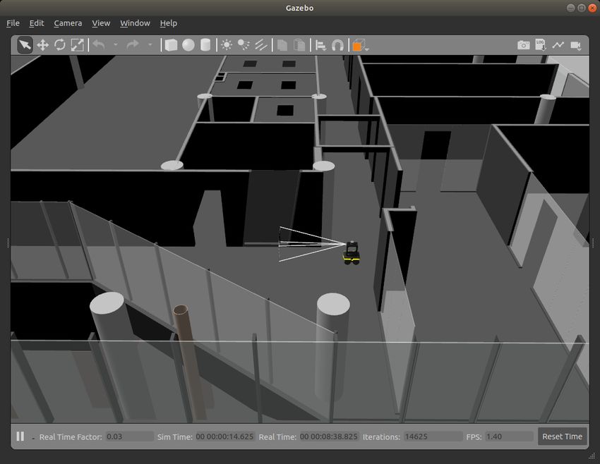
of our work.
                    II. R ELATED W ORK
   Conventional methods of indoor path planning often refer
to optimal path as the shortest path calculated by various
algorithms such as A* and Dijkstra’s [11]. To enhance the
performance of these planers, many studies suggested ways
to leverage BIM/IFC for indoor path planning. Wang et al.
[12] develop a framework for converting the BIM digital           Fig. 1. A directed hypergraph of S = (V, E) where V = {V1 , V2 , ..., Vn }
environment to a cell-based infrastructure to support indoor      is a set of nodes and E = {E1 , E2 , .., Em } is a set of hyperedges. Each
                                                                  node (Vi ) is an IfcSpace containing its relationships and each hyperedge
path planning. In this work, they emphasize on the ”BIM           (Ej ) is an IfcDoor with its attributes extracted by BIRS [24].
voxelization” process rather than the path planning problem.
In another study, a BIM-based path planning strategy is           information in a full navigation stack (3) the field validation
used for equipment travel on construction sites [13]. The         of strategy using BIM/IFC for both global and local path
authors extract the start and end points from BIM and then        planning. In this paper, we cover these gaps by integrating
generate the shortest sequence of rooms for the operator,         Building Information Robotic System (BIRS) into a naviga-
but does not support robot path planning. Ibrahim et al.          tion system in ROS in order to determine the optimal path
[14] propose a path planning strategy based on BIM for            and then navigate autonomously.
an Unmanned Aerial Vehicle (UAV) on construction sites
which uses a camera for data capturing. They use BIM                 III. TOPOLOGICAL BUILDING MAPS CREATED FROM
geometries to define a path for outdoor environments but                               BIM/IFC
do not address indoor semantic robot path planning. In
this direction, Follini et al. [15] utilize BIM geometries for       IFC data schema provides construction stakeholders with
path planning of an UGV supporting construction logistics         semantic information of buildings containing attributes and
application. Their proposed system uses a human-assisted          relationships between different entities [22]. This information
approach in a controlled environment and is yet to thoroughly     can be extracted in graph database [23]. However, the use
leverage BIM/IFC semantics in a construction site. In [16],       of that information for reasoning is complex since the IFC
the optimal route for a data collection mission using an UAV      files encompass large amounts of data. In order to cope with
is proposed. They utilize 4D BIM to identify which building       this, we first identify the required data for robot navigation
spaces are expected to change during the construction phase       on construction sites, then, we extract and store the data in
(implemented in a simulated environment) so that the flight       an XML database. The conceptual semantic relation between
path navigate through those areas and collect data.               BIM/IFC and robot navigation is covered in a previous paper
   Delbrügger et al. [17] developed a framework supporting       on BIRS [24]. We extend the hypergraphs of Palacz et al. [11]
humans and autonomous robots navigation which mostly              with the semantic and geometric information of IFC files. All
uses building geometries in a simulated environment. In [18],     the semantic information required to the global and local
the indoor localization of an UAV is assessed using AptilTags     planers retrieved from IFC is in the form of a topological
with their known location in a BIM-generated map. They            map.
present this work as a proof-of-concept for the use of April-        As IEEE 1873-2015 [25] defines, nodes and edges are the
Tags in indoor environment. However, due to inaccuracy of         components of topological maps and we fill them with the
localization in their work, they improve their previous work      following information:
by using Extended Kalman Filter (EKF) in their localization          •   Nodes contain the rooms information namely: room’s
framework [19]. Another study examined the use of BIM                    name, room’s unique ID, room center, room area, walls’
in robot localization in which the proposed system uses a                unique IDs, wall material, last scan date, construction
hierarchical reasoning for path planning [20]. BIM was also              activity (hazard for the robot)
demonstrated to be powerful for the identification of different      •   Edges contain the doors information namely: door’s
paths from which a hierarchical refinement process can find              unique ID, door’s location, doors opening direction
the shortest path [21]. That work provides only high-level           In the hypergraph, one node is created per IfcSpace and
path (rooms sequence) with respect to BIM geometries and          for each IfcSpace, the bounding IfcWall and IfcCurtainWall
the integration with ROS is not studied. An approach using        elements are identified. With the above-mentioned informa-
hypergraphs generated from IFC files was also developed in        tion, a graph is generated as illustrated in fig. 1. Then,
which a modified A* algorithm is able to detect the optimal       the edges need to be attributed with the cost (weight) of
path among nodes in the graph [11].                               passing over each (from a room to another). In this direction,
   In these inspiring works three aspects of the BIM potential    W = (WV , WE ) is a pair of weights where WV and WE
for indoor robot path planning are yet to be thoroughly           are the node and hyperedge weights respectively. WVi is the
studied: (1) considering the full potential of the BIM/IFC        i node total weight obtained from:
semantic rather than only the geometry (2) integrating the
high-level (rooms sequence) with the low-level sensor-based                          WV = wm + wa + ws + wh                             (1)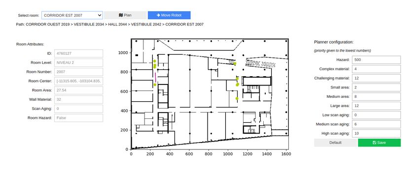
where wm depends on the walls material, wa , on the room           Inputs:
area, ws , on the room scan-age, and wh , on the room hazards.       layout_graph : hypergraph
WEj is the j hyperedge weight obtained from:                         tail_room, head_room : node
                                                                     door : hyperedge
                          WE = wd                           (2)      path_weight : hyperedge_total_weight
where wd depends on the door opening direction. For passing        Outputs:
from one node to the other, there might be several paths the         semantic_path : list
robot can use. The overall weight of a path (from start to           x_y_path : list
                       X n        Xm                                 hyperedge_total_weight : number
                 W =       WV i +    W Ej                (3)
                        i=1         j=1                            Fig. 2.   Data structure for IFC-based semantic optimal path planner
One challenge for the robot is to be able to detect obstacles.     algorithm
To help the robot predict and avoid potential failures, the
                                                                           IV. F INDING T HE O PTIMAL I NDOOR PATH
material properties of the walls are extracted through Ifc-
Material and its super-type IfcProduct. The weight of each            As Gallo et al. [26] define, directed hypergraphs are
curtain wall, i.e. walls that are invisible by design, in each     divided into two categories according to their hyperedges
node is wm = 12, while all others are wm = 4 since they            namely: forward hypergraph (F-hypergraph) and backward
can be easily detected. The time required to go through a          hypergraph (B-hypergraph). The former is a directed hyper-
transition node is also taken into account, i.e. bigger rooms      graph in which one node diverges to several nodes and the
take more time for the robot to cross. Accordingly, the weight     latter is the one in which several nodes converge to one node.
for the rooms less than 50m2 , between 50m2 to 100m2 and           As an example of applications, F-hypergraphs are employed
more than 100m2 are wa = 2, wa = 8 and wa = 12                     for time analysis on transportation networks [27]. Also, B-
respectively. Since one of the core purpose of deploying           hypergraphs are used to perform deductive analysis to find
robots on construction sites is to collect data, the scanning      the optimal path in a hypergraph. The combination of B-
age of all rooms is incorporated. The progress monitoring          hypergraph and F-hypergraph is a BF-hypergraph having
needs up-to-date data and when the robot is collecting data        both divergent and convergent nodes [26]. In topological
it can optimise its path to visit more rooms and collect more      building layouts, we deal with BF-hypergraphs since we
data. The scanning periods are selected according to industry      have spaces which connect several spaces to other spaces (an
needs, therefore, we assign ws = 10, ws = 6, ws = 0                example of such nodes is corridors). In addition, we intend to
for the scanning period of less than 1 week, between 1             find the optimal path (a ”deductive database analysis” from
week and 2 weeks, and more than 2 weeks respectively.              several possible paths) based on several criteria which are
Since the construction projects evolve constantly, the safety      represented as weights in the hypergraph, therefore, we use
aspects of robot navigation are essential. In this direction,      the ”Shortest Sum B-Tree” algorithm which finds a hypertree
the data collection for the spaces with ongoing construction       (subhypergraph) of the nodes as explained in [26]. We also
activities should be postponed to a safer moment for the           use additive weighting function to calculate the cumulative
robot to navigate those rooms. If the hazardous space is           weight of each possible route and then we choose the lighter
one of the transition nodes, an alternative route needs to be      route which is the optimal path for the robot.
automatically planned so we assign wh = 500 for the weight            In order to create the hypergraph, we first retrieve all
of passing through such spaces. In this case, another path will    the relevant IFC information. The process is done with a
be selected by the algorithm if there is any. If there is not an   Dynamo script (a visual programming tool) to extract the
alternative safe path for the robot, the algorithms provides       IFC parameters in order to export the IFC information in a
a warning for high-weight paths so that the supervisor of          XML database. A Python script is developed to parse the
the robotic deployment is warned. The hypergraph repre-            XML data in order to translate meaningful data to ROS
senting building topological map enables the robotic system        (for example, the rooms center coordinates are retrieved as
to find the optimal path by running an algorithm. In this          strings so they need to be parsed to be integrated with the
paper, we use directed hypergraph (with directed hyperedges)       robotic system). With an hypergraph of the whole building,
allowing us to assign cost for door opening directions.            the user defines the start and end nodes (rooms), and let the
IfcDoor as a sub-class of IfcBuildingElement provides the          algorithm find the optimal path. Since we are implementing
center coordinates of the doors creating hyperedges (with          BF-hypergraph, each pair of nodes is connected with two
their coordinates) in the hypergraph. IfcDoor also stores          directed hyperedges together, thereby making a comprehen-
the opening direction through y-axis of ObjectPlacement            sive B-hypergraph within the BF-hypergraph. This practice
parameter. For pushing and pulling the door, we assign             allows considering forward and backward direction in a path
wd = 2 and wd = 6 to the hyperedge’s weight respectively.          so that the door opening direction is considered. ”Shortest
This is due to difficulty for pushing and pulling the doors        Sum B-Tree” algorithm provides the possible hyperedges
respectively. Ultimately, the total weight of passing one to       from a start node to other nodes [26]. Then, the retrieved
the other is the sum of nodes weights and edges.                   information is used to create a sub-hypergraph from the
Fig. 3. Semantic Graphical User Interface for the intuitive operation of the robot navigation on construction sites. The controls in the header allow selecting
a destination and generating the path. The panel to the left shows the attributes of the selected room. The center contains a map of the environment, with
the robot’s pose in real time being represented by the purple arrow. The center points of the rooms and doors in the path are represented in the map by
the yellow circles. The right panel allows the user to reconfigure the different weights that are applied to the path generation.
start node to all other nodes representing all the possible
paths. By giving the destination node to the sub-hypergraph,
the possible paths from start to end node are identified and
finally the lowest cumulative weight of the paths is retrieved.
Having a set of nodes and hyperedges from the optimal
path, the building information is extracted to enable semantic
navigation. Each node is represented by the name of the
corresponding space and the center coordinates of that room.
As illustrated in fig. 2, the optimal path outputs a set room
names, their coordinates and a set of door coordinates in the
sequence of node location and hyperedge (door) location.
The room names enable semantic navigation and the 2-D
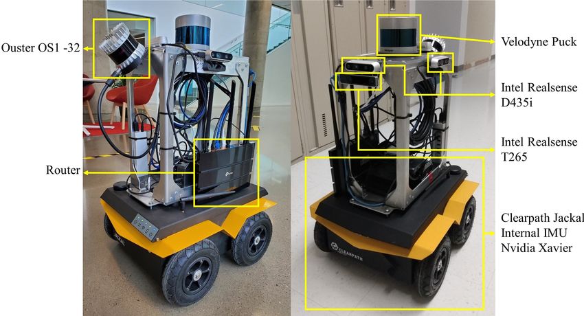
Fig. 4. Mobile robot platform equipped with various sensors
coordinates provides destinations one after the other.
VI. F IELD DEPLOYMENT
V. S EMANTIC G RAPHICAL U SER I NTERFACE
Our approach was validated from simulation to the field
A Graphical User Interface (GUI) was developed based on with an experimental case study. The goal was to drive a
BIM semantics to allow users to intuitively operate the robot mobile robot through the corridors of one of the buildings at
and configure the path planner. The GUI connects to the the École de technologie supérieure, for which a complete
ROS running in the robot and presents semantic information BIM model was available, and collect data. The semantic
of the building and data from the robot in real time. The path planner was used to generate a set of waypoints from
integrated high-level and low-level navigation system moves the user inputs, then a low level A* path planner aided by a
the robot to the desired destination. The GUI allows the non- collision detection stack navigates the robot.
expert users to work with their domain knowledge, thereby Our robotic platform, shown in fig. 4, is built from a
making robot deployment more intuitive and simpler. Figure four-wheeled unmanned ground vehicle (Clearpath Jackal)
3 illustrates the interface window. The GUI is developed in equipped with wheel encoders, an internal IMU and an
Python notebooks, allowing for easy integration of visual- onboard NVidia Xavier computer. The Jackal is delivered
ization widgets and customization. with ROS nodes for control, odometry estimation (from
The GUI provides the building’s rooms in a drop-down encoders and IMU) as well as diagnostics tools provided
list, from which the user selects a destination and then by ROS.
launch the path planner to find the optimal path. The center The sensing system, which was envisioned for point cloud
area of the GUI shows a map of the building, with the collection in construction sites, contains two LiDARs, five
robot’s pose being updated in real time, along with the paths depth cameras and one tracking camera. The sensors are
objectives. The left panel shows the selected room’s (end positioned in different directions to cover as much as possible
node) attributes. The right panel allows the user to alter of the robot’s surroundings. While all sensors collect and
the weights of each parameters of the path planner. After record data of the environment, most of them are also used by
changing and saving the new weights, the user can generate the navigation stack for localization and collision avoidance.
the path again and see the results on the map. Finally, the Below we present a detailed description of each sensor or
user can click on the Move Robot button to trigger the robot group of sensors:
to start moving. • Front facing cameras: One Intel Realsense D435idepth camera and one Intel Realsense T265 tracking
camera are mounted in front of the robot. The T265
software estimates the camera’s pose and integrates data
from the base odometry (wheel encoders and IMU),
providing accurate odometry that is fed to the localiza-
tion algorithm. The D435i provides depth images that
are used to detect obstacles immediately in front of the
robot, triggering an emergency stop;
• Velodyne Puck 32MR LiDAR: Mounted horizontally
on top of the robot, it captures laser scan data from
all around the robot. This information is used by the
localization algorithm to estimate the robot’s global
position on the building map;
• Depth cameras: Three Intel Realsense D435i depth
cameras are mounted pointing to the top and left and
right sides of the robot. Their purpose is to collect RGB
images and depth images from the walls around the
robot and from the ceiling;
• Ouster OS1 LiDAR: The last sensor, an Ouster OS1
LiDAR is mounted in the back of the robot, inclined by
an angle of 45 degrees in order to capture point clouds
of the ceiling. Since this sensor has a large 90° field of
view, it is also able to cover the walls and part of the Fig. 5. System Overview: A high level planner that process BIM/IFC
back of the robot. information and user inputs is integrated to a low level navigation stack in
a cascade design. The low-level module takes care of the localization, local
Figure 5 gives an overview of the system. The robot path planning and collision avoidance tasks, while the high-level planner
pose in the map is obtained through the use of a ROS generates paths based on BIM/IFC semantics.
implementation of the Adaptive Monte Carlo localization
algorithm[28][29]. Before deploying the robot, wall geom-
etry information is extracted from BIM to generate an
occupancy grid of the building. During the robot navigation,
this map, the odometry, and the laser scan data from the hori-
zontally mounted Velodyne LiDAR are fed to the localization
algorithm, which then estimates the robot’s current pose in
that map. When a destination room is selected, the semantic
path planner outputs the preferred path to that room as a
list of waypoints, containing the center points of each room,
door and corridor in the path. An A* path planner[30] then
calculates the shortest path from the robot’s current position
to the next waypoint in the list. Velocity commands are
generated from the A* path and sent to the robot’s internal Fig. 6. View of the simulated environment used to test the BIM/IFC optimal
controller to drive it though that path. path planning approach. The building 3D model was built with geometry
information extracted from the BIM. The robot model simulates the sensors
The simulation was performed using the Gazebo Simu- and possesses the same characteristics as the real robot.
lator. The building information is exported to create a 3D
model, a digital twin. Clearpath, Gazebo and the ROS com- In our case study, the robot starts in a corridor (CORRI-
munity provide all the required software packages required DOR OUEST) on the west side of the building and must
to generate an accurate simulation of our robotic platform. reach an open area (CORRIDIR EST) on the eastern part of
Figure 6 shows the simulated robot and its environment with the building. Figure 7 shows the building map, and the path
different wall textures and transparency. in red line generated by applying the A* algorithm from start
to end. This is the shortest possible path between the two
VII. R ESULTS points, taking into consideration only the building geometry
The experiment had two main objectives: and a small safety collision radius around the robot. When
1) Test the effectiveness of the semantic path planner the Semantic Path Planner is applied to the same scenario,
in generating the optimal path to reach the destina- a similar result is obtained as expected, represented by the
tion, given the building information obtained from blue path in fig. 7. Since there are no doors, undesirable
BIM/IFC. materials or hazards in the path, the algorithm outputs a list
2) Test how changes in the building information affect the of rooms that must be visited by the robot that represent
final path that is generated. the shortest distance from start to end. The semantic pathplanner provided the order of rooms’ names from the start
to the end as it is show in the GUI in fig. 3. Therefore,
the user operating the robot can intuitively track the path
from the data collected. In this direction, the as-built data
can be directly compared to the as-planned since the path is
recorded semantically. Also, the waypoints of rooms’ center
coordinates and doors’ center coordinates are provided by the
semantic path planner. If there is a door made of materials
invisible to sensors (such as glass), the complementary door
coordinates helps for safer, smarter, precise data collection.
Following this, the A* algorithm finds the shortest path
between the waypoints.
In a second run, the building information was altered
to include a construction operation carried out in the area
highlighted with a dashed box in fig. 7 (not visible in the
GUI). Since the construction activity represents a hazard with
a high cost for the Semantic Path Planner, a different path
passing through another corridor is automatically selected, Fig. 7. High-level and low-level paths: A* generates the shortest path
as illustrated by the orange path. Nevertheless, the high possible between start and end, not taking advantage of the BIM/IFC
semantics. Path 1 has the lowest total weight among other alternatives. Path
cost of the shortest path triggered a warning in the system 2 is automatically generated when there is a hazard to the robot in path 1.
indicating a hazard to the user through the semantic GUI.
Therefore, the user can understand the risks associated with generate different paths given different conditions was shown
navigation through an active construction area and decide in a simulated and real life case study.
whether to scan the environment or postpone it to a safer This algorithm can be extended in the future to take into
time. The orange path was automatically generated, although consideration Mechanical, Electrical and Plumbing (MEP)
it is not the shortest path, as the optimal path from the semantics for data collection. Different locations can be
default parameters mentioned in section IV. This path passes added based on the kind of information needed at a specific
along a large curtain wall invisible to the robot’s sensors. time of construction through the GUI in order to provide the
The additional semantic information provided by the BIRS robot more destinations to collect data. Therefore, the high-
is given to the robot as well as the BIM occupancy grid level path planning algorithm would provide a more efficient
so it contributes to collision avoidance with the wall. The route for data collection as well as semantic navigation. Also,
GUI provides the user with the scan aging of the rooms so this paper provided semantic navigation of mobile robot on
the user can decide which rooms to select as the destination construction sites, therefore, a user study will be conducted
for data collection. This allows the users to run multiple in order to assess the usability of the semantic navigation
data collection mission with the robot which increases the approach.
efficiency of robot deployment on construction sites. As
illustrated in fig. 7, the integrated BIM-ROS information ACKNOWLEDGMENT
provides a cascade navigation system on construction sites
enabling autonomous and accurate data collection of the The authors are grateful to the Natural Sciences and
spaces scanned. Engineering Research Council of Canada for the financial
support through its CRD program 543867-2019, to Mitacs
for the support of this field study as well as Pomerleau;
VIII. C ONCLUSION
the industrial partner of the ÉTS Industrial Chair on the
This paper presented a semantic path planner that uses Integration of Digital Technology in Construction.
building information from IFC data schema to generate
optimal paths for safe and efficient navigation of autonomous R EFERENCES
robots on job sites during the construction phase. We used [1] E. P. Karan and J. Irizarry, “Extending bim interoperability to pre-
the BIRS for extracting building information from IFC rep- construction operations using geospatial analyses and semantic web
resented in a hypergraph structure. Path planning algorithms services,” Automation in Construction, vol. 53, pp. 1–12, 2015.
[2] J. S. Álvares and D. B. Costa, “Construction progress monitoring
can then be used to calculate optimal paths in this graph using unmanned aerial system and 4d bim,” in Proceedings of the
given the building information. Weights are designated to 27th Annual Conference of the International. Grupo para Construção
each connection in the path to represent how different condi- Enxuta (IGLC), Dublin, Irlanda, 2019, pp. 1445–1456.
[3] J. Teizer, “Status quo and open challenges in vision-based sensing and
tions can affect the robot’s navigation and to prioritize paths tracking of temporary resources on infrastructure construction sites,”
with more desired characteristics. The optimal semantic path Advanced Engineering Informatics, vol. 29, no. 2, pp. 225–238, 2015.
is then integrated with low-level navigation system and A* [4] B. G. de Soto, I. Agustı́-Juan, J. Hunhevicz, S. Joss, K. Graser,
G. Habert, and B. T. Adey, “Productivity of digital fabrication in
algorithm is used to calculate the shortest path within the construction: Cost and time analysis of a robotically built wall,”
optimal path. The effectiveness of the path planning to Automation in Construction, vol. 92, pp. 297–311, 2018.[5] Pomerleau. Pomerleau: First company in the world [24] S. Karimi, I. Iordanova, and D. St-Onge, “An ontology-based approach
to welcome spot, the robot on its jobsites! to data exchanges for robot navigation on construction sites,” submit-
[Online]. Available: https://pomerleau.ca/en/news/107/ ted.
pomerleau-first-company-in-the-world-to-welcome-spot-the-robot-on-its-jobsites
[25] “Ieee standard for robot map data representation for navigation,”
[6] P. Kim, J. Chen, J. Kim, and Y. K. Cho, “Slam-driven intelligent 1873-2015 IEEE Standard for Robot Map Data Representation for
autonomous mobile robot navigation for construction applications,” Navigation, pp. 1–54, 2015.
in Workshop of the European Group for Intelligent Computing in [26] G. Gallo, G. Longo, S. Pallottino, and S. Nguyen, “Directed hyper-
Engineering. Springer, 2018, pp. 254–269. graphs and applications,” Discrete applied mathematics, vol. 42, no.
[7] K. Asadi, P. Chen, K. Han, T. Wu, and E. Lobaton, “Lnsnet: 2-3, pp. 177–201, 1993.
Lightweight navigable space segmentation for autonomous robots on [27] A. A. Prakash and K. K. Srinivasan, “Finding the most reliable
construction sites,” Data, vol. 4, no. 1, p. 40, 2019. strategy on stochastic and time-dependent transportation networks:
[8] I. Kostavelis and A. Gasteratos, “Semantic maps from multiple visual A hypergraph based formulation,” Networks and Spatial Economics,
cues,” Expert Systems with Applications, vol. 68, pp. 45–57, 2017. vol. 17, no. 3, pp. 809–840, 2017.
[9] S. Karimi and I. Iordanova, “Integration of bim and gis for construction [28] “amcl,” http://wiki.ros.org/amcl, accessed: 2021-02-24.
automation, a systematic literature review (slr) combining bibliomet- [29] S. Thrun, “Probabilistic robotics,” Communications of the ACM,
ric and qualitative analysis,” Archives of Computational Methods in vol. 45, no. 3, pp. 52–57, 2002.
Engineering, pp. 1–22, 2021. [30] P. E. Hart, N. J. Nilsson, and B. Raphael, “A formal basis for the
[10] J. Crespo, J. C. Castillo, O. M. Mozos, and R. Barber, “Semantic heuristic determination of minimum cost paths,” IEEE transactions on
information for robot navigation: A survey,” Applied Sciences, vol. 10, Systems Science and Cybernetics, vol. 4, no. 2, pp. 100–107, 1968.
no. 2, p. 497, 2020.
[11] W. Palacz, G. Ślusarczyk, B. Strug, and E. Grabska, “Indoor robot
navigation using graph models based on bim/ifc,” in International
Conference on Artificial Intelligence and Soft Computing. Springer,
2019, pp. 654–665.
[12] Q. Wang, W. Zuo, Z. Guo, Q. Li, T. Mei, and S. Qiao, “Bim
voxelization method supporting cell-based creation of a path-planning
environment,” Journal of Construction Engineering and Management,
vol. 146, no. 7, p. 04020080, 2020.
[13] S. Song and E. Marks, “Construction site path planning optimization
through bim,” in Computing in Civil Engineering 2019: Visualization,
Information Modeling, and Simulation. American Society of Civil
Engineers Reston, VA, 2019, pp. 369–376.
[14] A. Ibrahim, D. Roberts, M. Golparvar-Fard, and T. Bretl, “An interac-
tive model-driven path planning and data capture system for camera-
equipped aerial robots on construction sites,” in Computing in Civil
Engineering 2017, 2017, pp. 117–124.
[15] C. Follini, M. Terzer, C. Marcher, A. Giusti, and D. T. Matt, “Com-
bining the robot operating system with building information modeling
for robotic applications in construction logistics,” in International
Conference on Robotics in Alpe-Adria Danube Region. Springer,
2020, pp. 245–253.
[16] A. Ibrahim and M. Golparvar-Fard, “4d bim based optimal flight plan-
ning for construction monitoring applications using camera-equipped
uavs,” in Computing in Civil Engineering 2019: Data, Sensing, and
Analytics. American Society of Civil Engineers Reston, VA, 2019,
pp. 217–224.
[17] T. Delbrügger, L. T. Lenz, D. Losch, and J. Roßmann, “A navigation
framework for digital twins of factories based on building information
modeling,” in 2017 22nd IEEE International Conference on Emerging
Technologies and Factory Automation (ETFA). IEEE, 2017, pp. 1–4.
[18] M. Nahangi, A. Heins, B. McCabe, and A. Schoellig, “Automated
localization of uavs in gps-denied indoor construction environments
using fiducial markers,” in ISARC. Proceedings of the International
Symposium on Automation and Robotics in Construction, vol. 35.
IAARC Publications, 2018, pp. 1–7.
[19] N. Kayhani, A. Heins, W. Zhao, M. Nahangi, B. McCabe, and A. P.
Schoelligb, “Improved tag-based indoor localization of uavs using
extended kalman filter,” in Proceedings of the ISARC. International
Symposium on Automation and Robotics in Construction, Banff, AB,
Canada, 2019, pp. 21–24.
[20] B. Siemiatkowska, B. Harasymowicz-Boggio, M. Przybylski,
M. Różańska-Walczuk, M. Wiśniowski, and M. Kowalski, “Bim
based indoor navigation system of hermes mobile robot,” in Romansy
19–Robot Design, Dynamics and Control. Springer, 2013, pp.
375–382.
[21] A. Hamieh, A. B. Makhlouf, B. Louhichi, and D. Deneux, “A bim-
based method to plan indoor paths,” Automation in Construction, vol.
113, p. 103120, 2020.
[22] A. Ismail, B. Strug, and G. Ślusarczyk, “Building knowledge extrac-
tion from bim/ifc data for analysis in graph databases,” in International
Conference on Artificial Intelligence and Soft Computing. Springer,
2018, pp. 652–664.
[23] B. Strug and G. Ślusarczyk, “Reasoning about accessibility for dis-
abled using building graph models based on bim/ifc,” Visualization in
Engineering, vol. 5, no. 1, pp. 1–12, 2017.You can also read