70 Series 70 Flexible. Tactile and reliable - EAO
←
→
Page content transcription
If your browser does not render page correctly, please read the page content below
Series   70

Series 70
Flexible. Tactile and reliable.
https://eao.com/70
70 Information about the Series
Key advantages                              Lens Material

§   Full-face illumination                  §   Plastic
§   Excellent tactile feedback
§   Almost limitless design possibilities   Markings
§   Easy-to-clean, UV-resistant films
§   PCB mount switches                      §   Printed insert film legends

Typical application areas                   Conformities

§   Machinery                               §   CE
§   Public transportation                   §   2011/65/EU (RoHS)
§   Heavy duty and special vehicles
§   Marine
§   Telecommunications
§   Medical technology
§   Energy supply
§   Automation
§   Building infrastructure
§   Food and beverage industry

Functions

§   Pushbutton
§   Illuminated pushbutton
§   Indicator

Design

§   Flush

IP front protection

§   IP40

Raitings

§   42 VAC (100 mA)

Terminal

§   PCB

800                                                                          eao.com § 03/2020
Index 70
PCB
Switching element without illumination 802
01
Switching element with illumination 804
Indicator element 806 02
Components 808
Accessories 810 03
Technical data 811
Application Guidelines 813
04
09
14
17
18
19
22
31
41
45
51
56
57
61
70
71
82
84
92
96
03/2020 § eao.com 801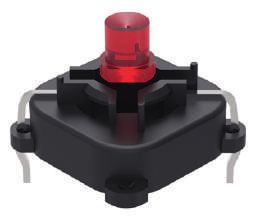
70 PCB
Switching element without illumination
01
9 Equipment consisting of (schematic overview)
02 3.5 3.5 1
Spacer cap Page 810
Ø 1.6
03
Ø 7.9
12.5
A
Switching element
04 4.3 1.5 5
12 x 12 Each Part Number listed below includes all the
black components shown in the 3D-drawing.
09 1.2 3
3.8 x 3.8
To obtain a complete unit, please select the red
Product can differ from the current configuration.
components from the pages shown.
14 B
3
17
4.5 3.6
1
3.8 x 3.8
1.8
.8
18
16
3x3
2 4
12.5
C
19
1 3
4 5.08
22 7.5 12.8 x 12.8
Dimensions [mm]
A = For Part No. 70-100.0
31 B = For Part No. 70-101.0
C = For Part No. 70-201.0
41 General information
• Contact normally open
• Dimensions with fitted spacing cap see details
45 Spacing cap
51
56 Switching element
Com-
Wiring ponent
57 Product attributes Contact material Switching action Terminal Part No. diagram Layout
Operation without spacing cap Silver Momentary PCB terminal 70-100.0 331 80
61
70 Switching element
Com-
Wiring ponent
71 Product attributes Contact material Switching action Terminal Part No. diagram Layout
Operation with spacing cap Silver Momentary PCB terminal 70-101.0 331 80
82
84 Switching element
Com-
92 Wiring ponent
Product attributes Contact material Switching action Terminal Part No. diagram Layout
Operation with spacing cap Gold Momentary PCB terminal 70-201.0 332 79
96
802 eao.com § 03/2020
PCB 70
Wiring diagrams
01
3 4 3 4
02
03
1 2 1 2
04
Wiring diagram 331 Wiring diagram 332
09
Component layouts
14
A C A C
17
B B
Ø2.0 (2x) 18
D
C C 1 2
19
5.08
C C 1 2
C C 3 4 B
9.00
5.08
C B C 3 4
12.70
Ø1.3 (4x)
Ø1.3 (4x)
22
D
12.70
E
Component layout 80
31
Component layout 79
Dimensions [mm] Dimensions [mm]
A = Switching element without illumination A = Switching element without illumination with 41
B = Drilling plan (component side) B = Drilling plan (component side)
C = Occupancy plan (component side) C = Occupancy plan (component side)
D = Hole for switching element D = Hole for centering pins non-metallic
E = Hole for switching element 45
51
56
57
61
70
71
82
84
92
96
03/2020 § eao.com 803
70 PCB
Switching element with illumination
01
Ø8 Equipment consisting of (schematic overview)
02
5.7
4
9.3
Lens Page 808
03 12.5 1
3.6
Single-LED
04 1 2
10.16
5.08
12.5
3 4
16
Switching element
09
.8
Product can differ from the current configuration.
Dimensions [mm] Each Part Number listed below includes all the
14 black components shown in the 3D-drawing.
To obtain a complete unit, please select the red
General information components from the pages shown.
17 • The customer has to decide what series resistor
shall be used to the LED
• Luminosity and wave length variations caused
18 by LED manufacturing processes may cause
slight differences regarding the illumination. The
customer has to decide what resistor shall be
19 used to the LED
• Dimensions with fitted spacing cap see details
Spacing cap
22 • Contact normally open
31
41 Switching element
Com-
Forward Contact ma- Lumi. Inten- Switching Illumination Wiring ponent
45 voltage terial sity Dom. Wavelength action Terminal colour Part No. diagram Layout
2.0 VDC @ 20 Gold 160 mcd 625 nm Momentary PCB ter- Red 70-220.2S 333 82
mA minal
51 2.9 VDC @ 20 Gold 600 mcd 580 nm Momentary PCB ter- Yellow 70-220.4S 333 82
mA minal
3.2 VDC @ 20 Gold 650 mcd 525 nm Momentary PCB ter- Green 70-220.5S 333 82
56 mA minal
3.0 VDC @ 20 Gold 250 mcd 467 nm Momentary PCB ter- Blue 70-220.6S 333 82
mA minal
57 3.2 VDC @ 20
mA
Gold 500 mcd x: 0.31 / y: 0.32 nm Momentary PCB ter-
minal
White 70-220.9S 333 82
61
Switching element
70
Com-
Wiring ponent
71 Contact material
Gold
Switching action
Momentary
Terminal
PCB terminal
Part No.
92-851.342
diagram
332
Layout
82
82
84
92
96
804 eao.com § 03/2020
PCB 70
Wiring diagrams
01
3 4 3 4 +
02
03
1 2 1 2 –
04
Wiring diagram 332 Wiring diagram 333
09
Component layouts
14
A C
17
B
18
Ø1.3 (4x)
D 19
B K
C 2
C 1
10.16
C 4
C B 3
A 22
10.16 Ø1.0 (2x)
12.70 E
31
Component layout 82
41
Dimensions [mm]
A = Switching element with illumination
B = Single LED
C = Drilling plan (component side)
45
D = Hole for switching element, Pad max. Ø 2.5 mm
E = Hole for LED
51
56
57
61
70
71
82
84
92
96
03/2020 § eao.com 805
70 PCB
      Indicator element
01
                                                                                                                                 Equipment consisting of (schematic overview)
02

                                                                              1.6

                                                                                                             5.7
                                                                                                     4
                                                                                                                                                Lens                     Page 808
03                                                                                    .8
                                                                                    16

                                                                                                           0.
                                                                                                              8
                                                                                                             x
                                                                                                               0.
                                                                                                    6.35

                                                                                                                  8
                                                                                                                                                Single-LED
04
                                                                                             12.5
                                                                                                                                                Illumination element
09
     Product can differ from the current configuration.         Dimensions [mm]
                                                                                                                                 Each Part Number listed below includes all the
                                                                                                                                 black components shown in the 3D-drawing.
14   General information
                                                                                                                                 To obtain a complete unit, please select the red
     • The customer has to decide what series resistor                                                                           components from the pages shown.
       shall be used to the LED
17
     • Contact normally open

     • Luminosity and wave length variations caused
18     by LED manufacturing processes may cause
       slight differences regarding the illumination. The
       customer has to decide what resistor shall be
       used to the LED
19

22
                     Indicator element
31                                                                                                                                                                        Com-
                                                                                                                                                              Wiring      ponent
      Illumination colour       Forward voltage             Lumi. Intensity                Dom. Wavelength            Terminal          Part No.              diagram     Layout

41    Red                       2.0 VDC @ 20 mA             160 mcd                        625 nm                     PCB terminal      70-820.2S             330         81
      Green                     3.2 VDC @ 20 mA             650 mcd                        525 nm                     PCB terminal      70-820.5S             330         81

45
                     Indicator element
51
                                                                                                                                                                          Com-
                                                                                                                                                               Wiring     ponent
56    Terminal
      PCB terminal
                                                                                                                                        Part No.
                                                                                                                                        92-800.042
                                                                                                                                                               diagram
                                                                                                                                                               330
                                                                                                                                                                          Layout
                                                                                                                                                                          79

57    Wiring diagrams

61               +

70
                 –
71

82    Wiring diagram 330

84

92

96

     806                                                                                                                                                        eao.com § 03/2020
PCB 70
Component layouts
01
A C A C
02
B B
03
Ø1.0 (2x)
C C 1 2
D 04
5.08
C C 3 4
B K
10.16
C
6.35
Ø1.3 (4x) B
C A 09
12.70
D
6.35 Ø1.0 (2x)
14
10.16 E
Component layout 79 Component layout 81 17
Dimensions [mm] Dimensions [mm]
A = Switching element without illumination A = Illumination element
B = Drilling plan (component side) B = Single LED 18
C = Occupancy plan (component side) C = Drilling plan (component side)
D = Hole for switching element D = Hole for centering pins non-metallic
E = Hole for LED
19
22
31
41
45
51
56
57
61
Flexible. Tactile and reliable. 70
EAO Series 70.
71
Proven in customer-specific membrane applications – thanks to almost limitless design possibilities.
. Long-standing HMI System competence
. Homogeneous illumination 82
. Excellent tactile feedback
. Almost limitless design possibilities
. Easy-to-clean, UV-resistant films 84
92
www.eao.com/70
96
03/2020 § eao.com 807
70 Components
01

02                          Lens plastic square
      Lens material                   Lens colour    Lens optics       Lens shape          Lens illumination          Dimensions            Part No.
03    Plastic                         White          translucent       flush                illuminative               19.05 mm x 19.05 mm   70-920.9
                                      Red            translucent       flush                illuminative               15,4 mm x 15,4 mm     70-921.2
                                      Orange         translucent       flush                illuminative               15,4 mm x 15,4 mm     70-921.3
04                                    Yellow         translucent       flush                illuminative               15,4 mm x 15,4 mm     70-921.4
                                      Green          translucent       flush                illuminative               15,4 mm x 15,4 mm     70-921.5
                                      Blue           translucent       flush                illuminative               15,4 mm x 15,4 mm     70-921.6
09                                    White          translucent       flush                illuminative               15,4 mm x 15,4 mm     70-921.9
                                      Red            translucent       flush                illuminative               12,4 mm x 12,4 mm     70-922.2

14                                    Orange         translucent       flush                illuminative               12,4 mm x 12,4 mm     70-922.3
                                      Yellow         translucent       flush                illuminative               12,4 mm x 12,4 mm     70-922.4
                                      Green          translucent       flush                illuminative               12,4 mm x 12,4 mm     70-922.5
17                                    Blue           translucent       flush                illuminative               12,4 mm x 12,4 mm     70-922.6
                                      White          translucent       flush                illuminative               12,4 mm x 12,4 mm     70-922.9

18
                                  1

19
                     13.2
                            3.2

               A                      R
22           12.4 x 12.4    R1.5
             15.4 x 15.4    R2.9
           19.05 x 19.05    R2.9                     A
31                Ø12.4
                  Ø15.4
                               –
                               –

     Dimensions [mm]
41   A = Front dimension

45

51                          Lens round
      Lens material                    Lens colour       Lens optics          Lens shape          Lens illumination          Dimensions     Part No.
      Plastic                          Red               translucent          flush                illuminative               Ø 15,4 mm      70-911.2
56                                     Orange            translucent          flush                illuminative               Ø 15,4 mm      70-911.3
                                       Yellow            translucent          flush                illuminative               Ø 15,4 mm      70-911.4

57                                     Green             translucent          flush                illuminative               Ø 15,4 mm      70-911.5
                                       White             translucent          flush                illuminative               Ø 15,4 mm      70-911.9
                                       Red               translucent          flush                illuminative               Ø 12,4 mm      70-912.2
61                                     Orange            translucent          flush                illuminative               Ø 12,4 mm      70-912.3
                                       Yellow            translucent          flush                illuminative               Ø 12,4 mm      70-912.4
                                       Green             translucent          flush                illuminative               Ø 12,4 mm      70-912.5
70                                     White             translucent          flush                illuminative               Ø 12,4 mm      70-912.9

71
                                  1
                     13.2
                            3.2

82
               A                      R

84           12.4 x 12.4
             15.4 x 15.4
                            R1.5
                            R2.9
           19.05 x 19.05    R2.9                     A
                  Ø12.4        –
92                Ø15.4        –

     Dimensions [mm]
     A = Front dimension
96

     808                                                                                                                                    eao.com § 03/2020
Components 70
01
02
Single-LED, T1 3/4 MG
Wiring
Illumination colour Lumi. Intensity Dom. Wavelength Forward voltage Part No. diagram 03
Red 160 mcd 625 nm 2.0 VDC @ 20 mA 10-2601.3172S 70
Amber 165 mcd 605 nm 2.0 VDC @ 20 mA 10-2601.3173S 70
Yellow 600 mcd 580 nm 2.9 VDC @ 20 mA 10-2603.3174S 70
04
Green 650 mcd 525 nm 3.2 VDC @ 20 mA 10-2603.3175S 70
Blue 250 mcd 467 nm 3.0 VDC @ 20 mA 10-2603.3176S 70
09
White 500 mcd x: 0.31 / y: 0.32 nm 3.2 VDC @ 20 mA 10-2603.3178S 70
Additional information
14
• The customer has to decide what series resistor shall be used to the LED
• Luminosity and wave length variations caused by LED manufacturing processes may cause slight diffe-
rences regarding the illumination. The customer has to decide what resistor shall be used to the LED 17
Wiring diagrams 18
x2+ 19
22
x1-
31
Wiring diagram 70
41
45
51
56
57
61
70
71
82
84
92
96
03/2020 § eao.com 80970 Accessories
Front side
01
02
03 Spacing cap
Product attributes Dimensions Part No.
04 Without recesses for LED 18.9 mm 70-901.0
2 recesses for LED 9 mm 70-910.0
13 mm 70-911.0
09 22.5 mm 70-912.0
14 6 20/20/19.05 min.
2
6.
17
6
18
H=9/13/22.5 16/16/15
19 18 min.
22
31 H=18.9 14
Dimensions [mm]
41
45
51
56
57
61
70
71
82
84
92
96
810 eao.com § 03/2020Technical data 70
Switching element illuminated Part No. 92-851.342
01
Switching system Electrical characteristics 02
Short-travel switching system with two independent contact points Electrical life
and tactile operation. Guarantees reliable switching even of very ≥ 500 000 cycles of operation at 42 VDC, 50 mA, 03
light loads 1 normally open contact as per IEC 60512-5-9c
When attention is paid to the direction of current flow from terminal
3/4 to 1/2 the electrical life can be prolonged.
04
Material
Switching voltage and switching current
09
Material of contact Switching voltage min. 50 mV AC / DC
Gold-plated silver max. 42 V AC / DC
Switching current min. 10 μA AC / DC 14
Switching element max. 100 mA AC / DC
Plastic Power rating max. 2 W
17
Electric strength
Mechanical characteristics 500 VAC, 50 Hz, 1 minute, as per IEC 60512-2-4a 18
Actuating force
With overlay foil 4 N ±1.5 N Ambient conditions 19
Max. actuating force > 50 N, as per DIN 42115
Storage temperature
Actuating travel – 40 °C … + 85 °C 22
Approx. 0.4 mm
Operating temperature
31
Resistance to heat of soldering – 25 °C … + 70 °C
250 °C, 3 s (PCB assembly)
320 °C, 3 s (when using a soldering iron) 41
Approvals
Mechanical lifetime
≥ 5 Mio. operations (switching element without overlay) Conformities
45
≥ 1 Mio. operations (switching element under overlay) CE
2011 / 65 / EC (RoHS)
51
Protection
IP40 (only switching element)
IP65 front side with overlay foil 56
57
Switching element non-illuminated Part No. 70-100.0 and 70-101.0
61
Switching system Mechanical characteristics
70
Short-travel switching system with two independent contact points Actuating force
and tactile operation. Guarantees reliable switching even of very With overlay foil 5 N ± 2 N
light loads 1 normally open contact Max. actuating force > 50 N, as per DIN 42115 71
Actuating travel
82
Material 0.3 mm
Material of contact Mechanical lifetime 84
Silver (Ag) 500 000 operations with overlay
Protection 92
IP65 front side with overlay foil
96
03/2020 § eao.com 81170 Technical data
Electrical characteristics Ambient conditions
01
Electrical life Storage temperature
at 5 VDC, 1 mA 500 000 cycles of operation – 30 °C … + 85 °C
02
Switching voltage and switching current Operating temperature
03 Max. 12 VDC, 50 mA – 20 °C … + 70 °C
Min. 1 VDC, 10 mA
04 Electric strength Approvals
250 VAC for 1 minute
09 Conformities
CE
2011 / 65 / EC (RoHS)
14
17 Switching element non-illuminated Part No. 70-201.0
18 Switching system Electrical characteristics
19 Short-travel switching system with two independent contact points Electrical life
and tactile operation. Guarantees reliable switching even of very ≥ 500 000 cycles of operation at 42 VDC, 50 mA,
light loads 1 normally open contact as per IEC 60512-5-9c
22 When attention is paid to the direction of current flow from terminal
¾ to ½ the electrical life can be prolonged.
Material
31 Switching voltage and switching current
Material of contact Switching voltage min. 50 mV AC / DC
41 Gold-plated silver max. 42 V AC / DC
Switching current min. 10 μA AC / DC
Switching element max. 100 mA AC / DC
45 Plastic Power rating max. 2 W
Electric strength
51 Mechanical characteristics 500 VAC, 50 Hz, 1 minute, as per IEC 60512-2-4a
56 Actuating force
With overlay foil 2.1 N ± 0.2 N Ambient conditions
Max. actuating force > 50 N, as per DIN 42115
57 Storage temperature
Actuating travel – 40 °C … + 85 °C
Approx. 0.5 mm
61 Operating temperature
Resistance to heat of soldering – 25 °C … + 70 °C
70 260 °C, 3 s, as per IEC 60068-2-20
Mechanical lifetime Approvals
71 ≥ 5 Mio. cycles of operation (switching element without overlay)
≥ 1 Mio. cycles of operation (switching element under overlay) Conformities
CE
82 Protection 2011 / 65 / EC (RoHS)
IP40 (only switching element)
84 IP65 front side with overlay foil
92
EAO reserves the right to alter specifications without further notice.
96
812 eao.com § 03/2020Application Guidelines 70
Suppressor circuits
01
When switching inductive loads such as relays, DC motors, and volts in amplitude even when nominal circuit voltages are low (e. g. 02
DC solenoids, it is always important to absorb surges (e. g. with a 12 VDC) see Fig. 2.
diode) to protect the contacts. When these inductive loads are
switched off, a counter emf can severely damage switch contacts The free-wheeling diode should be chosen so that the reverse 03
and greatly shorten lifetime. breakdown voltage is greater than the voltage driving the inductive
load. The DC blocking voltage (VR) of the free-wheeling diode can
Fig. 1 shows an inductive load with a free-wheeling diode connec- be found in the datasheet of a diode. The forward current should
04
ted in parallel. This free-wheeling diode provides a path for the be equal or greater than the maximum current flowing through the
inductor current to flow when the current is interrupted by the load. 09
switch. Without this free-wheeling diode, the voltage across the
coil will be limited only by dielectric breakdown voltages of the To get an efficient protection, the free-wheeling diode must be connected as
circuit or parasitic elements of the coil. This voltage can be kilo- close as possible to the inductive load! 14
17
Counter EMF
Switching with inductive load over load without free-wheeling diode
Fig. 1 Fig. 2 18
Switch ON OFF 19
0
+ Free-wheeling Inductive
22
Several hundred
VDC _ diode load to several di
__
thousend volts e = L dt
31
41
Note for soldering
45
Process parameter for wave soldering
51
Basic specification for wave soldering J-STD 75 W4C.
Maximum temperature on the component side (Temp 2): 120 °C 56
(Temperature must not exceed during the entire processing)
Preheating phase (t1 … t2): 70 … 120 sec 57
Ramp up: typ.+ 1 °C / sec
61
Ramp up to maximum temperature (t2 … t3): not defined
Maximum temperature on the soldering side (Temp 3): 250 °C 70
Maximum time of soldering process (t3 … t4): 3 sec
Ramp down at 170 °C: typ. – 2 °C/sec 71
82
84
92
96
03/2020 § eao.com 81370 Application Guidelines
Temperature curve wave soldering
01
02
03
04
09
14
17 Green curve: Temperature on the component side of the pcb
Red curve: Temperature on the soldering side of the pcb
18 Room temperature: Temp 1
19 Preheating: Temperature process = Temp 1 … Temp 2
Process time = t1 … t2
22 Ramp up to soldering temperature: Process time = t2 … t3
Soldering phase: Temperature process = Temp 3
31 Process time = t3 … t4
41
Iron soldering
Basic specification for iron soldering IEC 60068-2-20
45
Maximum temperature at tip of iron: 320 °C
Maximum soldering time: 3 sec
51
56 Cleaning/Lacquering Storage of components
The switching elements are not sealed. Cleaning up the PCB may To obtain the optimum solderability of the components, the fol-
damage the contacts in the switching elements. For this reason, lowing points should be noted during storage:
57 the following points should be noted: – Do not store components in locations with high temperature
– When soldering make sure that the flux does not pass on the or humidity.
upper side of the PCB. – Do not expose components to corrosive gases.
61 – When cleaning the PCB with detergents ensure that no dust – Avoid direct sunlight for a long period.
or other debris may get inside of the switching elements.
– Ensure that no lacquer penetrates into the interior of the
70
switching element when lacquering the PCB.
71
82
84
92
96
814 eao.com § 03/2020You can also read