Single Input LC Series Resonant Converter Based High Brightness Light Emitting Diode Driver with ZVS
←
→
Page content transcription
If your browser does not render page correctly, please read the page content below
Journal of Power Technologies 101 (1) (2021) 54–61
Single Input LC Series Resonant Converter Based High Brightness
Posted on Authorea 18 Mar 2021 — The copyright holder is the author/funder. All rights reserved. No reuse without permission. — https://doi.org/10.22541/au.161608161.12896809/v1 — This a preprint and has not been peer reviewed. Data may be preliminary.
Light Emitting Diode Driver with ZVS
Ramanjaneya Reddy Udumula1,B
1
SRM University, Andhra Pradesh
B
urreddy89@gmail.com
Abstract nation level of the light bulb, it needs to be regu-
lated precisely. LEDs can be powered with either
This work proposes a high brightness light emitting diode (HB-
linear voltage regulators (LVR) or switched mode reg-
LED) driver circuit based on a full-bridge LC series resonant
ulators (SMPS). Nevertheless, SMPS are more com-
converter with series DC bus for low power applications with a
monly used power supplies owing to compactness and
dimming feature. The proposed configuration consists of full-
high efficiency. In literature, several types of converter
bridge LC series resonant converter with a series DC bus. The
configurations such as buck, boost and buck-boost
idea behind the concept is to supply the light emitting diode
converters are proposed, however when these convert-
(LED) threshold voltage directly from the constant DC bus -
ers used for the for LED lighting systems resulted in
and the control voltage, which is used for current regulation,
a trade-off between size of reactive component and
is supplied through a full-bridge LC resonant converter. Since
efficiency [6]; [7]. Therefore, there is a need for an
the control voltage responsible for current regulation is only
efficient LED driver circuit that can perform the same
processed by the full-bridge series resonant converter, the con-
task with more efficiency and durability by implemen-
duction loss is less even if several LED strings are connected to
tation of latest converter topologies [8]; [9]; [10]; [11].
the same converter. The proposed HB-LED driver is character-
ized by low switching loss, reduced component count, high effi-
High brightness LEDs are currently used by manufac-
ciency, and reduction of output electrolytic capacitor. Further,
turing firms to design lamp units. In order to amplify
double pulse width modulation (DPWM) dimming control is
light intensity, multiple numbers of LEDs are stacked
designed and used to control the average output currents. The
together in series and parallel combination as per the
proposed high brightness light emitting diode (HB-LED) driver
load requirement. The intensity of light and chro-
circuit based on a full-bridge LC series resonant converter is
maticity straight away depend on the forward current
simulated using Orcad/PSpice software. The theoretical anal-
passing through the LED; therefore, it is desirable to
ysis and predictions of the proposed full-bridge series resonant
drive LED load with constant current [12]; [13]; [14];
converter-based HB-LED driver is in close agreement with the
[15]; [16]; [17]; [18]; [19]. The idea is to use two
results obtained.
sources, one to supply threshold voltage directly, the
other source being the full-bridge LC series resonant
Keywords: Light Emitting Diodes, LC resonant con- converter, which regulates the LED current. It results
verter, PWM diming, zero voltage switching (ZVS), in improved efficiency and high reliability [20]; [21].
Centre tapped transformer. Fig. 1 (a) and fig. 1(b) illustrate the LED equivalent
model and concept of the proposed work, respectively.
1 Introduction This concept was executed by using buck, boost, and
buck-boost converters as the current regulator for a
Globally, one fifth of electrical energy goes on lighting.
low power application. However, for high power appli-
Hence the drive for efficient, reliable lighting systems.
cations the use of buck, boost, and buck-boost reg-
In virtue of their superior longevity, compactness, ex-
ulators is limited, since increasing load results in a
cellent light efficacy per watt, eco-friendly nature,
reduction in switching frequency, resulting in bulky re-
and color rendering, light emitting diodes (LEDs)
active components. Further, it is difficult to get zero
are replacing conventional light sources in residential,
voltage switching, and lifespan is limited due to the
streetlights, automotive and decorative lighting appli-
presence of electrolytic capacitors at load terminals.
cations [1]; [2]; [3]; [4]; [5].
The flyback converter can be used for low power ap-
Since the forward current of LED alters the illumi- plications; however, it is not advisable to use this con-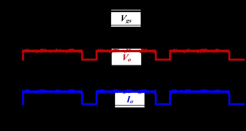
Journal of Power Technologies 101 (1) (2021) 54–61
Posted on Authorea 18 Mar 2021 — The copyright holder is the author/funder. All rights reserved. No reuse without permission. — https://doi.org/10.22541/au.161608161.12896809/v1 — This a preprint and has not been peer reviewed. Data may be preliminary.
Figure 2: Proposed full-bridge LC series resonant con-
Figure 1: (a) Equivalent model of LED; (b) Concept verter
of proposed work
The LC series resonant converter consists of a tank
circuit supplied through a full-bridge inverter. A ca-
verter for output power above 60-70W, as it requires
pacitor is connected at the end of the converter out-
a large transformer which in turn reduces overall ef-
put for filtering purposes. This regulating voltage
ficiency. Dimming control is often needed to control
(Vc) from the LC series resonant converter is added
the illumination level of LED light for the human need
along with the bus voltage and supplied to the LED
to create a comfortable environment. Moreover, dim-
load. The cut-in voltage is supplied directly through
ming operations result in reduced power consumption
bus voltage (V bus ) and the forward regulating cur-
and produce less heat hence increasing LED lifespan
rent is supplied through the full-bridge LC resonant
and optimizing running costs. Therefore, dimming
converter. This regulating current is controlled by
control is essential in LED lighting applications. The
using double pulse width modulation control. The
illumination of LED is directly related to its average
voltage supplied by the full-bridge LC series resonant
current. Therefore, dimming control techniques such
converter is very low compared to the cut-in voltage
as amplitude modulation (AM), pulse width modu-
supplied directly through bus voltage. Hence, switch-
lation (PWM), hybrid AM/PWM technique, integral
ing losses can be greatly reduced on each component,
control and double PWM control are used to regulate
ensuring high power efficiency.
the average output current. These control methods
have their own merits and demerits. This work uses The resonant frequency of the full-bridge LC circuit
the two-source concept of driving LEDs; one is to sup- is decided by the values of the resonant inductor (Lr )
ply cut-in voltage which is directly supplied through and capacitor (C r ) present in the tank circuit. Zero-
the dc bus and other is the regulating voltage sup- voltage-switching (ZVS) and zero-current-switching
plied to the load through a full-bridge series resonant (ZCS) can be decided by resonant frequency (f o ) if
converter as current regulator. The proposed con- the switching frequency (f s ) is higher than resonant
verter has several benefits such as reduced component frequency (f o ) ZVS can be achieved, and the switch-
count, compact size, and reduction of electrolytic ca- ing frequency is lesser than resonant frequency ZCS
pacitors, whereas zero voltage switching results in im- can be achieved. A resonant capacitor (C r ) is added
proved efficiency. The dimming feature was achieved in the circuit to negotiate the impedance effect caused
by using double pulse width modulation control. against the power flow due to parasitic inductance and
supplying voltage with a frequency closer to resonant
frequency to the tank circuit.
2 Circuit Configuration and Op- 2.1 Operating modes
eration Analysis of the circuit is simple, as the circuit is di-
vided into two major parts. The primary part is the
The proposed converter configuration is illustrated
bus voltage (V bus ), which supplies the majority of the
in fig. 2. The bus voltage (V bus ) can be obtained
voltage to the load, satisfying the forward voltage drop
through either an AC grid by using an AC-DC con-
of the LED load. The second part is the full-bridge LC
verter along with a filter or a battery source. A full-
series resonant converter, which supplies the control
bridge LC series resonant converter, operating as a
voltage, regulating the LED output current (I o ). The
current regulator, is placed between the LED load and
resonant converter output (V c ) is connected in series
the dc voltage bus. The power to the LED load is
with the bus voltage as shown in fig. 3.
supplied through a full-bridge LC resonant converter
along with the dc bus, rather than through a resonant The full-bridge LC series resonant converter use con-
converter alone. trolled switches to generate a square wave voltage in-
55 | 61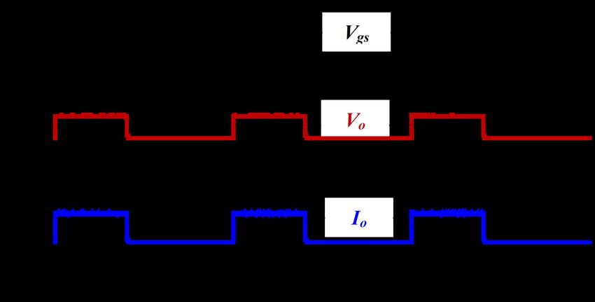
Journal of Power Technologies 101 (1) (2021) 54–61
is as shown in fig. 5. The peak value of the funda-
mental frequencies of the square waves V a and V b
are
Posted on Authorea 18 Mar 2021 — The copyright holder is the author/funder. All rights reserved. No reuse without permission. — https://doi.org/10.22541/au.161608161.12896809/v1 — This a preprint and has not been peer reviewed. Data may be preliminary.
4 · Vbus
Va1 = (1)
π
4 · Vc
Va1 = (2)
π
Figure 3: Proposed circuit topology
The LC resonant tank voltage and currents are given
by
put for the filter for tank current (i L ), formed by the
series combination of resonant inductor (Lr ) and res- (
onant capacitor (C r ). The resonant inductor current +Vbus , 0 < t < δT s
Vr (t) = (3)
(i L ) oscillates and is rectified and filtered to produce −Vbus , δT s < t < T s
dc capacitor output voltage (V c ). The working of the
converter is based on the relation between the reso- Ir (t) = IL (t)sin(t + φ) (4)
nant frequency of the filter and switching frequency
and gives nearly sinusoidal current (i L ) which is os-
cillating in nature and has a frequency almost equal
to switching frequency when the switching frequency
is maintained closer to the resonant frequency of the
filter.
Fig. 4 illustrates the square wave input voltage (V a )
to the filter, the current i L , the switch current i s1
and the input to the centre tapped rectifier V b . The
square wave voltage (V a ) is the inverted waveform of
bus voltage (V bus ). The capacitor voltage (V c ) is the
Figure 5: Equivalent circuit of proposed converter
rectified form of Vb when i L is positive and -V c when
i L is negative. The output voltage of the converter is
assumed to be constant because of the rectifier diode From fig. 5 we have,
configuration.
Vo1 = Vb1 + Vbus (5)
The LED lamp is represented by a forward cut-in volt-
age V F in series with its dynamic resistance r d . The
voltage across the LED lamp can be represented as
VLED = Vr + ILED rd (6)
Here, I LED is the current flowing through the LED lap
which is the average of full wave rectified transformer
secondary current i b .
2 · L1
ILED = Ia = Ib = (7)
π
Figure 4: Voltage and current waveforms for w s >w o The effective load resistance of the resonant converter
can be obtained from eqn. 2 and eqn.7
The proposed full-bridge LC resonant converter is an- Re = m2 Vb1 /IL1 = 8m2 /π 2 RL (8)
alyzed by considering the fundamental components of
the voltages and currents. The AC equivalent circuit where m is the transformer turns ratio (m = Np /Ns ).
56 | 61Journal of Power Technologies 101 (1) (2021) 54–61
To find the relation between V bus and V o , re-
move V bus from fig. 5 as shown in fig. 6.
Posted on Authorea 18 Mar 2021 — The copyright holder is the author/funder. All rights reserved. No reuse without permission. — https://doi.org/10.22541/au.161608161.12896809/v1 — This a preprint and has not been peer reviewed. Data may be preliminary.
Figure 6: Equivalent circuit of proposed converter ex-
cluding V bus
By simplifying eqn. 1 and eqn. 2 the output voltage
can be expressed as
1
V0 = Vbus
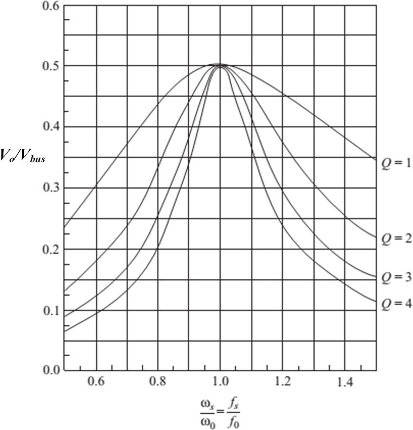
2 (9) Figure 7: Normalized Frequency Response
XL −XC
1+ Re
The values for the components in the series resonant
where, converter are given by the following calculations. The
value of effective load resistance can be expressed as
XL = ωs Lr (10)
8m2
Re = (14)
π 2 RL
1
XC = (11) The quality factor Q can be expressed as
ωs Cr
From the above eqn. 9, eqn. 10 and eqn. 11 it is clear 1
Q= (15)
that the switching frequency has a major impact on 2πfo Re Cr
the output voltage and its sensitivity. Further, the
quality factor of the resonant converter is denoted by By substituting the value of Q in eqn. 13 can be ex-
Q and is expressed as follows pressed as follows
ωS Lr 1
Q= = (12) f02 − [fs2 Rs Cr (Vbus /V0 ) − 1]f03 − (2fs2 )f02 + f04 = 0
Re ωs Re Cr
(16)
By substituting eqn. 10, eqn. 11 and eqn. 12 into By simplifying the 4th order equation, we can obtain
eqn. 9 the gain (V o /V bus ) can be expressed as follows the value of the resonant frequency (f ) and by sub-
o
stituting this value in eqn. 15 for an assumed resonant
V0 1 capacitor value such as C r =0.1μF we can obtain the
= 2
(13) value of the quality factor, which is useful in finding
Vbus h i
1 + Q2 ωω0 − ωω0 QRe
(Lr ) asLr = 2πf (17)Where Q is the quality factor of
o
the converter, Re is the effective load resistance, f o
is the resonant frequency and f s is the switching fre-
The gain (V o /V bus ) versus normalized frequency
quency.
(ωs /ωo ) is plotted with Q as the parameter is illus-
trated in fig. 7. Since i Lr has more of a sinusoidal 2.3 Dimming Control
quantity for the above resonance, the curves are more
accurate in these frequencies. Dimming control is often needed to control the illumi-
nation level of LED light for the human need to create
2.2 Design of Resonant Converter a comfortable environment. Moreover, since dimming
57 | 61Journal of Power Technologies 101 (1) (2021) 54–61
Table 1: Parameters used in simulation of proposed
converter
Parameter Rating
Posted on Authorea 18 Mar 2021 — The copyright holder is the author/funder. All rights reserved. No reuse without permission. — https://doi.org/10.22541/au.161608161.12896809/v1 — This a preprint and has not been peer reviewed. Data may be preliminary.
Vbus 24V
IO 600 mA
PO 20 W
fs 100kHz
Lr 74µH
Cr 0.1µF
Co 50µF
Figure 8: Double pulse width modulation dimming
waveforms
operations result in reduced power consumption and
produce less heat, they increase the LED lifespan and
optimize the running cost. Therefore, dimming con-
trol is essential in LED lighting applications. The illu-
mination of LED is directly related to average current.
In this proposed work a double pulse width modula-
tion (DPWM) dimming control technique is adopted
to control the illumination level of LED light, as illus- Figure 9: Simulation circuit of proposed converter
trated in figure. 8. With DPWM control when the topology
low-frequency pulse signal (v gL ) is high, the converter
operates with high-frequency pulse. Consequently,
simulation circuit is illustrated in fig. 9. This cir-
when v gL is low, the converter is shut down for a
cuit was simulated with the values given in table I.
long duration. In fig. 8, T m and δm are the switch-
The full-bridge inverter output voltage (V ab ) and res-
ing period and duty cycle of the low frequency dim-
onant inductor current are illustrated in fig. 10. The
ming signal, respectively. By varying δm from 20%
converter is designed with switching frequency higher
to 100%, ZVS operation is achieved and illumination
than the resonant frequency, which resulted in zero
of LED light is adjusted by controlling the average
voltage switching of proposed converter topology.
output current.
3 SIMULATION RESULTS AND ANALYSIS
Orcad/PSpice simulation environment is used to sim-
ulate and perform detailed analysis of the proposed
circuit topology based on a full-bridge LC series res-
onant converter with series DC bus in fig. 2. Ta-
ble 1 illustrates the specifications and design parame-
ters used for simulation analysis.
A 24 V DC source is utilized for input voltage source
and load is modeled with 9 LEDs connected in se-
ries; each LED is impressed by 3.6 V and carries a
current of 600 mA. The calculated value of effective
Figure 10: Simulation waveforms of inverter output
load resistance from equation 14 is Re =12.98. For
voltage and resonant inductor current (i Lr )
a selected value of resonant capacitor C r =0.1μF and
input dc bus voltage of 24V, the value of resonant
frequency can be calculated from equation 16 as f o = The gate to source voltage (V gs ), drain to source
58.6 KHz. From equations 15, 16 and 17 we can voltage (V ds ) and drain current (i d ) are illustrated in
obtain values of quality factor Q= 2.1 and the reso- fig. 11. From fig. 11 it is clear that the switch is
nant inductor value is Lr =74μH. The Orcad/PSpice turning on and turning off at zero voltage switching,
58 | 61Journal of Power Technologies 101 (1) (2021) 54–61
Posted on Authorea 18 Mar 2021 — The copyright holder is the author/funder. All rights reserved. No reuse without permission. — https://doi.org/10.22541/au.161608161.12896809/v1 — This a preprint and has not been peer reviewed. Data may be preliminary.
Figure 11: Simulation waveforms of gate-source volt- Figure 13: Simulation waveforms of output voltage
age (V gs ), drain-source voltage (V ds ) and drain cur- and current at 40% dimming
rent (i d )
which results in reduced switching losses. The output
voltage and output current of proposed converter is
depicted in fig. 12. From fig. 12 the output voltage
obtained is 33.32 V and output current is 597 mA,
which meets the requirement of designed LED load.
Further, the output waveforms are ripple free.
Figure 14: Simulation waveforms of output voltage
and current at 40% dimming
Figure 12: Simulation waveforms of output voltage
(V o ) and output current (i o ) at 100% dimming.
In order to control the illumination, the dimming con-
trol is designed and tested with the proposed circuit.
The dimming level, output voltage and output cur-
rent of proposed converter at different dimming levels
are illustrated in fig. 13 and fig. 14. Fig. 13 and fig. Figure 15: Variation of output power and capacitor
14 clearly show that the peak current is constant and voltage with dimming
average current is controlling, varying the dimming
level. Further by controlling the average current, illu-
high efficiency, reduced component count, and reduc-
mination of load can be controlled. tion of output electrolytic capacitor. Further, com-
The variation of of output power and capacitor volt- parative study of the single input LC series resonant
age with dimming is illustrated in fig. 15. From converter with similar works is summarized in Table 2.
fig. 15, it can be concluded that output power in- It can be noticed from Table 2 that the single input
creases along with V c with an increase in dimming. LC series resonant converter requires fewer switching
Efficiency versus dimming is plotted and illustrated devices. Also, the single input LC series resonant con-
in figure.16. From fig. 16 it is clear that the effi- verter provides several advantages, such as dimming
ciency of the proposed converter is almost constant control, compact size, soft switching, and increased
throughout the operation of dimming from 20% to overall efficiency.
100%. Further, the driver circuit achieved efficiency
of 92.6% at 100% dimming. The major advantages
of the proposed converter are reduced switching loss, CONCLUSION
59 | 61Journal of Power Technologies 101 (1) (2021) 54–61
Table 2: Comparative study of proposed converter with other works in the literature
UR CKR K B Park D Gacio M Saikia Proposed
Reddy [2] Reddy [5] [9] [15] [21] converter
Posted on Authorea 18 Mar 2021 — The copyright holder is the author/funder. All rights reserved. No reuse without permission. — https://doi.org/10.22541/au.161608161.12896809/v1 — This a preprint and has not been peer reviewed. Data may be preliminary.
Method of Hard soft soft soft soft
switching
MOSFETs 4 5 2 1 4 4
Diodes 2 5 2 8 4 2
Inductors 3 2 2 1 1 1
Capacitors 2 3 4 2 2 2
Component 11 15 10 12 10 8
Count
Output ports 1 1 1 1 1 1
Dimming No Yes No No Yes Yes
Control
Efficiency 0.88 0.86 0.93 0.78 0.96 0.926
trol techniques for better dimming may be studied in
future work.
References
1.Peck, J., Ashburner, G., and Schratz, M. (2018)
Solid state led lighting technology for hazardous en-
vironments, lowering total cost of ownership while
improving safety, quality of light and reliability,. in
Petroleum and Chemical Industry Conference Europe
Conference Proceedings (PCIC EUROPE), pp. 1–8.
Figure 16: Efficiency vs Dimming level 2.Reddy, U.R., and Raju, B.L.N. (2017) Single-stage
electrolytic capacitor less non-inverting buck-boost
pfc based ac–dc ripple free led driver,. IET Power
This work proposes a single input full-bridge LC series Electronics, pp. 38–46, 10 (1).
resonant converter based high brightness light emit- 3.Seenuansakulnee, P., and Phankong, N. (2018)
ting diode driver with ZVS. This work presents de- An Application of Full-Bridge Converter for T8-
tailed analysis, design guidelines and simulation re- LED Lamp Dimming,. 15th International Con-
sults in order to study the effectiveness of the pro- ference on Electrical Engineering/Electronics, Com-
posed single input full-bridge series resonant con- puter, Telecommunications, and Information Technol-
verter. The proposed converter is designed to operate ogy (ECTI-CON), pp. 768-771.
with zero-voltage-switching, resulting in reduction of
switching losses. Owing to the reduction of switch- 4.Veeramallu, V.K.S., Porpandiselvi, S., and
ing losses, the overall efficiency of the proposed con- Narasimharaju, B.L. (2021) A Nonisolated Wide
verter is 92.6% at 100% dimming. Further, since the Input Series Resonant Converter for Automotive
converter is operated with DC bus voltage, the filter LED Lighting System,. IEEE Transactions on Power
capacitor is sufficient to eliminate switching ripples, Electronics, pp. 5686-5699, 36 (5).
thereby resulting in the elimination of filter capacitors
5.Reddy, C.K.R., selvi, S.P., and Veeramallu, V.K.S.
and an enhanced lifespan of the LED driver. More-
(2018) Input Controlled Series Resonant Converter for
over, the proposed converter is tested with dimming
LED Lighting Application,. 3rd International Confer-
levels from 20% to 100% to study the effectiveness of
ence on Communication and Electronics Systems (IC-
DPWM dimming control. For an input DC bus volt-
CES), pp. 608-612.
age of 24 V, efficiency is higher than 92.6%, achieved
owing to less power processing by the converter and 6.Ch, K.R., S, P., and N, V. (2019) An efficient
the presence of ZVS throughout the operating range. full-bridge resonant converter for light emitting diode
An efficient power factor correction converter may (LED) application with simple current control,. Int J
be included in the configuration and different con- Circ Theor Appl, pp. 2019– 2031,47.
60 | 61Journal of Power Technologies 101 (1) (2021) 54–61
7.Ch, K.R., S, P., and N, V. (2019) A three-leg res- Electronics Drives and Energy Systems (PEDES), pp.
onant converter for two output LED lighting applica- 1-6.
tion with independent control,. Int J Circ Theor Appl,
18.U, R.R., and Narasimharaju, B.L. (2017) High
pp. 1173– 1187, 47.
Posted on Authorea 18 Mar 2021 — The copyright holder is the author/funder. All rights reserved. No reuse without permission. — https://doi.org/10.22541/au.161608161.12896809/v1 — This a preprint and has not been peer reviewed. Data may be preliminary.
step-down dual output light emitting diode driver,.
8.Garcia, J., Calleja, A.J., Corominas, E.L., Gacio, International Journal of Renewable Energy Research,
D., and Campa, L. (2010) Low ripple interleaved pp. 157–169, 7 (1).
converter for fast PWM dimming of power LEDs,.
19.Udumula, R.R., Hanumandla, D., and Ballapu, V.
IEEE International Symposium on Industrial Electron-
(2020) Closed Loop Voltage Mode Controlled High
ics, pp. 915-920.
Step-Down/Step-Up Positive Output Buck–Boost
9.Park, K.-B., Kim, C.-E., Moon, G.-W., and Youn, Converter,. Journal of Power Technologies, pp.
M.-J. (2009) Non-isolated high step-up converter 255–262, 100(3).
based on boost integrated half-bridge converter. 31st
20.Hwu, K.I., Yau, Y.T., and Lee, L.-L. (2009) Power-
International Telecommunications Energy Conference,
ing LED Using High-Efficiency SR Flyback Converter,.
pp. 1-6.
Twenty-Fourth Annual IEEE Applied Power Electron-
10.Narasimharaju, B.L., Dubey, S.P., and Singh, S.P. ics Conference and Exposition, pp. 376–386.
(2012) Design and analysis of coupled inductor bidi-
21.Saikia, M., and Tom, B.M. (2016) LC series reso-
rectional DC-DC convertor for high-voltage diver-
nant converter based high power HBLED lamp driver
sity applications,. IET Power Electronics, pp. pp.
with ZVS,. IEEE Annual India Conference (INDI-
998–1007, 5 (7).
CON), pp. 1-6.
11.Reddy, U.R., and Narasimharaju, B.L. (2017) A
Cost-Effective Zero-Voltage Switching Dual-Output
LED Driver,. IEEE Transactions on Power Electron-
ics, pp. 7941-7953, 32 (10).
12.Broeck, H. van der, Sauerlander, G., and Wendt,
M. (2017) Power driver topologies and control
schemes for LEDs,. Twenty-Second Annual IEEE Ap-
plied Power Electronics Conference and Exposition,
pp. 1319–1325.
13.U, R.R., and L, N.B. (2016) Improved efficiency
coupled inductor-buck AC-DC light emitting diode
(LED) driver. IEICE Electronics Express, pp. 1-6,
13 (16).
14.L, N.B., Gowtam, B., K, V.B., and Udumula, R.R.
(2015) Modeling and analysis of voltage controlled
positive output synchronous buck-boost converter,.
Annual IEEE India Conference (INDICON), pp. 1-5.
15.Gacio, D., Alonso, J.M., Calleja, A.J., Garcia,
J., and Rico-Secades, M. (2009) A Universal-Input
Single-Stage High-Power-Factor Power Supply for
HB-LEDs Based on Integrated Buck-Flyback Con-
verter,. Twenty-Fourth Annual IEEE Applied Power
Electronics Conference and Exposition, pp. 570–576.
16.Narasimharaju, B.L., Reddy, U.R., and Dogga, R.
(2018) Design and analysis of voltage clamped bidi-
rectional DC–DC converter for energy storage appli-
cations,. The Journal of Engineering, pp. 367-374,
2018 (7).
17.Narasimharaju, B.L., Prahlad, V.V., Reddy, U.R.,
Babu, K.V., and Srinivasan, P. (2014) Optimized dual
active bridge Bi-directional DC-DC converter for UPS
application,. IEEE International Conference on Power
61 | 61You can also read