Solid State NMR Hardware Probeheads, MAS Rotors, RF Filters - Gerhard Althoff Bruker Biospin GmbH
←
→
Page content transcription
If your browser does not render page correctly, please read the page content below
Solid State NMR Hardware
Probeheads, MAS Rotors, RF Filters

          Gerhard Althoff
       Bruker Biospin GmbH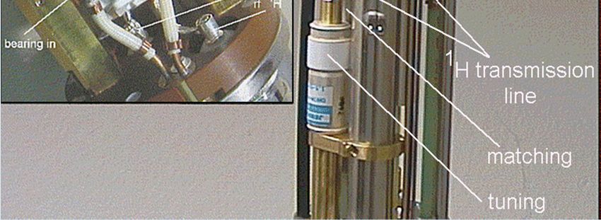
Overview
• probe types
• probe design
• Magic Angle Sample Spinning
   • rotor types and applications
   • rotor cap types and applications
   • sample change
• RF handling
   • tuning and matching
   • external RF filters
• temperature control -> dealt with in additional presentation
Types of MAS Probes

      High-resolution MAS
                                      Solid-state MAS
           (HRMAS)

                                 For WB             For SB
                                 magnets            magnets

     Double and triple-resonance           CRAMPS
     CP/MAS probes                         probes
     (H/X, H/X/Y, H/F/X)                   (VTN)
     MAS technology
     variable temperature features
     RF design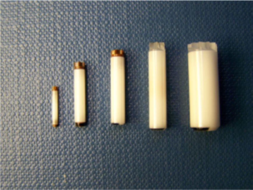
Standard Bore (SB) MAS probe

 proton trap

                               stator flip mechanism

                               bearing gas inlet
 BN stator
                                RF electronics
  RF coil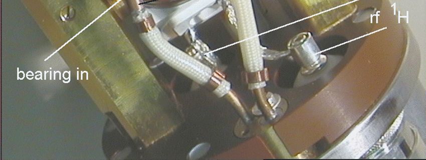
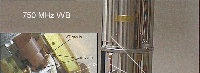
Wide Bore (WB) MAS probe

                           Principal design of
                           400-850 MHz WB
                           CP/MAS probes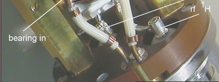
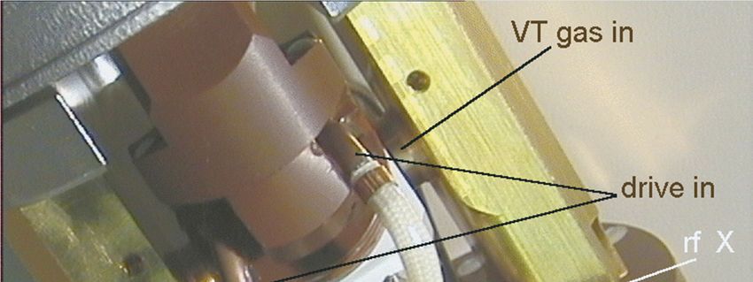
Wide Bore (WB) MAS probe

close view of
MAS stator
(DVT design)

Overview

MAS rotor types and specifications
  • sizes and maximum spinning speed
  • volume/sample confinement
  • cap materials and temperature ranges
  • special rotors for special samples/applications
MAS Rotors (Spinners)

MAS rotors with
1.3, 2.5, 3.2, 4, and 7 mm OD

          2.5         4.0

                                  maximum spinning speeds:
                                  1.3 mm: 67 kHz
                                  2.5 mm: 35 kHz
                                  3.2 mm: 24 kHz
                                  4.0 mm: 15 kHz
                                  7.0 mm: 7 kHz
    1.3         3.2         7.0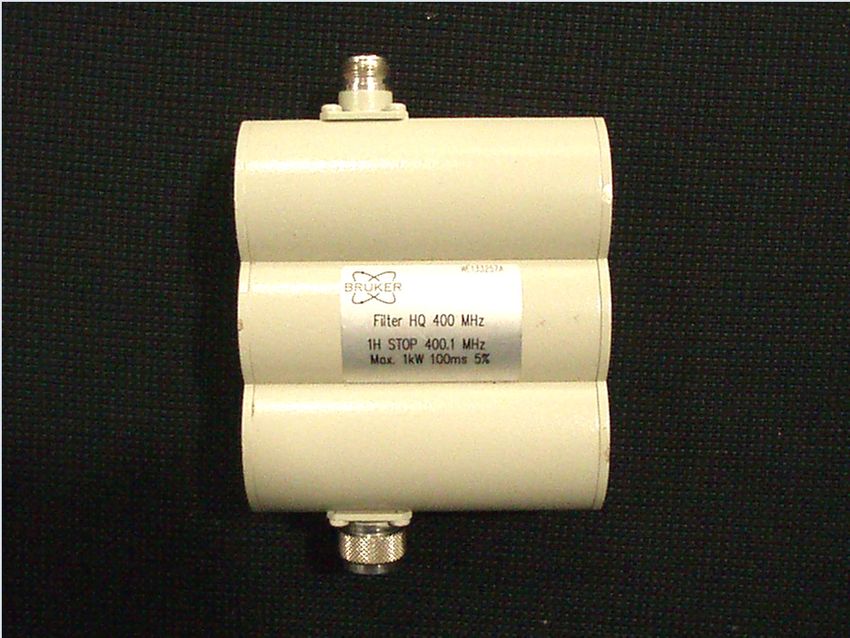
Maximum Spinning Speed

maximum spinning speed of MAS rotors determined by
  • pressure resistance of rotor material,
    pressure increases with the square of the spinning
    speed
  • speed of the circumfence must be less than the
    speed of sound, otherwise stall may occur,
    circumfence speed increases linearly with the
    spinning speed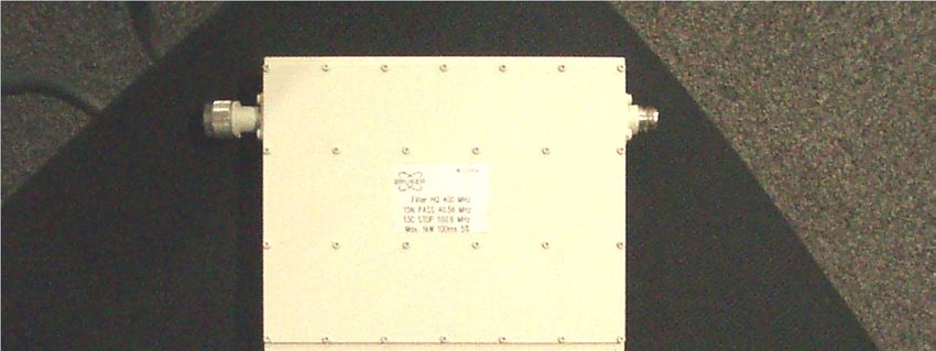
Reduced Volume 4 mm Rotors:HRMAS Type

for high resolution MAS or for high RF homogeneity

     50 µl, cylindrical                     12 µl, spherical

     1: rotor with solid bottom; 2: top plug with ventilation hole
     3: sealing screw; 4: rotor cap
Reduced Volume 4 mm Rotors: CRAMPS Type
for high RF homogeneity/small sample amounts
pull out screw
plug materials:
•Kel-F
•Teflon
•polyethylene
bottom plug (fixed)
top plug (removable)
also available for 7 mm rotorsReduced Volume 2.5 mm Rotors I
confinement by using long stem plugs
long stem top plug long stem bottom plug
standard top plug standard bottom plugReduced Volume 2.5 mm Rotors II
confinement by massive rotor bottom
standard top and bottom plug rotor
massive bottom rotorMAS-Spinners, Inserts, and Spinner Caps
diameter insert/cap for volume reduction volume
within coil
2.5 mm spinner with bottom cap 11 µl
with integrated bottom 8 µl
3.2 mm with integrated bottom 30 µl
with upper insert and massive bottom 14 µl
4 mm without insert, with thin bottom 71 µl
with upper insert and massive bottom 50 µl
with upper inserts and massive bottom 12 µl
7 mm without Insert, with thin bottom 240 µl
“CRAMPS – inserts“ 60 µlVT: Rotor Caps
ZrO2 Macor BN Kel-F VespelVT: Rotor Caps
Kel-F (polymer): ambient temperature ± , (shrinks when
cold, softens and deforms when hot), easy pull-out
BN (ceramic): high and low temperature, mechanically
delicate, glue in for tight fit
Macor (ceramic): high and low temperature,
mechanically delicate, glue in for tight fit
ZrO2 (ceramic): high and low temperature, mechanically
durable, easy pull-out, not so cheap ...
Vespel (polymer): high speed high temperature,
easy pull-outSpinner Caps: Materials and Application Ranges
spinner diameter material of rotor cap temperature range
2.5 mm Vespel -30 ... +80°C
3.2 mm Kel-F -10°C ... +50°C
Vespel -30 ... +80°C
Zirconia -140°C ... +300°C
4 mm Kel-F -10°C ... +50°C
Vespel -30 ... +80°C
Zirconia -140°C ... +300°C
Boron nitrid -140°C ... +300°C
7 mm Kel-F -10°C ... +50°C
Zirconia, Macor -140°C ... +300°C
Boron nitrid -140°C ... +300°CHigh Speed Rotors
high speed ZrO2 rotors:
7 mm: νrot,max= 8 kHz
4 mm: νrot,max= 18 kHz
high speed
7mm ZrO2
rotor/cap
standard
7mm ZrO2
increased wall thickness rotor/cap
(reduced active volume)Si3N4 Rotors
ZrO2 rotor
(7 mm, 4 mm)
main advantage of Si3N4:
higher thermal conductivity
(smaller temperature
gradients)
Si3N4rotor
(7 mm, 4 mm)Special MAS Rotors •sapphire rotors for light excitation •rotors for laser heating (no bottom, sample in ceramic insert) •stretch rotors for spinning sealed glass vials •...
MAS Rotors Summary

   type                            available for
   standard ZrO2                   7, 4, 3.2, 2.5   1.3
   CRAMPS (Kel-F, PTFE, PE)        7, 4,
   massive bottom, top insert         4, 3.2
   massive bottom, long stem cap              2.5
   high speed                      7, 4

   Si3N4                           7, 4

   sapphire                        7, 4,     2.5
Sample Insert/Eject for SB MAS Probe

                            stator flips from the
                            magic angle to the
                            vertical position for
                            eject/insert

                            exceptions:
                            2.5 mm (no flip)
                            3.2 mm (small angle flip)
Sample Insert/Eject for WB MAS Probe stator is static during sample change (no flip) sample is guided on its way in or out by a funnel like device
Cross Section View of the MAS Probe Stator
Coils for WB MAS probes
Frictional Heating in Air Bearings

  • air bearings are low friction bearing but are not
    friction free
  • friction causes heating of spinner and sample
  • effect is small or negligible at slow spinning and
    becomes important close to the maximum
    spinning speed
  • for sensitive samples: cool the sample
    appropriately
  • for precise temperature control perform a
    temperature calibration using an NMR
    thermometer
Frictional Heating in MAS probes
Temperature increase
due to air friction for
high spinning speeds
and accompanying
thermal gradients over
full zirconia rotors for
2.5mm MAS/DVT.
No cooling or heating
gas (VT) applied.General RF Design of MAS Probes
single Coil design
coil is simultaneously tuned to
one (single resonance probe) frequency
two (double resonance probe) frequencies
three (triple resonance probe) frequencies
dual Coil design Efree
inner coil is tuned to 1 or 2 frequencies,
outer coil (cavity) is tuned to protons onlyRF design of a WB CP/MAS probe
Probe Tuning and Matching

  tuning:
    adjust the resonance frequency of the probe circuit
    to the observe frequency (Larmor frequency)
  matching:
   adjust the probe impedance to the impedance of
   the other RF components (transmitter, cables,
   etc.),standard impedance: 50 Ohm
  purpose:
    maximum power delivered to NMR coil, i. e.
    maximum B1 field and minimum reflected power
    (which could be harmful to other components, e.g.
    the transmitter)
Wobbler response of a detuned probe
Wobbler response of a tuned probe
Set-up for probe tuning on the reflected RF power

 • Connect directional coupler between amplifier and
   probe
    • check ouput of connector close to probe
    • use external signal for triggering of scope

                                       to scope

                                                       probe
            amplifier/preamplifier
Shapes of reflected pulses
Rf switched on
reflected power
Rf switched off
badly tuned well tunedWobbler response of a probe after tuning on the reflected RF power (if component off 50 Ω or pulse detunes probe)
Some useful equipment

                        Directional coupler

                          Dummy load
                          attenuator
Radio Frequency Filters RF filters for double resonance experiments decoupling channel filters X-channel filters RF filters for H/X/Y triple resonance experiments X-channel filters Y-channel filters
Radio Frequency Filters

RF filters for H/X/Y triple resonance experiments
  X-channel filters
  Y-channel filters
Radio Frequency Filters

Why external RF-Filters?

MAS probe: single NMR coil, tuned to all Frequencies (H/X, H/X/Y,
  or even H/F/X/Y). Internal isolation, therefore, comparatively
  small.

X observe with Y decoupling (or vice versa):
   signal: µV to mV range
   decoupling: typical values:100 W (=200Vpp) to 300 W (343 Vpp)
⇒isolation better than 90 dB,
  this can be achieved with external filters only
Filters for H-F/X Double Resonance Experiments

 X BB                      1H   STOP             X
     preamplifier

                                                     probe
         1H                     1H               1H-19F
1H            preamplifier
                                bandpass

        (in case of HR preamplifier)
Filters for H-F/X Double Resonance Experiments
X BB 19F-STOP X
preamplifier
probe
19F 19F 19F 1H-19F
preamplifier bandpass
(in case of HR preamplifier)Filters for H-F/X Double Resonance Experiments
0-31P-LP
X BB X
preamplifier
(19F-1H STOP)
probe
19F 1H- 19F
1H/19F 1H-19F
or bandpass
1H preamplifier
(in case of HR preamplifier)Decoupling Channel RF Filters H/X experiments H/X or F/X or H+F/X (X observation) experiments F/X experiments
X Channel RF Filters, Double Resonance

H/X
experiments:

H/X or F/X
or H+F/X
(X observation)
experiments

F/X
experiments
RF Filter, Triple Resonance Experiments
X-Stopp
Y band
Y BB Y
preamplifier
pass
Probe
X BB X band X
preamplifier pass Y-Stopp
1H band pass
1H 1H preamplifier 1H
(19F band pass)
(19F) (19F preamplifier)
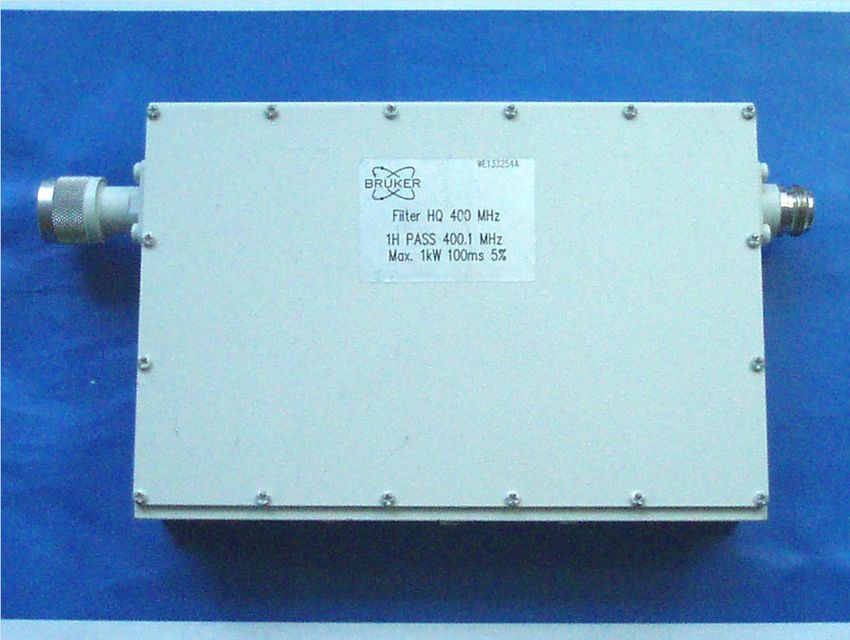
(bypass for HR preamplifier)Band Pass Filters, Triple Resonance Experiments
7Li-31P
band pass filter, 71Ga-87Rb
maximum input power: 1
kW 59Co-23Na
for 100 ms max.
duration 29Si
at 5% dutycycle,
(order No.: W1346 ...) 133Cs-2H
15N
0-15N LP
available 14NBand Pass Filters, Triple Resonance Experiments band pass filter for a given pass band may come in several designs, depending on the stop frequency requirements
Positioning of RF Filters

smaller filters:
male/female connectors:
directly connected to preamp

larger filters:
female/female connectors:
cable connection to preamp
www.bruker-biospin.com
You can also read