Standard Technical Specification Sodium Hypochlorite Storage and Dosing Facility - TMS1636 - Queensland Urban Utilities
←
→
Page content transcription
If your browser does not render page correctly, please read the page content below
Standard Technical
        Specification
Sodium Hypochlorite Storage
     and Dosing Facility

         TMS1636
REVISION CONTROL

Revision              Date                                           Revision Details                                  Responsible
Number                                                                                                                   Officer
     0          6/09/2016             Original                                                                        Jose C
     1          Dec 2016              Issued for Use – Stakeholder Comments Updated                                   Jose C

                                            DOCUMENT CONSULTATION

Revision              Date Sent                                     Name                                        Comments
Number
                                                                                                       Received       Incorporated
     0          30/09/16                      Harald Kemmetmuller                                      4/10/2016           Yes
     0          30/09/16                      Jeremy Torpy                                             14/10/2016          Yes
     0          30/09/16                      Ted Aston
     0          30/09/16                      Gerard Anderson

Doc ID:              TMS1636           Template Version:        1             Active Date:               20/01/2017            CONFIDENTIAL
Template Owner: Jose Castineyra                                               Template review due:       14/03/2021

Please note: Printed copies of this document should be verified for currency against online version.                           Page 1 of 25
Contents
REVISION CONTROL .......................................................................................................................................................1
DOCUMENT CONSULTATION .......................................................................................................................................1
1 SCOPE ..........................................................................................................................................................................4
2 REFERENCED DOCUMENTS .................................................................................................................................4
3 STANDARDS & REGULATIONS ............................................................................................................................5
3.1 STANDARDS ..................................................................................................................................................5
3.2 REGULATIONS ..............................................................................................................................................6
3.3 UNITS AND LANGUAGE .............................................................................................................................6
3.4 ACRONYMS AND ABBREVIATIONS.........................................................................................................6
4 GENERAL REQUIREMENTS ..................................................................................................................................7
4.1 MINIMUM CRITERIA ...................................................................................................................................7
4.2 MATERIALS ...................................................................................................................................................8
4.2.1 Corrosion Resistance ...................................................................................................................8
4.2.2 Adhesive, Sealants, and Gaskets ..................................................................................................8
4.3 PIPEWORK .....................................................................................................................................................8
4.4 CIVIL WORKS ................................................................................................................................................9
4.5 MECHANICAL WORKS ................................................................................................................................9
4.6 ELECTRICAL WORKS ..................................................................................................................................9
4.7 INSTRUMENTATION.................................................................................................................................. 10
4.8 TELEMETRY & CONTROL ........................................................................................................................ 10
4.9 SERVICES ..................................................................................................................................................... 10
4.10 FACILITY AND EQUIPMENT IDENTIFICATION AND LABELLING .................................................. 10
4.11 WARNING SIGNS ........................................................................................................................................ 10
4.12 ELEMENTS OF SODIUM HYPOCHLORITE STORAGE AND DOSING SYSTEM ............................... 11
4.13 MAINTENANCE ACCESS .......................................................................................................................... 11
5 TECHNICAL REQUIREMENTS ........................................................................................................................... 11
5.1 CHEMICAL DELIVERY BAY ..................................................................................................................... 11
5.2 LOCATION ................................................................................................................................................... 11
5.3 ACCESS......................................................................................................................................................... 12
5.4 ROLL OVER BUNDED DELIVERY AREA ............................................................................................... 12
5.5 SUMP AND DISCHARGE LINE (ROLL OVER BUND) ........................................................................... 12
5.6 SAFETY EQUIPMENT ................................................................................................................................. 13
5.7 TANKER POWER CONNECTION OUTLETS ........................................................................................... 13
5.8 CDU AREA ................................................................................................................................................... 14
5.8.1 Layout and Dimension ............................................................................................................... 14
5.8.2 Bund Floor and Wall .................................................................................................................. 14
5.8.3 Sump and Discharge Line .......................................................................................................... 15
5.8.4 Electrical .................................................................................................................................... 15
5.8.5 Lighting ...................................................................................................................................... 15
5.8.6 Chemical Manifest ..................................................................................................................... 15
5.9 CHEMICAL STORAGE TANK.................................................................................................................... 16
5.9.1 Material ...................................................................................................................................... 16
5.9.2 Structural .................................................................................................................................... 17
5.9.3 Access Hatch.............................................................................................................................. 17
Doc ID: TMS1636 Template Version: 1 Active Date: 20/01/2017 CONFIDENTIAL
Template Owner: Jose Castineyra Template review due: 14/03/2021
Please note: Printed copies of this document should be verified for currency against online version. Page 2 of 255.9.4 Tank Inlet and Outlet ................................................................................................................. 17
5.9.5 Level Indicator ........................................................................................................................... 18
5.9.6 Digital Display ........................................................................................................................... 18
5.10 DOSING SYSTEM ........................................................................................................................................ 18
5.10.1 Dosing Pumps and Pipework ..................................................................................................... 19
5.10.2 Pulsation Dampeners at Pumps .................................................................................................. 19
5.10.3 Depressuring, Flushing, and Draining ....................................................................................... 20
5.10.4 Pressure Indicator....................................................................................................................... 20
5.10.5 Double Containment of Filling and Dosing Lines ..................................................................... 20
5.10.6 Dosing Point .............................................................................................................................. 20
6 DOCUMENTATION ................................................................................................................................................ 20
6.1 DRAWINGS .................................................................................................................................................. 21
7 COMMISSIONING AND STARTUP...................................................................................................................... 22
7.1 SITE SUPPORT ............................................................................................................................................. 22
7.2 OPERATING AND MAINTENANCE INSTRUCTIONS ............................................................................ 22
8 SUPPLEMENTARY INFORMATION ................................................................................................................... 23
APENDIX A ........................................................................................................................................................................ 24
Doc ID: TMS1636 Template Version: 1 Active Date: 20/01/2017 CONFIDENTIAL
Template Owner: Jose Castineyra Template review due: 14/03/2021
Please note: Printed copies of this document should be verified for currency against online version. Page 3 of 251 SCOPE
This specification sets out the minimum requirement for the design, materials,
fabrication, inspection, testing and installation for a Sodium Hypochlorite Storage and
dosing facility for Sewage Treatment Plants (STPs).
2 REFERENCED DOCUMENTS
The following QUU Specifications apply
Document Number Title
CHE135 Pre-factory Inspection Test Checks – Switchboards
CHE305 Standard Variable Speed - Sewage Pumping Station (FAT)
TEM336 Power System Analysis Guidelines
TMS62 Preferred Equipment List – Electrical and Instrumentation
TMS76 Corrosion Protection for Electrical and Mechanical Equipment and
Structures
TMS78 Typical Switchboard Changeover Commissioning Plan
TMS849 Citect SCADA Configuration Standard
TMS1151 Preferred Equipment List – Control Systems
TMS1200 Electrical Installation - Technical Specification
TMS1201 Instrumentation Installation - Technical Specification
TMS1202 Control System Implementation for Network Assets
TMS1203 General Requirements for Hazardous Area Installation – Technical
Specification
TMS1222 Control Panels - Technical Specification
TMS1229 PLC Programming and Configuration Standard
TMS1406 LV Variable Speed Drives – Technical Specification
PRO307 Procedure Drafting Guidelines – Contract Requirements
TMS1434 Technical Specification for Steel Structures
TMS1437 Technical Specification for Civil Works
TMS1439 Technical Specification for Concrete Structures
TMS 1639 Technical Specification for General Mechanical Works
PRO395 SEQ Water Supply and Sewerage- D&C Code Asset Information QUU
Addendum
SEQ Water Supply and Sewerage Design & Construction Code (SEQ
WS&S D&C Code)
WI58 Arc Flash Assessment and PPE Selection
Doc ID: TMS1636 Template Version: 1 Active Date: 20/01/2017 CONFIDENTIAL
Template Owner: Jose Castineyra Template review due: 14/03/2021
Please note: Printed copies of this document should be verified for currency against online version. Page 4 of 253 STANDARDS & REGULATIONS
All equipment and workmanship shall conform to the most recent requirements of the
relevant statutory Local, State and Commonwealth Authorities and current applicable
Australian Standards. Alternatively, where no Australian Standard exists, work shall
conform to the most current and applicable International standard.
Where conflict exists between different Codes, Standards or Regulations, the most
onerous conditions of specification shall apply unless accepted otherwise in writing by
QUU.
The Supplier shall not deviate from the provisions of the relevant standard without first
obtaining agreement in writing from QUU Superintendent.
3.1 Standards
Particular standards and regulations relevant to the work include but are not necessarily
limited to the following:
Document Number Title
AS/ISO 1000 International System of Units (S.I.) and its Applications
AS 1159 Polyethylene pipes for pressure applications
AS1260 PVC-U pipes and fittings for drain, waste and vent application
AS 1275 Metric Screw Threads for Fasteners
AS 1319 Safety signs for the occupational environment
AS 1345 Identifications of the contents of pipes, conduits and ducts
AS 1460 Mechanical jointing fittings for use with polyethylene pressure pipes
AS1462 Methods of test for plastics pipes and fittings
AS1627.4 Metal Finishing – Preparation and Pre-treatment of Surfaces – Abrasive blast
cleaning of steel
AS 1657 Fixed platforms, walkways, stairways and ladders
AS 1722 AS/NZS 4129:2000 Fittings for polyethylene (PE)
AS 1939 Classification of Degrees of Protection Provided by Enclosures for Electrical
Equipment
AS 2033 Installation of polyethylene pipe systems
AS 2129 Flanges for pipes, valves and fittings
AS 3000 SAA Wiring Rules
AS 3500 Plumbing and drainage
AS 3735 Concrete structures retaining liquids
Doc ID: TMS1636 Template Version: 1 Active Date: 20/01/2017 CONFIDENTIAL
Template Owner: Jose Castineyra Template review due: 14/03/2021
Please note: Printed copies of this document should be verified for currency against online version. Page 5 of 25AS 3780 Storage and handling of corrosive substances
AS 3996 Access covers and grates
AS 4775 Emergency eyewash and shower equipment
AS/NZS 3000 Electrical Installations (Australian/New Zealand Wiring Rules)
AS/NZS 4129 Fittings for polyethylene (PE)
AS/NZS 4680 Hot-dip galvanised (zinc) coatings on fabricated ferrous articles
AS/NZS 4766 Polyethylene storage tanks for water and chemicals
AS 60417(IEC 60417) Graphical symbols for use on equipment
National Code of Practice for the Storage and Handing of Workplace
[NOHSC:2017(2001)]
Dangerous Goods
3.2 Regulations
The current regulations and statutory requirements of the State of Queensland,
Australia, apply.
3.3 Units and Language
AS/ISO 1000 (metric SI system) shall be used. All documentation and correspondence
shall be in the English language.
3.4 Acronyms and Abbreviations
Term Definition
AS Australian Standards
CDU Chemical Dosing Unit
EPDM Ethylene Propylene Diene Monomer
ESD Emergency Shutdown Device
FAT Factory Acceptance Test
FRP Fibre Reinforced Plastic
HDPE High-density polyethylene
HSE Health, Safety and Environment
ISO International Standards Organisation
ITP Inspection and Test Plan
MSDS Material Safety Data Sheet
NC Normally Closed
NO Normally Open
Doc ID: TMS1636 Template Version: 1 Active Date: 20/01/2017 CONFIDENTIAL
Template Owner: Jose Castineyra Template review due: 14/03/2021
Please note: Printed copies of this document should be verified for currency against online version. Page 6 of 25P&ID Process & Instrumentation Diagram
PE Polyethylene
PLC Programmable Logic Controller
PN Pressure Nominal, Pressure Rating
PPE Personal Protective Equipment
ppm Parts per million
PVC Polyvinyl Chloride
QA Quality Assurance
QUU Queensland Urban Utilities
RPEQ Registered Professional Engineer Queensland
RPZ Reduced Pressure Zone
SAT Site Acceptance Test
SCADA Supervisory Control and Data Acquisitioning
SDRL Supplier Data Requirements List
SLD Single Line Diagram
STP Sewage Treatment Plant
UNO Unless Specified Otherwise
UV Ultra-violet
VSD Variable Speed Drive
%w/vol weight/volume percent
4 GENERAL REQUIREMENTS
All equipment shall be constructed and tested in accordance with the appropriate
AS/IEC standards and SEQ code.
The scope of work of this contract is for the design, manufacture, supply, delivery,
installation, testing and commissioning of all electrical equipment. This includes the
incoming power supply system, communication, control, instrumentation, and all
necessary accessories and associated equipment, for the proper functioning of the
dosing system to be installed at the site.
4.1 Minimum Criteria
The CDU facility shall be designed:
• For minimum life duration of 20 years in the environment and for the duty
specified and on the Project Data Sheets.
Doc ID: TMS1636 Template Version: 1 Active Date: 20/01/2017 CONFIDENTIAL
Template Owner: Jose Castineyra Template review due: 14/03/2021
Please note: Printed copies of this document should be verified for currency against online version. Page 7 of 25• The equipment shall be suitable for a minimum of 5
years normal continuous operation without maintenance at the duty specified
and on the Project Data Sheets.
• Not cause interruption to the normal operation of the STP;
• Have complete chemical receiving, storage, transfer, and dosing systems, and
the necessary safety facilities;
• Be capable of automatic dosing and report alarms via SCADA;
• Be capable of local manual operation, and;
• Contain all spills of the chemical being used.
4.2 Materials
All materials shall be as detailed on the Project Data Sheets and referenced
specifications. When materials are not specified the Contractor may offer standard
materials suitable for the environment and operating and design conditions. All
materials shall be new and free of defects.
4.2.1 Corrosion Resistance
All internal parts in contact with the chemical substances (including spill areas) are
required to be corrosion resistant against the chemical involved. Design Engineer must
consider the corrosion effects and the installed micro environment or substance in
contact in selecting materials.
4.2.2 Adhesive, Sealants, and Gaskets
All adhesive, sealants and gaskets shall be resistant to oil and water, non-supportive of
microbial growth, and dimensionally stable. They shall also be resistant to chemical
attack by the dosing chemical.
All gaskets shall be made from butyl, Ethylene Propylene Diene Monomer (EPDM), or
Viton rubber materials.
4.3 Pipework
All pipework selected shall be designed specifically for use in the chemical industry and
resistant to chemical attack.
All pipes, including those in pipe trays and trenches, shall be labelled in accordance
with AS 1345.
Pipe trays located outside shall be supplied and installed with suitable covers.
Buried non-metallic pipes shall have continuous metal tape placed in the trench above
the pipe to allow detection.
All chemical dosing lines external to the CDU (above ground or buried) shall be
provided with secondary containment pipework (sleeved) arrangement OD63PE100.
Doc ID: TMS1636 Template Version: 1 Active Date: 20/01/2017 CONFIDENTIAL
Template Owner: Jose Castineyra Template review due: 14/03/2021
Please note: Printed copies of this document should be verified for currency against online version. Page 8 of 25In addition to this, all chemical dosing and/or water lines
passing through the CDU electrical controls room shall also be pipe-in-pipe (sleeved)
arrangement. The arrangement of these pipes shall allow a leak to be readily identified
and contained, and facilitate repair or replacement of the inner pipe. The arrangement of
the pipework shall allow a leak to drain into the CDU bund or the dosing point. Dosing
lines shall be kept to minimum length and changes in elevation shall be minimised to
avoid air locks and gasification.
The valves used for Sodium Hypochlorite dosing system shall be Georg Fischer (G+F)
products or approved equivalent, and of uPVC construction. Valves shall show direction
of operation and flow.
All valve material shall be suitable for the application. The check valve spring shall be
made of hastelloy C alloy. The actuated valves if any shall be electrically actuated.
The pressure rating of the valves shall be PN16 or higher as required for the application.
Valves shall be supplied with union or socket connectors for connection of pipe.
All valves shall be full-bore type and listed under the SEQ Code (G+F preferred).
These, along with other non-standard pipework fittings shall be double union type to
minimise damage during repair and maintenance.
All water lines coming from QUU mains shall be provided with Reduced Pressure Zone
(RPZ) valves to control the water pressure and prevent water flowing back into the
mains. A separate RPZ shall be provided to ensure backflow from the Chemical Dosing
Unit cannot enter the emergency shower and eye wash facilities.
Refer to QUU Technical Specification for General Mechanical Works TMS 1639
4.4 Civil Works
The design and construction of the civil works shall be in accordance with the
requirements contained in QUU’s Technical Specification TMS1437
4.5 Mechanical Works
The design and construction of the mechanical works shall be in accordance with the
requirements contained in the Parent Project Requirements Technical Specification,
SOW Document and QUU Technical Specification for General Mechanical Works TMS
1639.
4.6 Electrical Works
The design and construction of the electrical works shall be in accordance with the
requirements contained in TMS1200.
Doc ID: TMS1636 Template Version: 1 Active Date: 20/01/2017 CONFIDENTIAL
Template Owner: Jose Castineyra Template review due: 14/03/2021
Please note: Printed copies of this document should be verified for currency against online version. Page 9 of 254.7 Instrumentation
All instrumentation including level transmitters, flow transmitter, flow switches and
level switches shall comply with the QUU’s Instrumentation and Control TMS62 and
TMS1201
4.8 Telemetry & Control
The CDU is to be supplied as a package by equipment supplier with all necessary
control and instrumentation to meet the requirements set down in the functional
specification and all other scope documents. The CDU shall be designed for connection
into QUU’s Telemetry System.
Specific requirements of telemetry and control for a CDU are detailed in TMS1202 and
TMS1222, also in the Parent Project Requirements Technical Specification and SOW
Document.
4.9 Services
Services to the CDU shall include water supply, electrical power, telephone connection
(if required), and drainage. These services are to be identified as to their location
relative to the dosing unit.
Any water supplied to the CDU shall not be installed near electrical equipment.
4.10 Facility and Equipment Identification and Labelling
All equipment shall have a unique identification number. QUU designates unique
identification numbers for all its asset and associated equipment, and QUU will assign
these.
The Contractor shall mount a standard QUU facility asset sign on the outside of the
CDU area.
4.11 Warning Signs
Warning signs (UV stabilised ) shall be erected as required. These include, but are not
limited to the following:
• A Hazardous Chemical (HAZCHEM) warning sign with UN number and
chemical class to be placed on the main site entrances or on the CDU area as
well as the storage tanks, when a hazardous chemical is stored on site.
• Information panels as per current edition of the Australian Dangerous Goods
Regulation shall be placed in prominent and visible locations.
• As a minimum, there shall be one sign on the chemical storage tank, and
another on the inside of the door to the bunded area.
• Confined Space Entry Permit sign to be placed on the storage tank.
Doc ID: TMS1636 Template Version: 1 Active Date: 20/01/2017 CONFIDENTIAL
Template Owner: Jose Castineyra Template review due: 14/03/2021
Please note: Printed copies of this document should be verified for currency against online version. Page 10 of 25• Capacity of the storage tank stated on the tank.
• Other relevant OHS signs shall be installed in accordance with AS 1319. The
signs may include, but are not limited to, safety shower, eye wash station,
and non-potable water tap.
4.12 Elements of Sodium Hypochlorite storage and dosing system
A CDU shall consist of the following elements:
o Chemical tanker delivery bay;
o CDU, which contains two separate areas; One for the electrical control panel &
RTU, and the other a self bunded wet area room for the chemical storage tank,
dosing pumps and pipe work;
o Electrical control panel and RTU;
o Chemical storage tank(s);
o Dosing system;
o Pumps;
o Pipes;
o Valves;
o Instrumentation;
Specific requirements for each chemical dosing system and element of the CDU are
detailed in the following sections of this Specification.
A CDU Process and Instrumentation Diagrams (P&ID) is available as appendix at the
end of this document.
4.13 Maintenance Access
The concept design including the layout of the equipment inside the CDU area shall be
submitted to QUU for approval prior to construction.
This is to ensure that access hatches, level indicators, mixers, pumps and so on, can be
easily reached by personnel for maintenance and operation and that the contractor has
followed the safety in design process.
5 TECHNICAL REQUIREMENTS
5.1 Chemical Delivery Bay
A chemical delivery bay shall be designed and constructed to provide safe arrival,
parking, offloading, turning around, and departure of bulk chemical tanker trucks.
5.2 Location
The delivery bay shall be located adjacent to the CDU area. Unless otherwise specified.
Doc ID: TMS1636 Template Version: 1 Active Date: 20/01/2017 CONFIDENTIAL
Template Owner: Jose Castineyra Template review due: 14/03/2021
Please note: Printed copies of this document should be verified for currency against online version. Page 11 of 25The unloading point shall allow the chemical delivery tanker to
be fully inside the delivery bay when unloading. The unloading hose connection point
shall be located inside the CDU area, and shall be no more than 6 m from the tanker
connection point, as per the Dangerous Goods Code of Practice.
5.3 Access
The delivery bay and its access shall be large enough to accommodate a tanker to be
reversed into the bund and exit the site in a forward direction. The Contractor must
model the turn in radius for typical 10 Tonne rigid tanker truck
Alternatively, the access shall allow the tanker to drive through, make a safe turn around
and exit the site in a forward direction.
The contractor must ensure that the design of the fill point complies with the
requirements of the chemical supplier that currently has a supply agreements with QUU
5.4 Roll over bunded delivery area
The delivery bay shall be a concrete slab with a hump, to provide containment for any
spill or leaks.
The bund shall be designed as a water retaining structure in accordance with AS 3735
and AS 3780.
The bunded area shall be designed with a 1 in 75 grade towards the sump pit, such that
no pools of chemical will accumulate on either side of the bund.
Bund area floor must be profiled so than any liquid within the bund will fall away from
the base of the tank and collect in a 900x900x400 sump with FRP grated cover and
DN100 valved drainage pipe connected to stormwater The position of the drainage
valve must be visible, obvious and labelled to alert operators when left open. The
drainage valve must be accessible for maintenance from outside the bund area.
Any humps in the roadway at either end of the tanker delivery bay bund shall be are
compatible with delivery trucks.
The delivery bay and CDU arrangement must ensure any stormwater from the
surrounding roadway and ground shall be channelled away, and not flow into the
delivery bay bund.
5.5 Sump and Discharge Line (roll over bund)
A sump pit to collect liquid from the roll over bunded area shall be provided. It shall
have dimensions of 900x900x400 sump with FRP grated cover and DN100 valved
drainage pipe connected to stormwater The position of the drainage valve must be
visible, obvious and labelled to alert operators when left open. The drainage valve must
be accessible for maintenance from outside the bund area. It shall be located where it is
not subjected to vehicle loading outside the vehicle load area, but inside the bunded
volume area. It shall be fitted with a grate/cover, made from lightweight materials,
Doc ID: TMS1636 Template Version: 1 Active Date: 20/01/2017 CONFIDENTIAL
Template Owner: Jose Castineyra Template review due: 14/03/2021
Please note: Printed copies of this document should be verified for currency against online version. Page 12 of 25weighing no more than 15 kg, in accordance with AS 3996,
Class A. The weight limit shall be labelled where appropriate.
The sump shall drain by gravity (typically a 100 mm pipe) where feasible, to an
appropriate location.
5.6 Safety Equipment
The following safety equipment shall be provided:
o A safety shower and eyewash station, which complies with AS4775, located
within 2 to 7 m of the chemical filling connection point. This is typically
mounted to the inside of the CDU area. Long water lines to the safety shower
and eyewash station that are exposed to sunlight shall be lagged, to eliminate
risk of water being too hot for use.
o An additional eyewash station located inside the CDU bunded area shall also be
provided.
o A flow switch activated alarm to activate an audible and flashing light after the
shower has been on for 5 minutes. The alarm shall also be connected into the
control system to alert the remote site operators via SCADA that the safety
shower is in use.
o A permanent lit green LED light source shall be provided for improved
effectiveness of signalling eyewash and safety showers (Coolon EWL type).
o Eye wash safety showers to be full 316L SS construction.
o A UV resistant hose reel permanently attached to a water tap and capable of
reaching all parts of the CDU, including the unloading area.
o Emergency shutdown provision, capable of stopping the unloading operation, is
to be provided at least 10 m from the unloading point.
o Sufficient lighting to enable safe work beyond daylight conditions, particularly
for the chemical delivery activities.
o When the delivery bay is not adjacent to the CDU (that is, in a remote location),
an additional safety shower is required within 2 to 7 meters of the tanker
connection point (unobstructed egress).
5.7 TANKER POWER CONNECTION OUTLETS
Two permanently mounted electrical power outlets are required for unloading of the
dosing chemical. These power outlets are 415 V (32 amps) and 240 V (20 amps) UNO,
and are interlocked with the storage tank high-level switch, to prevent operation of the
tanker unloading pump on high-level.
They shall be located within 7.5 m of the filling hose connection point, and inside the
CDU area.
Doc ID: TMS1636 Template Version: 1 Active Date: 20/01/2017 CONFIDENTIAL
Template Owner: Jose Castineyra Template review due: 14/03/2021
Please note: Printed copies of this document should be verified for currency against online version. Page 13 of 255.8 CDU Area
A steel portal frame roof structure with a 900mm overhang shall be designed to
accommodate the chemical storage tank(s) and its bund, dosing equipment, and control
panel, along with the necessary control equipment, alarms and telemetry links. The
frame must be hot dipped galvanised and painted with a 50µm epoxy zinc phosphate
primer and minimum 400µm high build, high hardness, epoxy barrier coat protective
paint system.
5.8.1 Layout and Dimension
The CDU area shall consist of two separately accessible areas; a bunded dosing area for
chemical storage and dosing equipment, that is capable of containing any chemical
leaks or spills. The second is a control area for electrical controls, telemetry, and
document storage.
Normal working areas shall have immediate access to emergency egress out of the
bund.
5.8.2 Bund Floor and Wall
The chemical storage area inside the CDU portal frame shall be bunded and designed as
a water retaining structure in accordance with AS 3735. It shall have the capacity of at
least 110% of the total capacity of the largest tank located within the bund compartment
in accordance with AS3780.
The bund wall height shall be a maximum of 1 m for worst case emergency escape. The
need for high bund walls needs to be balanced against the more difficult access and
emergency egress and the overall size of the CDU area. The bund shall comply with
AS1657 for safe access.
A high level alarm (connected to SCADA) shall be installed in the bund, to alert the
operator that a spill may have occurred. The alarm set point shall be agreed with QUU,
and cause an automatic shutdown of the CDU.
The bunded area shall be designed with a 1 in 75 grade towards the sump pit such that
no pools of water/chemical will accumulate on the bund floor.
The bund wall and floor shall be adequately coated to protect the concrete. The floor
surface shall be non-slippery.
All pipework shall be run around the perimeter of the dosing area to minimise trip
hazards, and as far away from electrical wiring as practicable. With exception to the
bund drainage pipe, all pipes shall pass above the top of bund wall.
Refer to TMS1439 Technical Specifications for Concrete Structures.
Doc ID: TMS1636 Template Version: 1 Active Date: 20/01/2017 CONFIDENTIAL
Template Owner: Jose Castineyra Template review due: 14/03/2021
Please note: Printed copies of this document should be verified for currency against online version. Page 14 of 255.8.3 Sump and Discharge Line
To allow for the management of any chemical spills occurring in the bunded area, a
sump shall be provided. The fall within the bund shall drain to this sump. The sump
shall have dimensions of 900x900x400 sump with AS3996 Class B, FRP grated cover
and DN100 valved drainage pipe connected to stormwater. The position of the drainage
valve must be visible, obvious and labelled to alert operators when left open. The
drainage valve must be accessible for maintenance from outside the bund area. The
connecting pipe from the bund to the drain point shall be pressure rated and sealed with
a suitable chemically resistant coating to avoid chemical ingression into the concrete
wall.
The discharge line may be combined with the chemical delivery bay discharge line (see
Section 5.5 of this Specification).
5.8.4 Electrical
All electrical equipment, including wiring, shall be installed above the full chemical
bund level. All electrical equipment shall be capable of working when the bund is full of
liquid. As both water and the dosing chemicals are electrical conductors, safety of
personnel within the bund must be considered when designing the layout of electrical
equipment within the CDU area.
5.8.5 Lighting
The Contractor shall design and supply lighting system to comply with the relevant
Australian Standards. Lighting shall be designed to allow safe access and operation of
the asset at night time.
Energy efficiency, easy maintenance and reliability of the lighting system shall be taken
into consideration in the design. Light fittings shall be selected from suppliers listed in
TMS62, Preferred Equipment List, Electrical and Instrumentation.
The lighting installation shall meet all the applicable requirements of QUU’s Technical
Specification TMS1200.
5.8.6 Chemical Manifest
If the chemical is classified as Dangerous Goods, and the volume stored is above the
manifest quantity (i.e. >10,000 L), then a Hazardous Material (HAZMAT) box shall be
mounted just inside the site main entrance gate. A chemical manifest shall be provided
in the box and shall contain the following details:
• Date of preparation
• Name and contact details of Occupier / QUU
• Responsible Person
Doc ID: TMS1636 Template Version: 1 Active Date: 20/01/2017 CONFIDENTIAL
Template Owner: Jose Castineyra Template review due: 14/03/2021
Please note: Printed copies of this document should be verified for currency against online version. Page 15 of 25• Contact details for two people in case of emergency
• Details of dangerous goods storages including type, location, number and
volume of tanks
• Material Safety Data Sheet (MSDS) of the chemical
A site plan of the premises which includes:
• Location of essential site services, fuel and power isolation points
• Location of fire extinguisher and safety shower/eye wash facilities
• Location of the manifest
• Main entry and exit points
• Location and classes of dangerous goods storages and how they are identified
• Dosing area
• Location of all drains on site
• Nature of adjoining sewage pumping station
• Location of emergency assembly area
5.9 Chemical Storage Tank
Chemical storage tank(s) shall be provided for safe storage of the dosing chemical. The
preferred location of the tanks is in the corner furthest away from the electrical
equipment and the entry access.
The storage volume shall be calculated between the top of the tank discharge line to the
dosing pump, and the maximum fill level, measured at the bottom of the overflow line
at the top of the tank. Tanks shall be designed so that there is 10 % spare capacity
between the high high and overflow levels.
Tank overflow connections shall be designed to prevent siphoning of the tank contents
and shall discharge into bunds without excessive splashing.
Tank vents shall be located so that discharges do not present a hazard to other
equipment or operators.
The storage tank shall be designed and constructed to provide complete draining of the
tank and its connections. Equipment, such as access hatches, mixers and level sensors
shall be able to easily reached from the platform ladder for ease of operation and
maintenance.
5.9.1 Material
The storage tank shall be manufactured from high-density PE, spirally wound FRP or
other material suitable for the chemical specified. It shall be designed and constructed in
accordance with AS/NZS 4766 when it is made from PE, or EN 13121 for FRP. Where
the dosing chemical is a corrosive substance, the chemical storage tank shall be resistant
to chemical attack, and designed and constructed in accordance with the relevant
requirement of AS 3780. A minimum of 1.5 times the specific gravity of the fluid to be
stored in the tank shall be assumed for calculation of wall thickness requirement.
Doc ID: TMS1636 Template Version: 1 Active Date: 20/01/2017 CONFIDENTIAL
Template Owner: Jose Castineyra Template review due: 14/03/2021
Please note: Printed copies of this document should be verified for currency against online version. Page 16 of 25To avoid external corrosion, all welded brackets such as hold-
down lugs, pipe supports, and lifting lugs, shall be designed to allow water/chemical to
drain away without pooling.
The tank supplied shall be fitted out with the required branches, fittings, labelling, and
identification number. The UV resistant labels shall include, but is not limited to the
material of construction, the name of the manufacturer and the date of manufacture.
5.9.2 Structural
The tank shall be suitably reinforced and supported to withstand all forces, including
filling forces, without deforming when it is full. The tank shall be fabricated such that
the top of the tank is capable of supporting the weight of maintenance personnel as
required.
For a FRP tank, it shall be anchored and mounted on a suitable concrete plinth. Suitable
lifting lugs shall be fitted.
5.9.3 Access Hatch
For a covered tank with a volume capacity of 5,000 litres and under, a minimum of one
600 mm diameter access hatch shall be provided on the top of the tank.
For any other tank, the minimum dimension of the side access hatch is 600 mm
diameter. The side access hatch shall be hinged to the tank wall.
The hatch shall be made from lightweight materials, weighing no more than 15 kg, in
accordance with AS 3996, Class A. Weight limits shall be labelled where appropriate.
5.9.4 Tank Inlet and Outlet
Tank shall have the following pipework features but not limited to:
• One vent (breather) with minimum diameter of 50 mm on the apex of the tank
roof shall be supplied. The vent shall penetrate the roof and finish in a 180° bend
with the open end facing downward. The end of the vent pipe shall be covered
with a 1 mm mesh to prevent vermin ingress.
• One overflow branch with minimum diameter of 80 mm in the tank wall, 50 mm
down from the roof-wall joint. The overflow line diameter should be at least 1.5
times the diameter of the filling line. The overflow line shall be located such that
it prevents immersion of instruments and equipment located in the tank roof and
directs chemical safely away from operators and to the bund sump.
• One drain branch with minimum diameter of 50 mm shall be provided as close
to the tank floor level as practicable.
• One 50mm diameter fill pipe to the top side inlet from tanker unloading point,
complete with a fill valve. A 50 mm suitable male Kamlok fitting, with cover,
shall be supplied and installed at the tanker filling point. This pipe shall rise
vertically and then slope downwards towards the tank (1 in 100 fall). It shall
Doc ID: TMS1636 Template Version: 1 Active Date: 20/01/2017 CONFIDENTIAL
Template Owner: Jose Castineyra Template review due: 14/03/2021
Please note: Printed copies of this document should be verified for currency against online version. Page 17 of 25enter the top of the chemical storage tank, and be located
above the level of the overflow pipe.
• One suitably sized bottom side outlet. It shall be located 100 mm above the tank
floor.
• Associated valves on the outlet pipe shall be located before the flange.
• Automatic cut out during filling when the tank reaches High Level (90%).
• Isolation (stop) valves on each of the inlet and outlet connections.
• All branches on the tank shall finish with 150 mm or more from the tank wall or
roof, with a Table D or E flange of AS 2129.
5.9.5 Level Indicator
An Ultrasonic Level Transducer in accordance with TMS62, to show the level/quantity
of the contents inside the tank, shall be provided. The transducer shall be connected to
the telemetry system, to allow remote monitoring in accordance with TMS849.
In addition to the ultrasonic transducer, a hydrostatic level sensor shall also be provided
for High, High-High and Low conditions.
A level indicator shall be adjacent to the tank wall, in order to indicate actual liquid
level inside the tank during filling, and shall be visible from the filling/transfer point.
A weatherproof digital display shall also be installed at the filling transfer point, to
indicate the actual level during filling. An alarm system, consisting of a klaxon and
beacon shall also be installed at the filling transfer point, to alarm if tank has overflowed
during filling.
In addition, the overflow pipe shall be piped to the sump in such a way, that the tanker
driver can view the discharge point from outside of the bund, to indicate if the tank is
overflowing.
5.9.6 Digital Display
The digital display for tank level shall be suitable for operation with 24 VDC power
supply. It shall be equipped with sunlight readable LEDs, and a minimum reading range
of 10 m. It shall be suitable to display percentage values.
If installed outside the CDU area, the digital display shall have a minimum rating of IP
56, and shall be installed with suitable mounting accessories.
5.10 Dosing System
The required dosing system shall be designed to provide a reliable, continuous dosing of
metered volumes of chemical. All valves, fittings and pipework necessary for the proper
operation of the dosing system shall be provided. The piping shall be suitable for the
chemical conveyed. The system shall be capable of operating in both automatic and
local manual modes.
Doc ID: TMS1636 Template Version: 1 Active Date: 20/01/2017 CONFIDENTIAL
Template Owner: Jose Castineyra Template review due: 14/03/2021
Please note: Printed copies of this document should be verified for currency against online version. Page 18 of 255.10.1 Dosing Pumps and Pipework
A n+1arrangment configuration with identical duty and standby dosing pumps (brand,
type and capacity range) shall be provided for dosing. The switchover to the standby
pump shall be automatic via SCADA. Automatic changeover between pump duties shall
be configured on time as well as pump fault. Communication protocol with PLC shall
be Profibus DP.
The dosing pumps shall be of the mechanically or hydraulically operated, piston
diaphragm reciprocating-type, driven by an electric motor. Solenoid-driven pumps,
double simplex capabilities via multiplexing, and ganging of gearboxes are not
acceptable.
The pumps shall incorporate local indication of the set rate. Metering accuracy of the
pumps shall be better than 2% of the set rate at a variable suction head.
A dose rate turndown ratio of 1:100 by means of stroke speed control through accurate
speed control with position feedback shall be provided.
Each pump shall be fitted with an external pressure relief valve, vented back into the
calibration vent line or tank vent.
The dosing pump must have at least 2 volt free contacts to be used for fault output to the
PLC. One fault will be used to indicate that the pump has a general fault and is not able
to run. The other fault is to be used to indicate that the dosing pump has abnormal
flow/pressure correlation, indicating that there is a problem with the suction or
discharge of the pump. All fault output relays must move to the abnormal state when the
pump power supply is de-energised.
Pumps shall monitor pressure and flow, and shall incorporate features like automatic
detection of overpressure, burst pipe, cavitation and air bubbles in diaphragm.
Refer to TMS62 for approved equipment.
Adjustable pressure sustaining valves shall be incorporated on each discharge line from
the dosing pumps to maintain dosing accuracy over the range of operating depths in the
storage tank, and to act as anti-syphoning protection.
Duty and standby suction strainers with a maximum opening of 1 mm shall be provided.
Splashguards shall be installed around the duty and standby pumps to contain chemical
spray if dosing lines/pumps were to break.
5.10.2 Pulsation Dampeners at Pumps
Pulsation dampeners shall be provided in the discharge pipework from the dosing pump
and, shall be suitably sized for the displacement of the pump so that discharge pressure
fluctuation does not exceed 10%. The pulsation dampeners shall have a diaphragm
separating the air chamber from the liquid chamber. The air chamber shall be
pressurised, and be capable of re-pressurising by air pump via a Schrader valve.
Doc ID: TMS1636 Template Version: 1 Active Date: 20/01/2017 CONFIDENTIAL
Template Owner: Jose Castineyra Template review due: 14/03/2021
Please note: Printed copies of this document should be verified for currency against online version. Page 19 of 255.10.3 Depressuring, Flushing, and Draining
Adequate provision shall be made for draining of lines for maintenance. This typically
involves at least one drain valve on each of the suction and discharge sides of the pump.
These valves shall be piped to the sump. The valving shall be provided to allow for
flushing of the chemical dosing lines without dismantling the lines.
A 50mm Male polypropylene Kamlock fitting shall be provided at the chemical filling
line, and on all flushing points on the dosing line.
5.10.4 Pressure Indicator
A pressure indicator shall be installed on the discharge side of each pump. The
hydraulic oil type shall be used for process fluids that may damage the pressure
indicator. The purpose of the indicator is to enable setting of the pressure relief valve
and the loading/anti-syphon valve.
5.10.5 Double Containment of Filling and Dosing Lines
Chemical dosing lines are typically a pipe-in-pipe arrangement. The Contractor must
provide secondary containment pipework for all pipe that could potentially leak to a
location outside the storage bund. Care must be taken with the design and installation of
the outer pipe so that leaks from the inner pipe can be readily detected.
Concrete encasement of the lines when laid in ground is acceptable. Double
containment from within the bunded area through to the dosing point shall be
constructed in such a way to facilitate replacement of dosing line without excavation of
that section of pipe. PE pipe shall be considered secondary containment.
5.10.6 Dosing Point
The dosing point shall be installed with withdrawable injection quill with internal non
return valve for anti-siphon.
The use of shields to prevent splashing to nearby walls (where a corrosive chemical is
used)
6 DOCUMENTATION
The Contractor shall be responsible for providing all documentation as specified in the
Project General Specification for Supplier Documentation Requirements and the
Supplier Data Requirements List (SDRL) supplied by QUU.
Doc ID: TMS1636 Template Version: 1 Active Date: 20/01/2017 CONFIDENTIAL
Template Owner: Jose Castineyra Template review due: 14/03/2021
Please note: Printed copies of this document should be verified for currency against online version. Page 20 of 25Fabrication of any equipment shall not commence until QUU
has reviewed and approved calculations, drawings and any other design documentation.
6.1 Drawings
All design drawings shall be provided on QUU standard drawing template and cross
referencing between documents shall use QUU assigned drawing numbers. Drawings
shall be provided in native AutoCAD format as well as A3 size PDF. Refer to QUU
standard specification PRO307 Drafting Guidelines – Contract Requirements.
Doc ID: TMS1636 Template Version: 1 Active Date: 20/01/2017 CONFIDENTIAL
Template Owner: Jose Castineyra Template review due: 14/03/2021
Please note: Printed copies of this document should be verified for currency against online version. Page 21 of 257 COMMISSIONING AND STARTUP
The Contractor shall identify in their tender any special requirements or
recommendations for QUU support during commissioning and start-up of the
equipment supplied. The QUU final acceptance of the equipment will be subject to a
performance test once the equipment has been installed and commissioned.
7.1 Site Support
The Contractor shall provide in their tender details of their site technical support
capability. Contractors shall advise their nearest service representative and nearest
service facility to the project fabrication yard and the facility location.
7.2 Operating and Maintenance Instructions
The contractor shall supply Operating and Maintenance instructions for the equipment
supplied.
The instructions shall be fully detailed and cover all items supplied under the contract
and shall be indexed and cross referenced, as applicable.
The documents shall apply specifically to the plant being supplied and shall be specially
prepared where necessary. The instructions shall include comprehensive lists of all part
numbers of all items supplied.
Doc ID: TMS1636 Template Version: 1 Active Date: 20/01/2017 CONFIDENTIAL
Template Owner: Jose Castineyra Template review due: 14/03/2021
Please note: Printed copies of this document should be verified for currency against online version. Page 22 of 258 SUPPLEMENTARY INFORMATION
The Contractor must comply with the following attached documents:
• Appendices and Bibliography (where present).
• Equipment data sheets
• Template P&ID for Hypochlorite Storage and Dosing Facility
Doc ID: TMS1636 Template Version: 1 Active Date: 20/01/2017 CONFIDENTIAL
Template Owner: Jose Castineyra Template review due: 14/03/2021
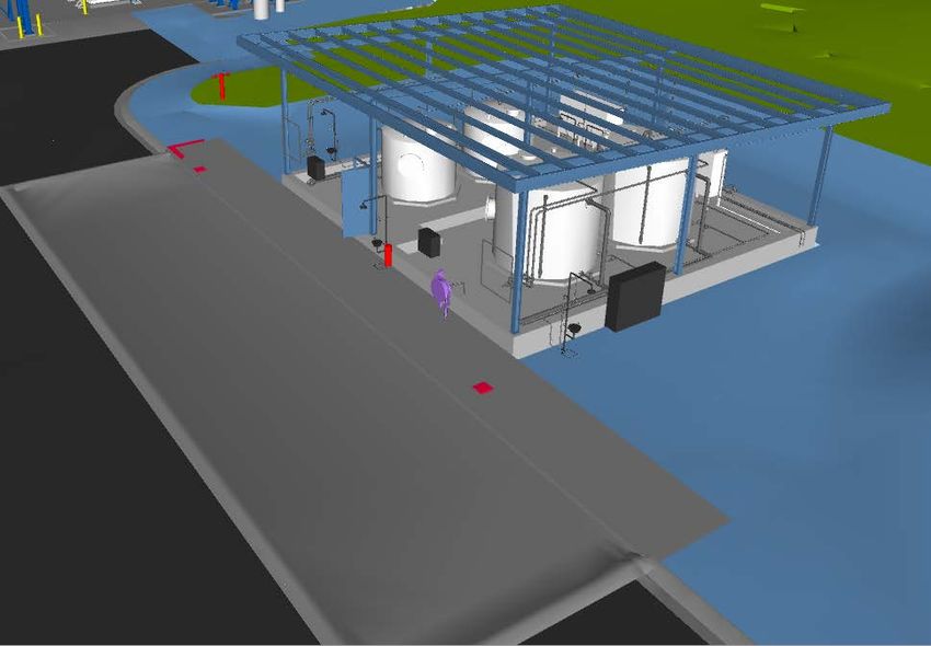
Please note: Printed copies of this document should be verified for currency against online version. Page 23 of 25APENDIX A Sodium Hypochlorite Storage and Dosing System example Doc ID: TMS1636 Template Version: 1 Active Date: 20/01/2017 CONFIDENTIAL Template Owner: Jose Castineyra Template review due: 14/03/2021 Please note: Printed copies of this document should be verified for currency against online version. Page 24 of 25
P+ID example for Sodium Hypochlorite Storage and Dosing System

Doc ID:              TMS1636           Template Version:        1             Active Date:             20/01/2017   CONFIDENTIAL
Template Owner: Jose Castineyra                                               Template review due:     14/03/2021

Please note: Printed copies of this document should be verified for currency against online version.                 Page 25 of 25
You can also read