STRUCTURAL HEALTH SENSORS
←
→
Page content transcription
If your browser does not render page correctly, please read the page content below

STRUCTURAL HEALTH SENSORS

                      STRUCTURAL HEALTH SENSORS

SENSORS SPECIFICALLY MADE FOR PERMANENT OUTDOOR
STRUCTURAL MONITORING

The Structural Health Sensors combine a 2-axis accelerometer
with a temperature sensor.
Their enhanced internal surge protection and electromagnetic
interference immunity makes them particularly suitable for
the permanent monitoring of tall outdoor structures.
The Structural Health Sensors can perform measurements in
extreme conditions ranging from -40°C to +85°C. They are
of course dust and watertight to IP66. We have a proven
track record of several thousands of such sensors operating
reliably around the world..

                                                                   V1.0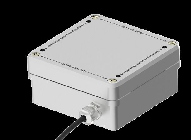
FIELD OF APPLICATIONS

Monitoring of Slender Structures
Slender structures, such as telecommunication towers, chimneys and elevated water reservoirs can be very
sensitive to dynamic wind loading. Indeed, wind-induced forces can cause significant dynamic response
which may lead to structural damages. In the case of telecommunication towers, they can also lead to signal
transmission distortion. Therefore, design criteria for slender structures must include dynamic stiffness which
depends on the main resonances frequencies and inherent structural damping. These characteristics must
be measured when the structure is first erected and compared with the design data. It is also recommended
that they are measured during maintenance activities.
In addition, in harsh/windy environments, the permanent monitoring of structural vibrations is recommended.
Indeed, the natural frequencies of a structure can be obtained from acceleration measurements and the shifts
of these natural frequencies values can be a good criterion for the evaluation of the structure’s integrity,
allowing for preventive action.

       KEY FEATURES                                         KEY BENEFITS
       • 4-20 mA current loops for signal immunity          • Robustness to environmental conditions
         and potentially long cable runs                    • Short-term or permanent long-term mon-
       • Enhanced surge protection                            itoring
       • Measurements down to DC for the mon-               • Monitoring of remote areas
         itoring of very low frequency structural
         modes

BLOCK DIAGRAM

                                                                                                          V1.0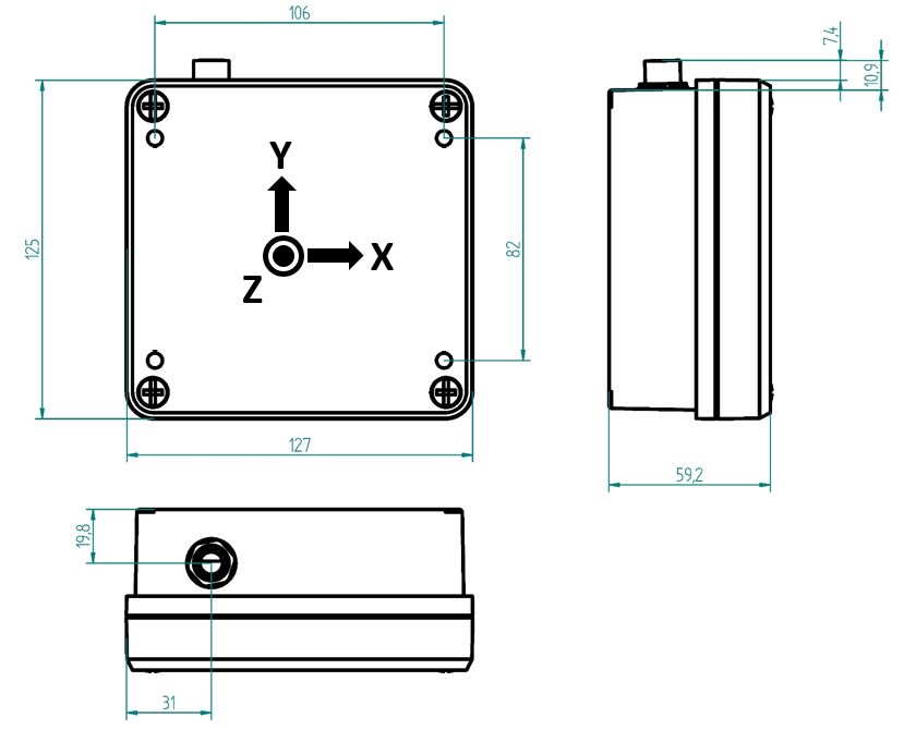
CHARACTERISTICS

                          Acceleration Channel Characteristics – High Resolution

                                             Test
                 Parameter                                    Min.          Typ.          Max.             Unit
                                           Condition
             Acceleration range                                              ±5                             g
                Sensitivity(1)
                                             T°=25°C          1.554         1.586         1.617           mA/g
Sensitivity change with Temperature         Delta from
                                                                            -100          -200        ppm/°C
                                              +25°C
                Zero-g level                                   -125           0           +125             mg
                                             T°=25°C
                                                               11.8          12.0          12.2            mA
        Zero-g level change with                                            ±0.5           ±2             mg/°C
             Temperature                    Delta from
                                              +25°C                         ±0.8                          µA/°C
                Non-linearity                                               ±0.5                           % FS
       Acceleration noise density            @ 40Hz                           8                           µg/√Hz
            Cross Axis Sensitivity                                            2             3               %
      2 order low-pass filter cutoff
       nd
                                             @ -3dB                          100                            Hz
               frequency
(1)   Sensitivity can be easily derived from 2 measurements at +1g and -1g as accelerometers measure DC

                          Acceleration Channel Characteristics – Standard Resolution

                                             Test
                Parameter                                     Min.          Typ.          Max.             Unit
                                           Condition
             Acceleration range                               ±5.4           ±6                             g
                 Sensitivity  (1)
                                             T°=25°C          1.205         1.339         1.473           mA/g
 Sensitivity change with Temperature        Delta from
                                                                            ±100                      ppm/°C
                                              +25°C
                Zero-g level                                  -450            0           +450             mg
                                             T°=25°C
                                                               11.4         12.0           12.6            mA
        Zero-g level change with                                            ±0.5                          mg/°C
                                            Delta from
             Temperature
                                              +25°C                         ±0.7                          µA/°C
                Non-linearity                                               ±0.5                          % FS
       Acceleration noise density            @ 40Hz                          50                           µg/√Hz
            Cross Axis Sensitivity                                            2             3               %
      2 order low-pass filter cutoff
       nd
                                             @ -3dB                          100                           Hz
               frequency
(1)   Sensitivity can be easily derived from 2 measurements at +1g and -1g as accelerometers measure DC

                                                                                                                  V1.0
Temperature Channel Characteristics
Test
Parameter Min. Typ. Max. Unit
Condition
Measurement range -40 +85 °C
Accuracy From 0 to -0.15 +0.15 °C
70°C
Outside the 0 -0.50 +0.50 °C
to 70°C range
Temperature noise density 0.01 °C/√Hz
2 order Butterworth low-pass filter
nd
1 Hz
cutoff frequency
Temperature Sensor Response Curve
Power Supply
Test
Parameter Min. Typ. Max. Unit
Condition
Voltage 20 24 28 VDC
Current 20 80 mA
V1.0DIMENSIONS
REFERENCE DIRECTIONS
V1.0CERTIFICATIONS
Electromagnetic Compatibility
Standard Limit / Level
Emission
EN 55011 30 MHz – 1 GHz
Radiated Emission Group 1 – Class A
FCC 47 Part 15 30 MHz – 1 GHz
Radiated Emission Class A
Immunity
EN 61000-4-2 4kV / contact
Electrostatic Immunity 2, 4 & 8kV /air
Criterion B
EN 61000-4-3 80MHz – 1 GHz @ 10V/m
Radiated, radio frequency, electromagnetic 1.4 – 2GHz @ 3V/m
field immunity
2 – 2.7GHz @ 1V/m
@ 80% AM 1kHz
EN 61000-4-4 2kV – 100kHz on signal lines
Electrical fast transient / burst immunity Criterion B
EN 61000-4-6 10V (150kHz-80MHz)
Immunity to conducted disturbances, induced Criterion A
by radio-frequency fields
EN 61000-4-8 Continuous field 30A/m
Power frequency magnetic field immunity Short duration field 100A/m
50 & 60Hz
Criterion A
Operating Temperature
Standard Limit / Level
IIEC 60068-2-14 Cycling between -40°C and +85°C
Change of Temperature
IEC 60068-2-1 Operation at -40°C (including cold start)
Cold
IEC 60068-2-2 Operation at 85°C
Dry Heat
V1.0ORDERING REFERENCE
NOTE
When ordering with cable connections, the cable is mounted at the factory. Please specify required length.
Standard cable gauge is 0.25 mm² (AWG24). Higher cable gauge might be required for long cable runs.
ENGINEERING SERVICES
• Other resolutions and/or measurement ranges
• Special coatings
• Special cables
• Integration with monitoring systems and cloud
platform
• Adaptations for underwater use
Rue du Trou du Sart 10 Tel. +32(0)81248100 | Fax. +32(0)81248101
B-5380 Fernelmont | Belgium info@micromega-dynamics.com
EU ID.:BE0466034916 www.micromega-dynamics.comYou can also read