STUDY ON THE STRAIN FIELD IN THE WAKE OF AN AIRFOIL
←
→
Page content transcription
If your browser does not render page correctly, please read the page content below
STUDY ON THE STRAIN FIELD IN THE WAKE OF AN AIRFOIL
                      Eszter Lukács1, Tamás Régert2, László Nagy3
              1.
                   Undergraduate, 2. PhD, Assistant Professor, 3. PhD student
       Budapest University of Technology and Economics, Mechanical Faculty,
                     Department of Fluid Mechanics, Hungary

ABSTRACT

This paper shows an initial study on the role of the strain, i.e. the symmetric part of
the velocity gradient tensor, in the formation of the cascade of the turbulent scales.
The present investigation is based on post-processing existing data produced by
means of Large Eddy Simulation. When turbulent flow is to be analyzed, vortices
and the dynamics of vortices are usually focused on. The turbulent energy cascade
is usually explained with the aid of the induced velocity field of the vortices
expressed by the Biot-Savart law. However the initial disturbances that leads to the
deformation of the vortex filaments, as well, as the stretching mechanism of them is
related to the strain field. The flow field around a wing section was determined and
the eigenvalues and eigenvectors of the strain tensor were calculated for a time
instant. Iso-surfaces of the eigenvalues of the strain tensor are compared to those of
the Q criterion.

1. INTRODUCTION

    The behavior of the vortices, that rolled up from a shear layer are characterized
by severe three-dimensional instability leading to their deformation and break-up.
The mechanism of the brake-up of the initially well organized vortex tubes is based
on the induced velocity field of the vortex filaments [1,2].
    A plane shear layer is known to be unstable for any upstream disturbances. The
appearance of the so called Kelvin-Helmholtz waves is a primary instability, which
basically means the reorganization of the originally evenly distributed vorticity into
regions of high vorticity (cores) and regions of low vorticity or high strain (braids).
The flow, characterized by spanwise vortices is two-dimensional in this stage, but it
may go under further development.
    A possible way of the flow development is suggested by Lasheras and Choi [2].
According to them a severe three-dimensional instability originates in the braids.
The small upstream disturbances deform the weak vortex tubes in the braids, which
under the effect of the strong strain field, start to be stretched in the direction of the
flow. Due to mutual interaction of the weak and the strong vortex tubes, the strong
ones get wavy and the weak ones turn in the direction of the flow, by this creating a
system of streamwise vortices superimposed on the spanwise ones. Whenever the
streamwise vortices appear in the core zone, they go through further interaction,
which finally results in the break-up of the coherent structures.
    As the strong strain field in the braids is said to play a key role in the appearance
of the streamwise structures, characteristics of the strain tensor will be examined
later on in this paper.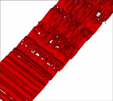
2. DESCRIPTION OF THE COMPUTATIONAL MODEL
The finite volume method based CFD code computation has been carried out in
three domains of different lengths given by the non-dimensional parameter of chord
length (c) about flow pattern characterized with Reynolds number of 1.22.105
around a RAF6 type airfoil [3]. The airfoil positioned 0.5c from the inlet. The
dimensions of the domains are 3cx1cx1c, 3cx1cx0.125c and 3cx1cx0.125c length
stream wise, wall-normal direction and spanwise direction, respectively. The
domains bounded with path lines computed from previous RANS simulation with
k-e turbulent model in airfoil wall normal direction [4]. Each domain was meshed
using O-H type structured grid using 2.006.150 hexahedral cells. The mesh was
appropriately refined in the direction to the walls of the airfoil by an expansion ratio
of approximately 7% to enable the accurate resolution of the boundary layer. The
wall normal size of the first cells attaching to the airfoil is linearly increasing along
the chord (both on the suction and pressure side) starting from 10-4c to 2.10-4c
height. This resolution corresponds to cell sizes in wall unit (y+) less than 1 in
99.6% of the domain. The equi-angle skew of none of the cells exceed the value of
0.67, which is appropriate for the numerical schemes used in this study. The
FLUENT 6.2 solver [5] was applied using cell centered collocated variable
arrangement, implemented for unstructured grid. For this constant density
simulation segregated solver was used for the sequential solution of the governing
equations. Second-order upwind discretization scheme was applied for the pressure
while for the momentum the bounded central differencing scheme (BCD) was
chosen. The pressure-velocity coupling was satisfied with fractional step method
(FSM) [6,7] in agreement with the applied non-iterative time-advancement (NITA)
for the transition control of the solver [5]. To solve the equations and calculate the
turbulence phenomena the Smagorinsky-Lilly based large-eddy simulation was used
with dynamic stress model [8,9] with a time-step of 3.5.10-6s.
The final judgment of the errors relied on monitoring of representative physical
parameter like the drag coefficient and lift coefficient and the area-weighted
averaged kinetic energy in the domain as well.
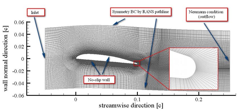
The applied boundary conditions can be seen in Figure 1. At the inlet boundary
uniform streamwise velocity (calculated from the 2D RANS calculation [4])
without any perturbation algorithm modeling fluctuating velocity algorithm was
applied. The pressure at the boundaries can be interpolated from the domain. The
wall of the airfoil was modeled as no-slip wall. For the outflow section,
homogenous Neumann conditions were applied for velocity and pressure. Specified
pressure gradient periodic condition was applied in span-wise direction to model the
three dimensional flow around the airfoil.
The simulations were compared with in-house hot-wire, laser Doppler
anemometry and pressure measurements in an NPL type wind tunnel. The bases of
the comparison were six velocity profiles perpendicular to the suction side and three
profiles perpendicular to the pressure side and three profiles in the wake, 0.1c, 0.25c
and 0.5c behind the airfoil.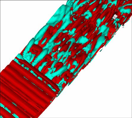
Figure 1. Applied boundary conditions in the LES

   The pressure was measured on both surfaces of the airfoil in 17 pressure taps. In
both parameters the LES results have shown better agreement than RANS with k-ε
and k-ω turbulence model [4]. But the pressure-coefficient is still over predicted by
simulation.

3. THE STRAIN TENSOR AND ITS EIGENVALUES

    From basic considerations of fluid mechanics it has been derived that strain
plays key role in the mechanics and energy budget of fluid flow, as it has strong
relation with the viscous forces and energy dissipation. The definition of the strain
tensor can be seen in Eq.(1).
                               Sij =
                                       1
                                         (∂ j u i + ∂ i u j ) ,                       (1)
                                       2
where Sij is an element of the strain tensor, ui [m/s] is the ith component of the
instantaneous velocity ( u 1 = u x , u 2 = u y ; u 3 = u z using the notation of Cartesian
coordinates), i, j =1,2,3. The trace of this tensor is the equation of continuity for
incompressible flows. It can be shown that the second invariant is equivalent to the
dissipation rate of the turbulent kinetic energy [10]. As the tensor of strain is
symmetric and all elements of it are real, it has three real eigenvalues and three
orthogonal eigenvectors. It is trivial that in two-dimensional flow, the strain tensor
has two eigenvectors, out of which, the first is oriented in 45° to the tangent of the
streamlines, while the second is oriented orthogonally in 135° to them. In three-
dimensional flows, there are three eigenvectors and the corresponding three
eigenvalues are usually denoted and called as follows: α elongational, β
intermediate, γ compressional. Due to the continuity for incompressible flows, α >
0, γ < 0 and β can be either negative, or positive. The intermediate eigenvalue, β, is
zero for two-dimensional flow or at least, for two-dimensional strain state. If β > 0
then the fluid element is stretched in the third direction and the element takes a
sheet-like shape, while in case of β < 0 the element is compressed and it takes tube-
like shape [10, 11]. The eigenvalues and eigenvectors of the strain-rate tensor were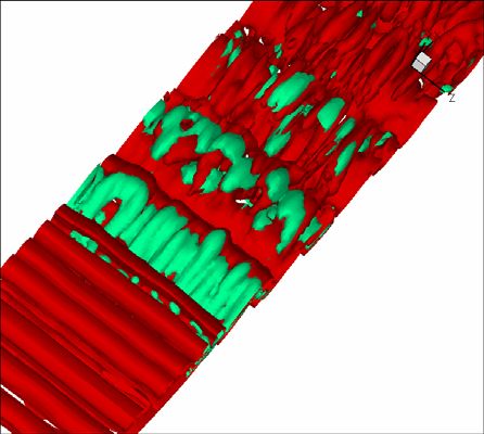
computed based on the Jacobi transformation for symmetric matrices [12]. In the
following section a time instant of the LES computation is analyzed.

4. DESCRIPTION OF THE FLOW FIELD, VORTEX AND STRAIN
STRUCTURES

    An effective way to examine the structure of a turbulent flow is to analyze the
existing vortices and their dynamics. For the visualization of vortices in the
investigated flow, the Q-criterion was used (Figure 2). The light color stands for
positive Q-isosurfaces, when vorticity dominates over strain, while the dark color
stands for negative Q-isosurfaces, when strain dominates over vorticity. From
Figure 2a it can be observed that the flow on the suction side of the wing is purely
characterized by spanwise vortices. In the first three main structures of the wake
spanwise vortices still dominate, but later streamwise vortices appear, superimposed
on the spanwise ones (Figure 2b). Another important observation is that strong
strain field appears exactly between two vortices, which can be clearly seen on the
wing and somewhat less clearly in the wake. Both the structure of the flow field and
the location of the strong strain field is in good accordance with the formerly
mentioned observations of Lasheras and Choi [2].

                             (a)                                               (b)
         Figure. 2 Positive and negative Q-isosurfaces (a) on the wing, (b) in the wake

    To find the role of the strain field in the evolution of the flow structure, the Q-
isosurfaces and the isosurfaces of the three eigenvalues of the strain-rate tensor
were compared. Figure 3a shows only the Q-isosurfaces, as a basis of comparison,
while on Figure 3 b, c and d it appears together with first, the positive second and
the negative second eigenvalues, respectively. Based on previous statements the
first (elongational) eigenvalue is expected to be situated between high vorticity
regions. This is supported by the second big structure of Figure 2b. The first
structure seems to contradict this statement, however it behaves on the same way,
only the iso-value corresponding the visible organization of the structures is higher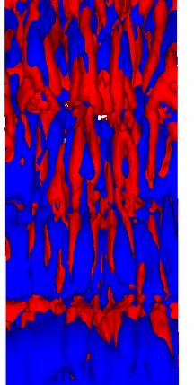
than in case of the represented one. The first and the third eigenvalues were found
to be approximately coincident, and of the same order.

                     (a)                                               (b)

                     (c)                                                (d)
    Figure. 3 (a) Q-isosurfaces (b) Q-isosurfaces (light) with first eigenvalue (dark color) (c)
  Q-isosurfaces (dark color) with second (light color), positive eigenvalue (d) Q-isosurfaces
                        with second (light color), negative eigenvalue

    The second eigenvalues also seem to have a strong relationship with the Q-
structures of the flow. Figure 3c shows that right after the trailing edge the positive
second eigenvalue coincides quite well with the Q-isosurfaces, from which we can
suppose, that regions of high vorticity tend to be sheet-like. From Figure 3d it turns
out that negative second eigenvalues mainly appear between the Q-structures, which
suggests a tube-like deformation of fluid elements there. This arrangement of sheet-
like and tube-like elements seems to be logical, as if two elements are stretched in
the x-z plane, the element between them has to be compressed in the z-direction and
elongated in the x-direction because of its constant volume. The first and third
eigenvalues are one order of magnitude higher than the second ones that indicates
two dimensional strain in the three dimensional flow field.
CONCLUSIONS
The structure of the iso-surfaces of the eigenvalues of the strain tensor was
shown in this paper using the flow in the wake of an airfoil, computed by means of
Large-Eddy simulation. The most significant components of the strain can be
related to its first and third eigenvalues, the iso-surfaces of which, show some
overlap between regions of high strain and high vorticity. This overlap might play a
role in the vortex stretching and vortex deformation that finally governs the
turbulent cascade process. It was found that the strain was mainly two dimensional
in the three dimensional flow field which is concluded from the low value of the
second eigenvalue that is responsible for three dimensional strain effects. The iso-
surfaces belonging to the positive and negative values of the second eigenvalue of
the strain tensor showed counter-phase arrangement. The sheet-like deformation
occurs mainly in the high vorticity regions, while tube-like deformation is placed
between the vortices. The sheet-like deformation might indicate a way of more
effective specific area increase that can be important for multi-component reactive
flows.
ACKNOWLEDGEMENT
Authors of this paper wish to express their thanks for the LES group of the
Deparment of Fluid Mechanics for providing the flow field to be analyzed here.
Special thanks to Péter Tóth for the implementation of the algorithm for the
computation of the eigenvalues and eigenvectors [12] into FLUENT.
REFERENCES
[1] J.C. Lasheras, J.S. Cho, T. Maxworthy: On the origin and evolution of streamwise vortical
structures in a plane, free shear layer, J. Fluid Mech., Vol. 172, 1986
[2] J.C. Lasheras, H. Choi: Three-dimensional instability of a plane free shear layer: an experimental
study on the formation and evolution of streamwise vortices, J. Fluid Mech., Vol. 189, 1988
[3] J. Gruber: Ventilátorok, Műszaki Könykiadó, 1966
[4] L. Nagy, J. Vad, M. M. Lohász: RANS Simulation of RAF6 Airfoil, Gépészet 2006, 2006
[5] Fluent 6.3 User Manual, 2006
[6] S. Armsfield, R. Street: The Fractional-Step method for the Navier-Stokes equations on staggered
grids: Accuracy of three variations, Journal of Computational Physics vol.153, pp660-665, 1999
[7] H. M. Glaz, J. B. Bell, P. Colella: An analysis of the Fractional-Step Method, Journal of
Computational Physics vol.108, pp51-58, 1993
[8] J. Smagorinsky: General circulation experiments with the primitive equations, Mon. Weather Rev.
Vol. 91, pp99-164, 1963
[9] Sung-Eun Kim: Large Eddy Simulation Using Unstructured Meshes and Dynamic Subgrid-Scale
Turbulence Models 34thAIAA Fluid Dynamics Conference and Exhibit, Portland Oregon, 2004
[10] B-C. Wang, D. J. Bergstrom, J. Yin, E. Yee: Turbulence topologies predicted using large eddy
simulations, Journal of Turbulence, Vol. 7, No. 34, 2006
[11] J. G. Brasseur, W. Lin: Kinematics and dynamics of small-scale vorticity and strain-rate structures
in the transition from isotropic to shear turbulence, Fluid Dynamics Research, 36 (2005), pp 357-
384, 2005
[12] W. H. Press, S. A. Teukolsky, W. T. Vetterling, B. P. Flannery: Numerical Recipies in C (The art of
scientific computing), second edition, Cambridge University Press, ISBN 0-521-43108-5, 1997You can also read