TAC II SCADA System
Installation Planning Guide
←
→
Page content transcription
If your browser does not render page correctly, please read the page content below
TAC II SCADA System Installation Planning Guide

TAC II SCADA System
Installation and Planning Guide
Copyright 1992-2015
All Rights Reserved
Data Flow Systems, Inc.
605 N. John Rodes Blvd., Melbourne, FL 32934
Phone 321-259-5009 • Fax 321-259-4006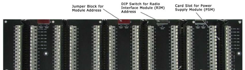
NOTICE

Data Flow Systems, Inc. assumes no responsibility for any errors
that may appear in this document nor does it make any commitment
to update the information contained herein. However, we welcome
questions regarding the information contained in this document.

Data Flow Systems, Inc. also reserves the right to make changes to
the TAC II RTU and its associated modules and to the information
contained in this document at any time, without notice.

            This document last revised July 11, 2015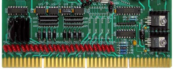
T ABLE OF C ONTENTS

Chapter 1: TAC II SCADA System Overview ........................................................................................1
Purpose of This Guide...................................................................................................................................................... 1
SCADA System.................................................................................................................................................................. 1
The TAC II SCADA System ........................................................................................................................................... 2
TAC II Communications.................................................................................................................................................. 3
   Communication Methods ......................................................................................................................................... 3
   Communication Protocols........................................................................................................................................ 4
The Central Site and RTUs .............................................................................................................................................. 5
   Hyper SCADA Server ............................................................................................................................................... 5
   System Access............................................................................................................................................................. 6
   Central Terminal Unit (Master Radio) .................................................................................................................... 7
   Forwarding Terminal Unit (FTU) ........................................................................................................................... 7
   The Remote Terminal Unit (RTU).......................................................................................................................... 8

Chapter 2: Function Modules and PLC Devices ................................................................................. 11
Overview........................................................................................................................................................................... 11
   Communication and Power Supply Modules ...................................................................................................... 11
   Digital Modules ........................................................................................................................................................ 11
   Analog Modules........................................................................................................................................................ 12
   PLC Devices ............................................................................................................................................................. 12
What Can I Monitor and Control?................................................................................................................................ 12
   Digital Inputs ............................................................................................................................................................ 12
   Digital Outputs......................................................................................................................................................... 12
   Analog Inputs ........................................................................................................................................................... 13
   Analog Outputs ........................................................................................................................................................ 13
   Using the Information............................................................................................................................................. 13
Descriptions of Function Modules and PLC Devices............................................................................................... 14
   Analog Control Module (ACM002) ...................................................................................................................... 15
   Analog Monitor Module (AMM002) .................................................................................................................... 16
   Bus Extender Module (BEM001).......................................................................................................................... 17
   Digital Control Modules (DCM003-1 through -6) ............................................................................................. 18
   Digital Monitor Module (DMM002)..................................................................................................................... 20
   Fiber Interface Module (FIM001) ......................................................................................................................... 21
   Power Supply Module (PSM003-1)....................................................................................................................... 22
   Programmable Logical Control Module (PLC) ................................................................................................... 23
   Radio Interface Module (RIM006) ........................................................................................................................ 27
   RDP180-C (Cellular RTU)...................................................................................................................................... 28
   Solar Power Module (SPM002).............................................................................................................................. 29
   Telemetry Control Unit (TCU001)........................................................................................................................ 30
   Telemetry Interface Module (TIM007)................................................................................................................. 31

Chapter 3: Pre-Installation Planning ...................................................................................................33
Introduction...................................................................................................................................................................... 33
Radio Frequencies and Licensing.................................................................................................................................. 33
    Frequencies ............................................................................................................................................................... 33
    Licensing.................................................................................................................................................................... 34

                                                                                          i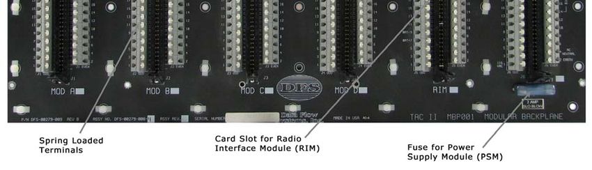
Table of Contents

Site Surveys .......................................................................................................................................................................34
     Central Site.................................................................................................................................................................34
     Remote Sites ..............................................................................................................................................................35
OSHA/Safety Issues .......................................................................................................................................................36
     Confined Space Operations ....................................................................................................................................36
     Lockout / Tagout Procedures ................................................................................................................................36
     Bloodborne Pathogens ............................................................................................................................................37

Chapter 4: Central Site Installation ..................................................................................................... 39
Introduction ......................................................................................................................................................................39
Hyper SCADA Server & Primary Operator Workstation .........................................................................................39
The CTU and Central Antenna Tower.........................................................................................................................40
Connecting the Hyper SCADA Server to the CTU ...................................................................................................40
    Power Supply for the CTU .....................................................................................................................................41

Chapter 5: Remote Site Installation .................................................................................................... 43
Introduction ......................................................................................................................................................................43
Phase I: Antenna Tower Erection & Preliminary Site Work ....................................................................................43
    Assemble Antenna and Tower ...............................................................................................................................44
    Set Antenna Tower...................................................................................................................................................44
    Mount Enclosure......................................................................................................................................................44
    Ground Tower & Align Antenna...........................................................................................................................45
Phase II: Conduit & Panel Work...................................................................................................................................45
    Running Conduit ......................................................................................................................................................45
Phase III: Pulling Wire & Wiring I/O Points .............................................................................................................46
    Wiring the Power Supply Module..........................................................................................................................46
    Wiring a Digital Monitor Point ..............................................................................................................................47
    Wiring a Digital Control Point ...............................................................................................................................48
    Wiring a Pulse Accumulator Point on a Digital Module (DCM/DMM) ........................................................49
    Wiring an Analog Monitor Point ...........................................................................................................................50
    Wiring an Analog Control Point ............................................................................................................................52
    Wiring the RTU Side................................................................................................................................................53
    Wiring a Bus Extender Module (BEM) ................................................................................................................55
    Wiring a Solar Power Module (SPM) ....................................................................................................................57
    Wiring the Control Panel Side ................................................................................................................................58

Chapter 6: Module Testing, Alignment & RTU Configuration.......................................................... 59
Test Wiring........................................................................................................................................................................59
    Digital Monitor Test Card (DMTM001)...............................................................................................................59
    Digital Control Test Card........................................................................................................................................59
Install Modules .................................................................................................................................................................59
Test VSWR........................................................................................................................................................................60
Align Antenna...................................................................................................................................................................60
Final Checkout of the RTU Site ....................................................................................................................................60
Configuring the RTU into the Central Site ..................................................................................................................60

Chapter 7: RTU Input / Output (I/O) Sheets.................................................................................... 63
Analog Control Module (ACM002) ..............................................................................................................................63
Analog Monitor Module (AMM002) ............................................................................................................................64

                                                                                          ii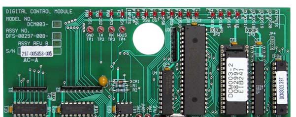
Table of Contents

Bus Extender Module (BEM)........................................................................................................................................ 65
Digital Control Module (DCM003-1)........................................................................................................................... 66
Digital Control Module (DCM003-2)........................................................................................................................... 67
Digital Control Module (DCM003-3)........................................................................................................................... 68
Digital Control Module (DCM003-4)........................................................................................................................... 69
Digital Control Module (DCM003-5)........................................................................................................................... 70
Digital Control Module (DCM003-6)........................................................................................................................... 71
Digital Monitor Module (DMM002) ............................................................................................................................ 72
Fiber Interface Module (FIM001)................................................................................................................................. 73
Power Supply Module (PSM003) .................................................................................................................................. 74
Programmable Logical Control Module (PLC001) .................................................................................................... 75
Programmable Logic Controller (PLC033) ................................................................................................................. 76
Pump Control Module (PCM001) ................................................................................................................................ 77
Radio Interface Module (RIM006)................................................................................................................................ 78
Solar Power Module (SPM002) ..................................................................................................................................... 79
Telemetry Interface Module (TIM007) ........................................................................................................................ 80
Telemetry Control UNIT (TCU001)............................................................................................................................ 81
Wire Color Abbreviation Chart..................................................................................................................................... 81

Index....................................................................................................................................................83

Table of Figures
Figure 1: Typical TAC II SCADA System..................................................................................................................... 2
Figure 2: Modular Backplane ......................................................................................................................................... 10
Figure 3: Modular Backplane Installed in 200 Series RTU ....................................................................................... 10
Figure 4: Printed Circuit Board ..................................................................................................................................... 14
Figure 5: Analog Control Module ................................................................................................................................. 15
Figure 6: Analog Monitor Module ................................................................................................................................ 16
Figure 7: Typical BEM Installation............................................................................................................................... 17
Figure 8: Bus Extender Module .................................................................................................................................... 17
Figure 9: Digital Control Module.................................................................................................................................. 19
Figure 10: Digital Monitor Module............................................................................................................................... 20
Figure 11: Fiber Interface Module (View 1)................................................................................................................ 21
Figure 12: Fiber Interface Module (View 2)................................................................................................................ 21
Figure 13: Power Supply Module.................................................................................................................................. 22
Figure 14: PLC001........................................................................................................................................................... 23
Figure 15: PLC033........................................................................................................................................................... 25
Figure 16: Radio Interface Module (View 1)............................................................................................................... 27
Figure 17: Radio Interface Module (View 2)............................................................................................................... 27
Figure 18: RDP180-C (Cellular RTU) .......................................................................................................................... 28
Figure 19: Solar Power Module ..................................................................................................................................... 29
Figure 20: Telemetry Control Unit (TCU)................................................................................................................... 30
Figure 21: Telemetry Interface Module........................................................................................................................ 31
Figure 22: Typical Hyper SCADA Server System ...................................................................................................... 40
Figure 23: Typical Antenna Tower Installation .......................................................................................................... 43
Figure 24: Digital Monitor Module Wiring for Low Voltage Monitoring.............................................................. 47
Figure 25: Digital Monitor Module Wiring for High Voltage Monitoring............................................................. 47
Figure 26: Digital Control Module Wiring .................................................................................................................. 48
Figure 27: Digital Module Wiring (DCM/DMM) for 10-30V Pulse Accumulator Point.................................... 49

                                                                                      iii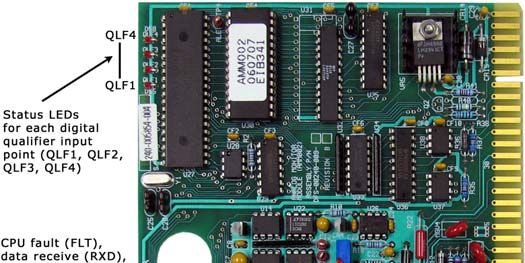
Table of Contents

Figure 28: Analog Monitor Point Wiring (0-20 mA Current with Transducer Supplied Power)........................50
Figure 29: Analog Monitor Point Wiring (0-20 mA Current with AMM-supplied Power) .................................51
Figure 30: Analog Monitor Point Wiring (0-5 Volt)...................................................................................................51
Figure 31: Analog Control Point Wiring ......................................................................................................................52
Figure 32: Addressing Modules .....................................................................................................................................54
Figure 33: Modular Backplane (MBP001) Used in RTU204 ....................................................................................54
Figure 34: BEM Wiring (Standard Installation) ..........................................................................................................55
Figure 35: BEM Wiring (TCU Installation) .................................................................................................................56
Figure 36: Solar Power Module Wiring ........................................................................................................................57

                                                                                 iv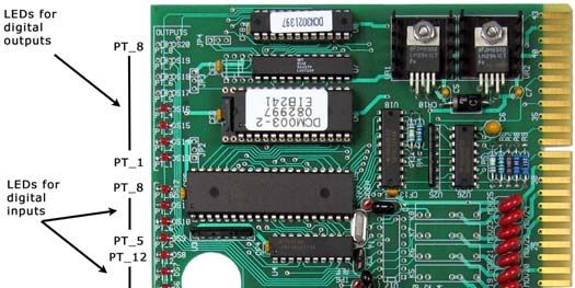
Chapter 1: TAC II SCADA System Overview

Purpose of This Guide
This guide outlines the planning considerations and installation techniques required for proper
installation of a TAC II SCADA System. Additionally, it provides information that is helpful when
initially planning and configuring a SCADA system.
The intended audience is DFS installation teams, DFS Authorized VARs, Engineering Firms and
established DFS customers. This guide assumes the reader is an experienced electrical technician, who
has similar systems or instrumentation experience and is familiar with electrical codes and safety
procedures.
This text is not all inclusive of the products and services offered by DFS. The evolving needs of our
customers and the creative nature of Data Flow Systems’ engineering group ensure there is a continuous
stream of solutions and products that may not be documented herein.
You can find brochures, technical specifications, and installation and operation manuals for Data Flow
Systems’ hardware and software products on our website (www.DataFlowSys.com).
Note: This manual references HT3 – the latest version of Data Flow Systems' SCADA software.
However, most of the information also applies to HyperTAC II. Differences will be noted where they
occur.

SCADA System
EPA and other government regulations have
mandated that public utilities provide ever-
increasing oversight of their systems. Utility
departments are learning that a good SCADA
system -- the technology of automatic
transmission of data from a remote source to
a receiving station for recording and analysis
-- can provide the backbone for remotely
monitoring and controlling their equipment
and services.
Because a utility’s stations are typically
spread throughout a district, city, or county,
SCADA systems are the most reliable and
cost effective means to tie each of the remote
locations back to the plant. When using radio,
the system utilizes a common FCC licensed
frequency, master radio and a central server
with HMI computer(s). The server queries

                                                  -1-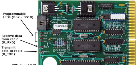
TAC II Installation Planning Guide
each of the remote locations for the status of pumps, valves, pressures, etc. The system can also provide
remote control as well as local automation of each of those components and incorporate process
automation functions.
The SCADA server polls each remote location (Remote Terminal Unit - RTU) for information. To do
this, each RTU has a unique address so it knows when to respond. The total poll loop time is dependent
on the number of remote sites within the system as well as the number of changes that occurred since the
last response.
The TAC II SCADA System
A typical DFS TAC II SCADA System
starts with the central site equipment, usually
located at a treatment plant or main office.
The equipment at the central site usually
includes a SCADA master (CTU) with radio
transceiver, a communications tower with
antenna, a Hyper SCADA Server (HSS), and
at least one HMI computer. Options for
using Ethernet and cellular to communicate
with remote sites are also available.
Remote Terminal Units (RTU) are located at
the well-fields, lift stations, pump stations,
treatment plants, reuse ponds, storage tanks,
and other various operations scattered
throughout a utility’s service area and plants. Figure 1: Typical TAC II SCADA System
I/O modules in the RTU are wired to the
equipment that the utility wants to monitor
and control.
The Hyper SCADA Server (HSS) controls the RTU polling sequence, collects data from remotes using
radio, Ethernet network, and cellular network sources, stores the data in a MySQL database, and hosts
the HT3 SCADA Software. The HSS makes the data available to users on the local network and to the
Internet through a firewall.
The SCADA Master (CTU) communicates with most remotes directly. When that isn’t possible, two
options are available:
A Forwarding Terminal Unit (FTU), aka “repeater,” can extend the CTU’s range to include a cluster
of RTUs or utilize a tall antenna mounting location.
A technique called digipeating, aka “store and forward,” can be used to add one or two distant
stations using an existing RTU to bridge the gap.
We designed the HT3 SCADA Software specifically for use by water and wastewater utilities. All of its
features, functions, and reporting tools are the result of specific needs and recommendations received
from our customers.
Data Flow Systems’ goal was to build a total solution package designed specifically for the utility to
easily operate, maintain, and expand. Each system is a mix of standardized, off-the-shelf components
-2-TAC II SCADA System Overview
configured to support the unique applications of each customer. We tailor the design to maintain a highly
efficient, reliable, and cost-effective system.
TAC II Communications
The TAC II SCADA System offers multiple communication methods and protocols. DFS analyzes each
utility’s application to determine which implementation best suits their requirements.
The system transmits message information to the Hyper SCADA Server. This information is analyzed for
alarm conditions, used to update instructions to other sites, and stored for use in detailed reports. Every
transition of an I/O (input/output) point in the system is logged in the database, permitting the user to
create reports and trends for any point in the system.
Communication Methods
The central site can communicate with remotes using radio, Ethernet, or cellular.
Radio
When radio communication is used, DFS’ primary goal is to establish a direct radio link between the
CTU and RTU. Our system employs an ingenious technique called “Continuous Differential Polling.”
Continuous Differential Polling is a time-division-multiplexed radio network that supports poll by
exception and sequential global polling (multiple RTUs responding in sequence to a single poll). RTU
messages incorporate time-tagging to provide a minimum time accuracy of +/- 2 seconds of the actual
change at the RTU.
DFS exclusively uses FCC Licensed Frequencies in the VHF and UHF bands for their performance
characteristics and licensing protections. We do not recommend the use of licensed/unlicensed 900
MHz frequencies or 2.4/5.8 GHz spread spectrum for SCADA communications.
The area of coverage varies due to terrain, antenna height, frequency band, and foliage. Data Flow
Systems will provide a radio-link budget survey for your specific sites and locations to determine
antenna height requirements. Chapter 4 has additional information on frequencies and licensing.
Radio RTUs come installed with either a Radio Interface Module (RIM) or Telemetry Interface
Module (TIM).
Radio Interface Module (RIM006-X) – The RIM incorporates an FM digital synthesized radio
transceiver programmed to a customer-specific FCC licensed frequency. The RIM006 controls
the radio during the polling sequence. All communications are in ASCII and utilize an error
detecting data transfer protocol. The RIM006 features a service port that provides
communications link monitoring locally. The service port also provides the capability to directly
monitor and/or control each I/O module in its RTU.
Telemetry Interface Module (TIM007) - The TIM is a microprocessor-controlled module with
an integrated serial digital radio. The TIM is programmed to a customer-specific FCC licensed
frequency. A data buffer on the TIM enables it to query its modules for status between radio
polling loops and store that information until it is requested from the central site – a particularly
-3-TAC II Installation Planning Guide
useful feature for sites with long radio polling loops. The TIM also features a wake up / report /
sleep mode that aids in battery conservation in solar-powered applications.
Both the RIM and the TIM can interface with up to 15 I/O modules of any combination.
Both modules also support four levels of digipeating (store and forward). Digipeating enables the
radio signal from a distant RTU to be routed to the central site by passing its message through up to
three RTUs. This is a powerful option for RTU locations that that require short antenna heights or
those with distance or terrain challenges. Through this technique, the system can support a small
number of remote stations outside the main coverage area without the utility having to acquire a
second frequency or a repeater.
The DFS TAC II SCADA System as a whole can accommodate up to (505) RIMs or TIMs per
communications link.
Ethernet
The SCADA System offers a means to communicate with RTUs over an Ethernet network
connection. An RTU utilizing network for communications will incorporate the appropriate network
appliance such as fiber media converter or Ethernet switch. 10 Mbps and 10/100 Mbps network
speeds are supported, as well as multi-mode and single mode fiber optic connections. Fiber-based
network communication is ideal when RTUs are located throughout a treatment plant.
Cellular
DFS offers a cellular RTU option for areas where a conventional radio-based SCADA system is not a
viable option for monitoring remote sites. Instead of a radio, the RTU uses a Verizon cellular modem
for communication. Using cellular networks and the Internet, the cellular RTU is able to provide
around-the-clock delivery of data and information about your equipment.
Cellular RTUs use a pop-up scheme where the HSS operates as a “listener” via a special driver (Net
DFP). Instead of polling the remotes, the HSS waits for messages from them. Each remote (Cellular
RTU) stores status changes locally in an event table until one of four configured events occur. When
an event occurs, the remote transmits information from the event table to the HSS, empties the event
table, and begins accumulating event data again.
Communication Protocols
Our own highly efficient TAC II protocol provides time-tagging accuracy of two (2) seconds for changes
in status occurring at each remote site. This level of accuracy is very important when dealing with how
long a pump has run, or to determine exactly when a valve opened or an alarm condition occurred.
TAC II protocol maximizes data collection efficiency by only sending information that has changed.
Once the driver in HT3 has obtained the status of a station it will begin to poll it for changes as opposed
to requesting full status. For added efficiency the driver will poll groups of stations configured
consecutively (up to 12) for changes.
With our Derivative Fractional Protocol (DFP), HT3 doesn’t send change/no change queries to remotes,
but instead polls them for table information. In this mode, the overhead of asking for changes and then
polling for status is eliminated. Stations equipped with appropriate Telemetry Interface Modules (TIMs)
-4-TAC II SCADA System Overview
or Telemetry Control Modules (TCUs) can use DFP. DFP also has a solar mode, which is used for all
solar powered sites.
A third communication protocol (NetDFP) is used for cellular stations. NetDFP is essentially a Modbus
driver with a special flag set in the HT3 registry that causes the driver to operate as a "listener." The
cellular RTUs communicate over the Verizon cellular network using a pop-up scheme.
Our HT3 SCADA Software also supports Modbus TCP/IP, Modbus RTU, and Modbus ASCII.
The Central Site and RTUs
The central site equipment consists of a Hyper SCADA Server, Central Terminal Unit (for radio
communication), and one or more HMI (human-machine interface) computers.
Hyper SCADA Server
The Hyper SCADA Server (HSS) is a self-
contained, modularized, SCADA Server that is
packaged in a protective wall-mounted enclosure.
The HSS controls the RTU polling sequence,
collects and stores data, and hosts the HT3
SCADA Software for all available user access
methods (e.g., computer workstations on the local
network, smart phones over the Internet). The
Hyper SCADA Server couples the power of
networking with the stability and versatility of the
Linux Operating System and MySQL to offer a
SCADA System Server that is secure, fast, and
reliable.
The Hyper SCADA Server includes all of the
necessary software required to implement a fully
operational SCADA System right out of the box. It
includes DFS' HT3 SCADA Software Program,
Browser-based Client HMI Software, a virtually
unlimited number of Development Client Licenses,
Alarm, Report and Trending Software, Process
Logic Building Software, Graphical Screen
Building Tools, Historical Database and MySQL.
We designed the HT3 SCADA Software
specifically for use by water and wastewater
utilities. All of its features, functions, and reporting
tools are the result of specific needs and
recommendations received from our customers.
-5-TAC II Installation Planning Guide
A fiber optic connection is established to communicate with the master radio (where applicable). Also
connected are printers, LAN networks, remote terminals, and any other computer equipment and
software required to support the utility’s SCADA requirements.
For cellular operation, the HSS must have a static IP address and be available on the Internet. When your
HSS is installed by DFS, it will be configured with the firewall modified to open a specific port. This is
the port the HSS will be “listening” on for messages from the Cellular RTUs.
The system can be partitioned so the fresh water, wastewater, and/or collections departments can
simulate having their own system. This, in effect, allows the utility to operate separate systems on the
same frequency using the same central site equipment.
It is important to note that the operation of the utility’s equipment at the remote sites is not directly
dependent on the system. The utility’s equipment at a remote site will continue to operate in the event of
a communications or central site failure. Naturally, data logging and alarm annunciation are limited
during these types of failures.
Equipment operations at critical, but isolated, remote sites can also be controlled by installing
“intelligent” PLC modules at the site. These modules contain preprogrammed logic and firmware
instructions or parameters written to the customer’s specification. During normal operations, the
parameters (set points) can be changed or updated remotely by the SCADA system over the
communications link and locally at the PLC.
System Access
Operator Workstations
Operator workstations (HMI computers) access the
system over the local network and the Internet. Our
HMI is browser based and provides easy access to the
SCADA system. Multiple users can simultaneously
monitor, control, view alarms, and run reports and
trends.
HT3 Mobile
A mobile version of HT3 optimized for today's smart phones is available as an upgrade to your
system. In HT3 Mobile, users will find all the essential tools needed for working in the field.
Remote Maintenance and Dial-In Access (411)
The Hyper SCADA Server contains a dedicated maintenance modem. DFS service personnel can
remotely access the utility’s system for maintenance and trouble shooting. This is a powerful and
responsive tool to help the utility diagnose problems and train operators. Additionally, we can easily
download SCADA software updates (always free), and modify or correct equipment configurations
over the maintenance modem.
This modem can also be used by the utility to call into the system and query the system for status
and/or initiate control commands using the phones keypad. This feature is extremely powerful when
used in conjunction with a cellular phone and a laptop computer. If desired, utility personnel can
-6-TAC II SCADA System Overview
monitor and operate their entire system from home, or from a remote field location. This is an
excellent option for utilities short on personnel.
Alarm Dial-Out (911)
If an alarm signal from a remote site is not acknowledged at the Central Site, the system will begin
calling a customer configured phone list.
Once someone answers the phone, the system will ask for an authentication code before announcing
the alarm condition. The system will continue to dial down the list until it gets a correct code
response. The functionality of this feature is completely configurable by the user. The system records
all voice unit activity in the system log.
Telephone Lines (for dial in and dial out features)
We recommend the use of two (2) separate telephone lines at the Hyper SCADA Server location for
independent use of the 411 and 911 features. At a minimum, one telephone line is required for
warranty purposes.
Central Terminal Unit (Master Radio)
The Central Terminal Unit (CTU) houses the master radio and communicates with the RTUs. Fiber optic
cable connects the CTU to the Hyper SCADA Server while providing electrical isolation for protection
from surge and lightning damage. The CTU is typically mounted on the central site communications
tower.
DFS designs the radio system specific to your required coverage area. The CTU antenna tower height is
dictated by the radio communications study. The central antenna is typically a high gain, omni-
directional antenna selected specifically for the frequency of operation.
The data transmission connection between the Hyper SCADA Server and the CTU is by fiber optic
cable. DFS incorporated optical fiber connections as its standard in order to isolate the server from high
voltage spikes induced by nearby lightning strikes. This network connectivity also provides for another
design tool in the system architecture, as there is no requirement for the HSS to be co-located with the
CTU and tower.
The radio and power supply modules used at the CTU and RTUs are the same, and are interchangeable
throughout the system. This provides for increased redundancy, and reduces the spare parts requirements.
Forwarding Terminal Unit (FTU)
The FTU provides a means to establish communications to a network of RTUs that are distant from the
master radio or are otherwise unable to communicate due to terrain. The FTU is similar to a repeater and
incorporates two radios.
The FTU utilizes one frequency for receiving and transmitting communications with the master radio,
and another frequency for communicating with the RTUs. This difference permits RTUs to act as
digipeaters since they receive and transmit on the same frequency. Continuous Differential Polling is
utilized and RTU messaging incorporates the same +/- 2 seconds time-tagging accuracy as the standard
system.
-7-TAC II Installation Planning Guide
The Remote Terminal Unit (RTU)
Remote Terminal Units (RTU) are located at the well-fields, lift stations,
pump stations, treatment plants, reuse ponds, storage tanks, and other
various operations scattered throughout a utility’s service area and plants.
I/O modules in the RTU are wired to the equipment that the utility wants
to monitor and control. RTUs can communicate with the central site
using radio, Ethernet network, or cellular network.
Radio-based RTU
Most radio-based RTU installations incorporate an Enclosure, Tower
Assembly, and Yagi Antenna. Shown at right is an example of a
typical assembly.
The antenna shown is a high gain Yagi.
The mast is a 21 foot galvanized 1¼” pipe and the tower is a
Rohn top section encased in a concrete foundation.
DFS has several RTU antenna tower configurations, including
assemblies certified to meet various wind load requirements.
The RTU is “wired” into the motor control circuits and signaling
circuits within the station’s control panel. It communicates with the
central site via a two-way radio link. The central sequentially polls
each RTU to receive status from, or transmit instructions to, the
attached equipment. The total poll loop time is dependent on the
number of remote sites within the system as well as the number of
changes that occurred since the last response.
Ethernet-based RTU
This is typically used in an in-plant RTU that would other wise require a “rubber duck” antenna.
Using a network interface module in place of a RIM and antenna greatly reduces polling time.
Each RTU station contains a network module - either a NIM (Network Interface Module) or a FIM
(Fiber Interface Module) that is installed in the Radio Interface Module (RIM) slot of the RTU. The
network module in each RTU transfers information between the Hyper SCADA Server and its
resident modules. No connector changes are necessary; the FIM and the RIM are keyed the same.
Communication between the HSS and the RTU’s function modules takes place over a network via a
NIM driver; the Network RTUs and the HSS must be on the same local area network.
The FIM supports both 9600 and 1200 bps modules. To obtain the most efficient polling rate, we
recommend that 9600-baud modules be used.
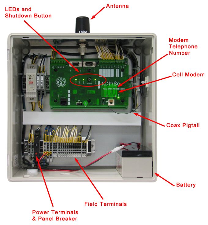
Cellular-based RTU (RDP180-C)
A Cellular SCADA System is particularly useful for a utility or company with an extended service
area where a conventional radio-based SCADA system is not a viable option for monitoring remote
-8-TAC II SCADA System Overview
sites. Instead of a radio, the RDP180-C RTU comes installed with an RDP180 (a rail-mounted PLC)
that uses a Verizon cellular modem for communication.
The RDP180-C features a NEMA 4X-rated, non-metallic enclosure, RDP180, power supply (includes
10A breaker), 1.2Ah backup battery, and cellular antenna. The RDP180 provides nine (9) discrete
inputs (interposing relay), two (2) discrete outputs (dry contact), and one (1) analog input (0-5VDC or
4-20A) as local I/O. (I/O expansion is possible with the installation of additional equipment.)
Each Cellular RTU provides time stamped status of selected data point that is accurate to the second.
This I/O as well as built-in Special Function Registers, which include such things as cell signal
strength and power supply voltage, can be configured to report changes in status to the HSS.
A cellular RTU requires a Verizon data plan, Hyper SCADA Server with HT3 3.1.1 or newer
installed, and a Hyper SCADA Server with a static IP address that is accessible via the Internet
RTU Enclosures
DFS fabricates its RTU enclosures from high-grade stainless steel. They are “rain tight,” “weatherproof,”
and can be installed in “damp and wet locations” as defined in the National Electrical Code (NEC).
The white painted exterior is not to protect the metal; rather, its purpose is to help keep the interior cooler
by reflecting heat.
All fittings, mounts, brackets, latches, nuts and bolts used in fabricating and mounting the enclosure are
stainless steel. All other components are hot-dipped galvanized or otherwise certified for outdoor and
electrical use.
The size of an RTU enclosure is determined by the number of active modules required for the
application. Each RTU contains a power supply module, a radio or network module, and up to 2, 4, 10,
or 15 input/output modules. Each module is a separate, plug-in, functional unit that makes service and
repair very easy and eliminates the need for tools.
The 200 Series RTU Modular Backplane
The plug-in function modules used in the 200 Series RTUs are plugged into card edge connectors
mounted on a passive Modular Backplane (MBP). The MBP is a printed circuit board composed of card
edge connectors for the modules, module bus circuitry, and a connection for the back-up battery.
The MBP bolts into the RTU enclosure, serving as both a motherboard and backplate onto which the
active modules are plugged. Wiring connections made to terminals are permanently soldered on the
backplane - meaning, the plug-in module can be removed from the MBP without disturbing the wiring or
requiring the use of tools. There are no active components permanently mounted to it, making it highly
reliable. (See photo on next page.)
-9-TAC II Installation Planning Guide
Figure 2: Modular Backplane
Figure 3: Modular Backplane Installed in 200 Series RTU
- 10 -Chapter 2: Function Modules and PLC Devices
Overview
Each function module and PLC device is a separate, self-contained device. All of the modules listed
below except the Telemetry Control Unit (TCU) and the Rail Data Processor (RDP180) are plug-in
function modules.
The plug-in function modules are designed to be installed in a slot of the Modular Backplane (MBP).
This design allows them to be removed without disturbing field wiring. The base of each function
module is a 5”x 7” printed circuit board (PCB). The PCB contains all of the hardware and firmware
required to provide the specific functions for which we designed the module to perform.
The Telemetry Control Unit (TCU) is designed to be permanently installed in a panel using mounting
brackets supplied by DFS. The unit can be mounted flush to the back plate of the panel, stood off the
back plate, or mounted to a front panel. The TCU can be incorporated into a Remote Terminal Unit
(RTU) by using a Bus Extender Module (BEM). The RDP180-C is designed as a standard DIN-rail
mounted device.
All CTUs and 200 Series RTUs contain the Power Supply Module and a communications module (radio
or Ethernet). All other modules are dictated by the application, as their use depends on what equipment
the utility wants to monitor and/or control at the site.
Function modules can be mixed and matched as the application requires and in no particular order (ease
of expansion). Adding an I/O module to expand an existing RTU is as simple as plugging it in, wiring it
up, and updating the configuration in the SCADA Server.
The following types of function modules and PLC devices are available:
Communication and Power Supply Modules
Power Supply Module (PSM003-1)
Solar Power Module (SPM002)
Telemetry Interface Module (TIM007)
Radio Interface Module (RIM006-X)
Network Interface Module (NIM001 - ten different versions are available)
Bus Extender Module (BEM001)
Digital Modules
Modules with I/O points having only two states (e.g., On/Off, Open/Closed, etc.)
Digital Monitor Module (DMM002)
Digital Control Module (DCM003-X - 6 versions available) – Also features digital input
capabilities.
- 11 -TAC II Installation Planning Guide
Analog Modules
Modules with I/O points represented as a numerical value (e.g. pressure, level, etc.)
Analog Monitor Module (AMM002)
Analog Control Module (ACM002) – Also features digital input capabilities.
PLC Devices
Devices that perform complete, automatic control functions.
Programmable Logical Control Module (PLC001 and PLC033) – Both of these PLCs are
designed as plug-in function modules. They can monitor and control remote site equipment
locally on a stand-alone basis.
Telemetry Control Unit (TCU001) – Pump controller designed to automate the operation of
simplex, duplex and triplex sewer pumping stations. It is also customizable for Variable
Frequency Drive (VFD) applications.
Rail Data Processor (RDP180) – Rail-mounted PLC used in cellular RTUs.
What Can I Monitor and Control?
Deciding what the utility should monitor and control is one of the most important aspects of setting up a
SCADA system.
The function modules can monitor and control the following kinds of I/O (input/output) points and
signals within the utility’s system.
Digital Inputs
Digital inputs (DI) monitor a voltage/no voltage condition. Examples of DI monitoring points include:
pump runs and motor starter failures
commercial power loss
floats used to indicate high/low well levels
seal leaks
generator running status
valves open or closed
intrusion alarms
any other equipment or device whose operation opens or closes a circuit
Digital Outputs
Digital outputs (DO) can be used to control relays, actuators, motor starters, solenoid valves, etc.
Examples of DO control points include:
energize a relay
activate or turn-off a motor starter circuit
turn-on or off a remote generator
open or close a valve
- 12 -Function Modules and PLC Devices
Analog Inputs
Analog inputs (AI) monitor devices that have an output of 0-5 VDC, or 0-20 mA. The Analog Monitor
Module incorporates an isolated 24 VDC loop power source for each analog input point. Examples of AI
monitoring points include:
measuring pressure
measuring flow
measuring level
measuring VFD speeds
monitoring chemical analyzers
Analog Outputs
Analog outputs (AO) control devices that require 0-20 mA. The Analog Control Module incorporates an
isolated 24 VDC loop power source for each analog output point. Examples of AO control points
include:
control a throttle valve
control quantity of chemical injections
control gates
control VFD speeds
display level or flow measured at a different location
Using the Information
Once the module’s signals are transmitted to the central site, the SCADA system can do several things:
Analyze the information to see if it matches pre-set alarm conditions, e.g., a loss-of-commercial-
power alarm followed by a high-well alarm means send out the generator truck!
Log the information into the history files used to produce management reports, e.g., a day-by-day
report of run times by each pump at each site; or derived flow reports.
Using a mixture of function modules, any remote site can be configured to perform a broad range of
digital and analog monitoring and control operations.
The following are additional considerations when planning the monitoring of I/O points:
Do not focus on just monitoring alarm lights and bells. Instead, monitor the actual conditions that
could cause the alarms to activate.
A lot of information can be gathered just by analyzing pump run times rather than adding extra
analog values such as amperage, head pressure or flow rate.
Monitoring points that give you warnings of failure (e.g., sump floats, commercial power feeds, etc.)
are imperative for timely responses to potentially damaging events.
- 13 -TAC II Installation Planning Guide
Descriptions of Function Modules and PLC Devices
The following pages contain descriptions of the functions and capabilities of DFS’ function modules. Cut
sheets and specifications are available on our web site: www.DataFlowSys.com.
Figure 4: Printed Circuit Board
The following features are common to all of our function modules:
Opto-isolated inputs and outputs.
LEDs to indicate operating statuses and help with system diagnostics.
Protective coatings on the circuit boards to help prevent corrosion.
Each module is uniquely keyed. The card edge connectors are keyed to correspond with the assigned
module to prevent inserting the wrong module into the connector.
Gold edge connector fingers on the modules to ensure positive contact when plugged into the card
edge connector mounted on the modular backplane.
Non-destructive surge protection. Three-year warranty including lightning damage.
No adjustments, switches, or straps. Modules are self-configuring.
On-board communications and functional firmware.
- 14 -You can also read