Two-dimensional and surface backscattering Mueller matrices of anisotropic sphere-cylinder scattering media: a quantitative study of influence ...
←
→
Page content transcription
If your browser does not render page correctly, please read the page content below
Two-dimensional and surface
                 backscattering Mueller matrices of
                 anisotropic sphere-cylinder scattering
                 media: a quantitative study of influence
                 from fibrous scatterers

                 Honghui He
                 Nan Zeng
                 E. Du
                 Yihong Guo
                 Dongzhi Li
                 Ran Liao
                 Yonghong He
                 Hui Ma

Downloaded From: https://www.spiedigitallibrary.org/journals/Journal-of-Biomedical-Optics on 27 Jun 2022
Terms of Use: https://www.spiedigitallibrary.org/terms-of-use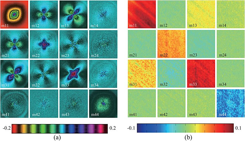
Journal of Biomedical Optics 18(4), 046002 (April 2013)

                Two-dimensional and surface backscattering Mueller
                matrices of anisotropic sphere-cylinder scattering media:
                a quantitative study of influence from fibrous scatterers
                Honghui He,a Nan Zeng,a E. Du,a,b Yihong Guo,a,b Dongzhi Li,a,b Ran Liao,a Yonghong He,a and Hui Maa,b
                a
                    Tsinghua University, Graduate School at Shenzhen, Shenzhen Key Laboratory for Minimal Invasive Medical Technologies, Shenzhen 518055, China
                b
                    Tsinghua University, Department of Physics, Beijing 100084, China

                               Abstract. We present both the two-dimensional backscattering point-illumination and surface-illumination Mueller
                               matrices for the anisotropic sphere-cylinder scattering media. The experimental results of the microsphere-silk sam-
                               ple show that the Mueller matrix elements of an anisotropic scattering medium are different from those of an iso-
                               tropic medium. Moreover, both the experiments and Monte Carlo simulations show that the directions of the fibrous
                               scatterers have prominent effects on the Mueller matrix elements. As the fibrous samples rotate, the surface-illu-
                               mination Mueller matrix measurement results for the m12, m21, m13, m31, m22, m23, m32, and m33 elements
                               represent periodical variations. Experiments on skeletal muscle and porcine liver tissue samples confirm that the
                               periodical changes for the surface-illumination Mueller matrix elements are closely related to the well aligned
                               fibrous scatterers. The m22, m23, m32, and m33 elements are powerful tools for quantitative characterization
                               of anisotropic scattering media, including biological tissues. © 2013 Society of Photo-Optical Instrumentation Engineers (SPIE)
                               [DOI: 10.1117/1.JBO.18.4.046002]

                               Keywords: Mueller matrix; scattering; polarization; tissue; anisotropy.
                               Paper 12807R received Dec. 19, 2012; revised manuscript received Mar. 11, 2013; accepted for publication Mar. 14, 2013; published
                               online Apr. 1, 2013; corrected Apr. 4, 2013.

                1      Introduction                                                                the complicated interactions between photons and the aniso-
                Polarization measurement is a powerful tool to probe the fun-                      tropic biological tissues, and to extract the structural information
                damental interactions between photons and media. To describe                       of the sample. In previous studies we have used the sphere-cyl-
                the polarization states of photons and the properties of media,                    inder scattering model (SCSM) to explain the polarized optical
                                                                                                   properties of biological tissues, including skeletal muscles.23–26
                different representations have been established. For turbid
                                                                                                   On the other hand, we have demonstrated that the Mueller
                media, the Stokes vector–Mueller matrix method is applicable
                                                                                                   matrix can be used to characterize the properties of a sphere-
                because of its capability for quantitatively describing the behav-
                                                                                                   cylinder scattering medium.10 In this paper, we measure and
                iors of both the completely polarized and partially depolarized
                                                                                                   compare both the 2-D backscattering Mueller matrix patterns
                scattered photons.1 It has been demonstrated in previous publi-
                                                                                                   and the surface-illumination Mueller matrix for the anisotropic
                cations, that for an isotropic medium, one may obtain the density
                                                                                                   sphere-cylinder scattering media. We examine in detail the
                and sizes of the scatterers from the two-dimensional (2-D)
                                                                                                   characteristic features in each Mueller matrix element and the
                patterns of backscattering Mueller matrix when the illumination
                                                                                                   influence of the fibrous scatterers on the Mueller matrix.
                spot is much smaller than the imaging area.2–4 However, for light
                                                                                                   Moreover, the experimental and Monte Carlo simulated results
                scattering in more complicated anisotropic turbid media,5–9 it is
                                                                                                   show that the Mueller matrix elements can be used to character-
                not trivial to carry out such a quantitative analysis of the Mueller
                                                                                                   ize the structural properties of some anisotropic biological tis-
                matrix elements. Each element may correlate to different proper-
                                                                                                   sues. Combined with other quantitative techniques, such as
                ties of the media, making it difficult to find explicit relations
                                                                                                   polar decomposition and rotating linear polarization imaging
                between the two.10 Thus, there have been strong motivations                        (RLPI),13,25 the Mueller matrix and SCSM can be used as poten-
                to interpret the physics insights hidden within the Mueller                        tially powerful tools in biomedical applications including patho-
                matrix. Recently, a method called polar decomposition of                           logical diagnosis.
                Mueller matrix has been developed to separate different contri-
                butions by scattering, retardation and dichroism,11 and tested in
                biomedical applications.12–20                                                      2       Materials and Methods
                    Most biological tissues contain structurally anisotropic com-
                ponents, such as the myofibrils in skeletal muscles, the collagen                  2.1      Experimental Setup
                fibers in tendons, and axon.21,22 For the studies of biomedical
                optics and its applications in therapeutics and diagnostics,                       In this paper, two types of experimental setups are used; one is a
                one needs to use properly simplified models to understand                          typical configuration for 2-D backscattering Mueller matrix pat-
                                                                                                   tern measurements, as shown in Fig. 1(a).27,28 The light source is
                                                                                                   a 633-nm linearly polarized He-Ne laser. The polarization states
                Address all correspondence to: Hui Ma, Tsinghua University, Graduate School at     of the incident light are controlled by a set of a quarter-wave
                Shenzhen, Shenzhen Key Laboratory for Minimal Invasive Medical Technologies,
                Shenzhen 518055, China. Tel: 86-755-26036238; Fax: 86-755-26036238;
                E-mail: mahui@tsinghua.edu.cn                                                      0091-3286/2013/$25.00 © 2013 SPIE

                Journal of Biomedical Optics                                                046002-1                                            April 2013   •   Vol. 18(4)

Downloaded From: https://www.spiedigitallibrary.org/journals/Journal-of-Biomedical-Optics on 27 Jun 2022
Terms of Use: https://www.spiedigitallibrary.org/terms-of-use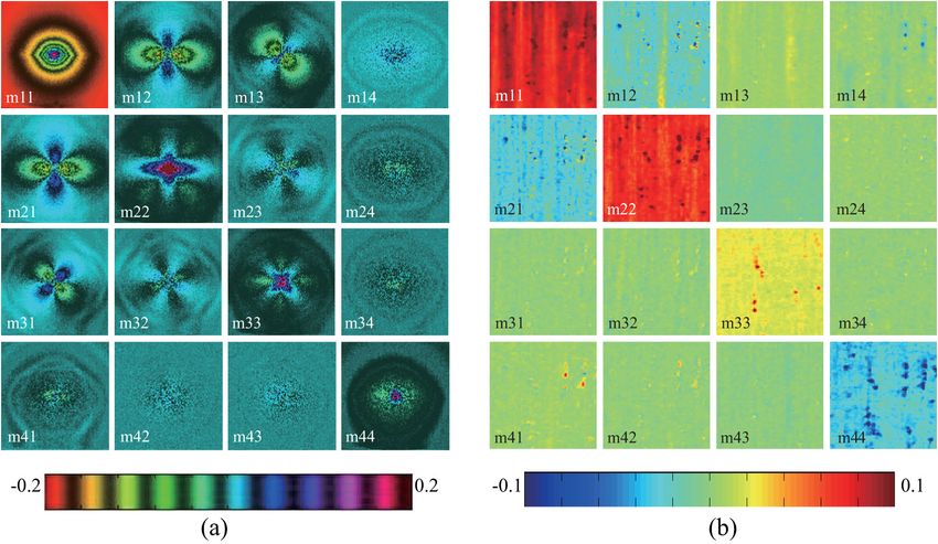
He et al.: Two-dimensional and surface backscattering Mueller matrices of anisotropic sphere-cylinder scattering media. . .

                                                                                                   set of a quarter-wave plate (QW2) and linear polarizer (P2).
                                                                                                   Then the backscattering photons are steered to and recorded
                                                                                                   by a 14-bit CCD camera to produce the reflectance images
                                                                                                   of the samples. In this part of experiments, the illumination
                                                                                                   area from the He-Ne laser is confined to a 1-mm spot, which
                                                                                                   is much smaller than the imaging area (1.5 × 1.5 cm). Then,
                                                                                                   we can obtain the patterns of the backscattering Mueller matrix
                                                                                                   elements for a turbid medium.
                                                                                                       The other experimental setup used in this paper is for surface-
                                                                                                   illumination Mueller matrix measurement, as shown in
                                                                                                   Fig. 1(b).29–34 Compared to Fig. 1(a), the main difference of
                                                                                                   this configuration is the illumination method. The diameter
                Fig. 1 Schematics of the experimental setups. P: polarizer; QW: quar-              of the illumination area for Fig. 1(b) is about 2 cm, which is
                ter-wave plate; L: lens. (a) Setup for the 2-D backscattering Mueller
                                                                                                   larger than the sample or the imaging area (1.5 × 1.5 cm).
                matrix pattern measurement. The diameter of the illumination area
                from the He-Ne laser is about 1 mm, which is smaller than the imaging              Therefore, the scattering patterns are smoothed out in the surface
                area (about 1.5 × 1.5 cm). (b) Setup for the surface-illumination Mueller          backscattering Mueller matrix. Instead, the intensity matrix ele-
                matrix measurement. The polarized light illuminates the sample at                  ments for the samples are obtained. To eliminate the reflection
                about 30 deg angle to the normal to minimize the surface reflection                from the sample’s surface, the polarized light from a 1 W light
                effects. The diameter of the illumination area from the LED is about
                2 cm, which is larger than the imaging area (about 1.5 × 1.5 cm).
                                                                                                   emitting diode (LED) illuminates the sample at about a 30-deg
                                                                                                   angle to the normal. For measuring the 4 × 4 Mueller matrix, six
                plate (QW1) and a linear polarizer (P1). A mirror with a front                     polarization states for the incident light are achieved, i.e., hori-
                surface tilted at a 45-deg angle to the normal is positioned in                    zontal linear (H), vertical linear (V), 45-deg linear (P), 135-deg
                front of the sample. The incident light reaches the sample                         linear (M), left circular (L), and right circular (R), then, six
                through a 5-mm hole at the center of the mirror. Reflection                        polarization components corresponding to each incident state
                from the sample surface is directed to pass through the same                       are measured. After a total of 36 measurements are conducted,
                hole to minimize its interference to the back reflected light.                     the Mueller matrix of a turbid scattering medium can be calcu-
                The reflection polarization states are controlled by a second                      lated as Eq. (1):

                       0 m11       m12      m13      m14 1
                  B m21            m22      m23      m24 C
                M¼@                                      A
                    m31            m32      m33      m34
                    m41            m42      m43      m44
                   0 HH þ HV þ VH þ VV                                                                                                                                 (1)
                                                               HH þ HV − VH − VV                PH þ PV − MP − MM             RH þ RV − LH − LV 1
                     1 B HH − HV þ VH − VV                     HH − HV − VH þ VV                PH − PV − MH þ MV             RH − RV − LH þ LV C
                    ¼ @                                                                                                                         A:
                     2 HP − HM þ VP − VM                       HP − HM − VP þ VM                PP − PM − MP þ MM             RP − RM − LP þ LM
                         HR − LL þ VR − RL                     HR − VR þ VL − HL                PR − MR þ ML − PL             RR − RL − LR þ LL

                2.2     Sample and Monte Carlo Program                                             of infinitely long cylindrical and spherical scatterers embedded
                                                                                                   in a surrounding medium. In this paper, we use the simple
                In this paper, a microsphere-silk sample for the SCSM is                           SCSM, which consists of single dispersed spheres and cylinders
                designed and measured. It is a 5 × 2.8 × 2 cm cube consisting                      immersed in an isotropic medium. The parameters used in the
                of three layers.10 The first and third layers are solutions of poly-               Monte Carlo simulations are set to be the same as the experi-
                styrene microsphere (International Laboratory, USA), and the                       ments. The diameters of spherical and cylindrical scatterers
                second layer is a 3-mm thickness slab of well-aligned silk fibers.                 are 0.2 and 1.5 μm, respectively, and the refractive indices
                For the polystyrene microsphere solution, the diameter of the                      are 1.59 and 1.56, respectively. The refractive index of the sur-
                microsphere is 0.2 μm, and the total scattering coefficient of                     rounding medium is 1.33. The standard deviation of angular dis-
                the solution is 5 cm−1 . The parameters of the silk fiber layer                    tribution of the cylinders is 10 deg. The scattering coefficients of
                were determined in the previous study.24 The diameter of the                       the spherical and cylindrical scatterers are 5 and 70 cm−1 ,
                silk fiber is taken as 1.5 μm, and the refractive index is 1.56.                   respectively.
                The scattering coefficient of the silk layer is estimated as
                70 cm−1 . During the experiments, the direction of the silk
                layer has been adjusted to vary the anisotropy axis. To examine
                                                                                                   3       Results and Discussion
                the relationship between the Mueller matrix and the microscopic                    3.1      Experimental Results of Mueller Matrices for
                structure of the sample, the experimental results are compared to                           Sphere-Cylinder Scattering Samples
                Monte Carlo simulations based on the SCSM developed in our
                previous work.24 For the SCSM, the anisotropic and isotropic                       The experimental results of the backscattering Mueller matrices
                microstructures in the sample are approximated as a mixture                        for the sphere-cylinder scattering medium are shown in Fig. 2

                Journal of Biomedical Optics                                               046002-2                                             April 2013   •   Vol. 18(4)

Downloaded From: https://www.spiedigitallibrary.org/journals/Journal-of-Biomedical-Optics on 27 Jun 2022
Terms of Use: https://www.spiedigitallibrary.org/terms-of-use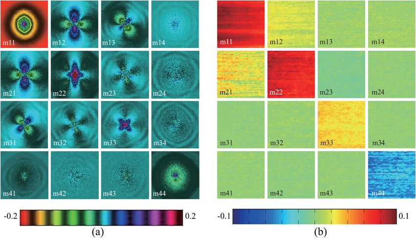
He et al.: Two-dimensional and surface backscattering Mueller matrices of anisotropic sphere-cylinder scattering media. . .

                Fig. 2 Experimental results of the backscattering Mueller matrices for the samples containing silk fibers and spheres. The silk fibers are along the y-axis
                direction: (a) 2-D backscattering Mueller matrix patterns; (b) intensity values for the surface-illumination Mueller matrix measurements. All the Mueller
                matrix elements are normalized by the m11 element. Please note that m11 uses its own colormap from 0 to 1, and the colormap for m22 and m33 in (b)
                is from −0.3 to 0.3.

                [Fig. 2(a) shows the 2-D backscattering Mueller matrix patterns,                   become lower than the m22 element. The m23 and m32 ele-
                and Fig. 2(b) shows the intensity for the surface-illumination                     ments have similar patterns. In the sphere-cylinder scattering
                Mueller matrix measurements]. In Fig. 2, the silk fibers are dis-                  medium, the intensity around the x axis is slightly larger
                tributed along the y-axis direction. Comparing to the Mueller                      than that in other parts. The m14, m41, m24, m42, m34, and
                matrix of an isotropic scattering medium (as shown in                              m43 elements in the isotropic medium with small spherical scat-
                Fig. 3), the characteristic features of the 2-D backscattering                     terers are blanks, but for the sphere-cylinder medium, these ele-
                Mueller matrix patterns for the SCSM can be summarized as                          ments may have some slight residue intensity along the x axis.
                follows: The m11 element for the isotropic medium is always                        The m44 elements for the isotropic and sphere-cylinder scatter-
                circular. However, for the sphere-cylinder scattering medium,                      ing media have circular patterns.
                the m11 is rhombic. The rhombic shape is a unique feature                              It should be pointed out that, for a sphere-cylinder scattering
                for the existence of anisotropic scattering.10                                     medium containing larger spherical scatterers, the 2-D Mueller
                    The m12 and m21 elements are quatrefoils for both the iso-                     matrix patterns are slightly different. For instance, the m24,
                tropic and sphere-cylinder scattering media, with negative value                   m42, m34, and m43 elements may have clearer patterns.
                around the x axis and positive value around the y axis. For the                    However, the main characteristic features are similar. For the
                isotropic medium, the intensity around the x axis is the same as                   sphere-cylinder scattering medium, the Mueller matrix patterns
                that around the y axis [Fig. 3(a)]. However, for the sphere-cyl-                   can be considered as the contributions from both the spherical
                inder medium with the cylinders along the y axis direction, the                    and cylindrical scatterers. According to the Mie scattering
                intensity around the x axis becomes higher. The m13 and m31                        theory for infinitely long cylinders, the photons tend to be scat-
                elements are also quatrefoils, with a 45-deg rotation to the m12                   tered to the perpendicular direction of cylindrical scatterers,1
                and m21 elements. For both the isotropic and anisotropic scat-                     i.e., the x axis in Fig. 2(a). Therefore, for most matrix elements
                tering media, the intensity distributions around the x and y axes                  in Fig. 2(a), the intensity distributions along the x axis are larger
                are the same. In an isotropic medium, the total intensities and                    than that in other parts. Using the property of the matrix ele-
                sizes of the m13 and m31 elements are nearly the same as the                       ments, the relative concentration of the cylindrical scatterers
                m12 and m21 elements, but for the anisotropic medium with y                        can be decided.
                axis direction cylinders, and the total intensities of the m13                         All the characteristic features for the 2-D patterns mentioned
                element, m31 becomes lower than the m12 and m21 elements.                          above can be used to detect the cylindrical scatterers in a turbid
                The m22 element has a cross-like pattern. For the isotropic                        media. However, the 2-D backscattering Mueller matrix patterns
                medium, the intensity distributions around x and y axes are                        can only be easily and clearly obtained for homogeneous scat-
                close. However, in the sphere-cylinder scattering medium, the                      tering media, such as the solutions with well-aligned fibers. For
                intensity around the x axis is higher than that around the y                       inhomogeneous media, the surface-illumination Mueller matrix
                axis. The m33 element always has a cross-like pattern, which                       measurements are more suitable. Since the illumination area is
                is similar to the m22 element with a 45-deg rotation, but the                      larger than the imaging area for the surface Mueller matrix mea-
                intensity distributions around the 45 deg- and 135-deg axes                        surements, the patterns as shown in Figs. 2(a) and 3(a) are no
                are close. In the sphere-cylinder medium with the fibrous scat-                    longer existed. What we get in the surface-illumination Mueller
                terers along the y axis, the total intensity of the m33 element                    matrix measurement is an intensity matrix, as shown in Fig. 2(b)

                Journal of Biomedical Optics                                               046002-3                                               April 2013   •   Vol. 18(4)

Downloaded From: https://www.spiedigitallibrary.org/journals/Journal-of-Biomedical-Optics on 27 Jun 2022
Terms of Use: https://www.spiedigitallibrary.org/terms-of-use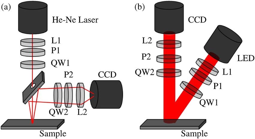
He et al.: Two-dimensional and surface backscattering Mueller matrices of anisotropic sphere-cylinder scattering media. . .

                Fig. 3 Experimental results of the backscattering Mueller matrices for the medium containing only 0.2-μm spherical scatterers: (a) 2-D backscattering
                Mueller matrix patterns; (b) intensity values for the surface-illumination Mueller matrix measurements. All Mueller matrix elements are normalized by
                m11. Please note that m11 uses its own colormap from 0 to 1, and the colormap for m22 and m33 in (b) is from −0.3 to 0.3.

                for the same microsphere-silk sample with the fibers along the y-                  respectively. Hence, the elongation of m11 can be used to decide
                axis direction. Comparing to the results of an isotropic scattering                the direction of the cylinders. According to the Mie scattering
                medium [Fig. 3(b)], the characteristic features for the sphere-                    theory, for the cylindrical scatterers along the x-axis direction,
                cylinder medium are different. For an isotropic medium                             photons tend to be scattered to y axis. Therefore, in Fig. 4(a), the
                [Fig. 3(b)], the Mueller matrix is diagonal, and the m12,                          positive parts for the m12 and m21 elements become prominent,
                m13, m14, m21, m23, m24, m31, m32, m34, m41, m42, and                              and the m22 becomes larger than the m33, with both patterns
                m43 elements are blanks. This is because that the quatrefoil pat-                  rotated by 90 deg as compared to Fig. 2(a). The elements in
                terns shown in Fig. 3(a) with both positive and negative parts                     the fourth row and fourth column have no clear patterns. For
                will be smoothed out when the illumination area is larger                          the cylindrical scatterers along the 45-deg-axis direction, pho-
                than the imaging plane. Moreover, the m22 and m33 elements                         tons tend to be scattered to the direction along the 135-deg
                are equal, and their values are positive. The values of the m22,                   axis. Hence, for the m13 and m31 elements with quatrefoil
                m33, and m44 elements are closely related to the particle sizes                    shapes in Fig. 5(a), the positive intensity around the 135-deg
                of isotropic media. As the diameter of the particles increases, the                axis is higher. The m12 and m21 elements are also quatrefoils,
                intensities of m22 and m33 decrease. However, for the sphere-                      whose total intensities and sizes become lower than the m13 and
                cylinder medium [as shown in Fig. 2(b)], the off-diagonal ele-                     m31 elements. Meanwhile, the m22 element still has a cross-like
                ments are no longer zeros, and the total intensity values for the                  pattern, but compared to Fig. 2(a), the intensity distributions
                m22 and m33 elements become different. For the sample con-                         around the x and y axes are getting much closer. The m33
                taining silk fibers along the y axis, m12 and m21 are negative.                    element becomes much larger than m22, and the intensity
                Moreover, the value for m22 is much larger than m33. These                         along the 135-deg axis is more prominent than those along
                intensity changes can be explained by using the 2-D backscat-                      other directions.F
                tering Mueller matrix patterns, as shown in Fig. 2(a). The cyl-                        Figures 4(b) and 5(b) show the surface-illumination Mueller
                inders along y axis results in more photons to be scattered to the                 matrix intensities for the samples, in which the silk fibers are
                x-axis direction; therefore, the negative parts become larger than                 along the y axis and 135-deg axes, respectively. It is clearly
                the positive parts for the m12 and m21 elements. Meanwhile, the                    shown that as the rotation of the silk fibers, the total values
                pattern of the m22 element becomes more prominent than the                         of m11, and the elements in the fourth row and fourth column
                m33 element, resulting in higher value of m22 than m33 in                          are not affected. However, the other elements represent periodi-
                Fig. 2(b).                                                                         cal intensity changes. For the sample with the silk layer along
                                                                                                   the 45-deg axis, the values of the m13 and m31 elements are
                3.2     Influence of Direction of the Fibers on the                                positive, while m12 and m21 are blanks (Fig. 6). What is
                        Mueller Matrices                                                           more, the value of the m22 becomes much smaller than that
                                                                                                   of the m33 element. Meanwhile, when the silk fibers are rotated
                To analyze the influence of the direction of the fibers on the                     to the x-axis or y-axis directions, the m12 and m21 elements
                Mueller matrix elements, we rotate the silk layer of the sample.                   become positive or negative, respectively, while the values of
                Figures 4(a) and 5(a) show the 2-D patterns for the samples with                   m13 and m31 become zeros. Moreover, the value of m22 is
                silks along the x- and 45-deg-axes directions, respectively.                       larger than m33. Such periodical variations do not exist in iso-
                Compared to Fig. 2(a), the elongation directions for the rhombic                   tropic media. Further analysis based on the experimental and
                m11 elements are changed to the y and 135-deg axes,                                Monte Carlo simulations show that the variation period for

                Journal of Biomedical Optics                                               046002-4                                             April 2013   •   Vol. 18(4)

Downloaded From: https://www.spiedigitallibrary.org/journals/Journal-of-Biomedical-Optics on 27 Jun 2022
Terms of Use: https://www.spiedigitallibrary.org/terms-of-use
He et al.: Two-dimensional and surface backscattering Mueller matrices of anisotropic sphere-cylinder scattering media. . .
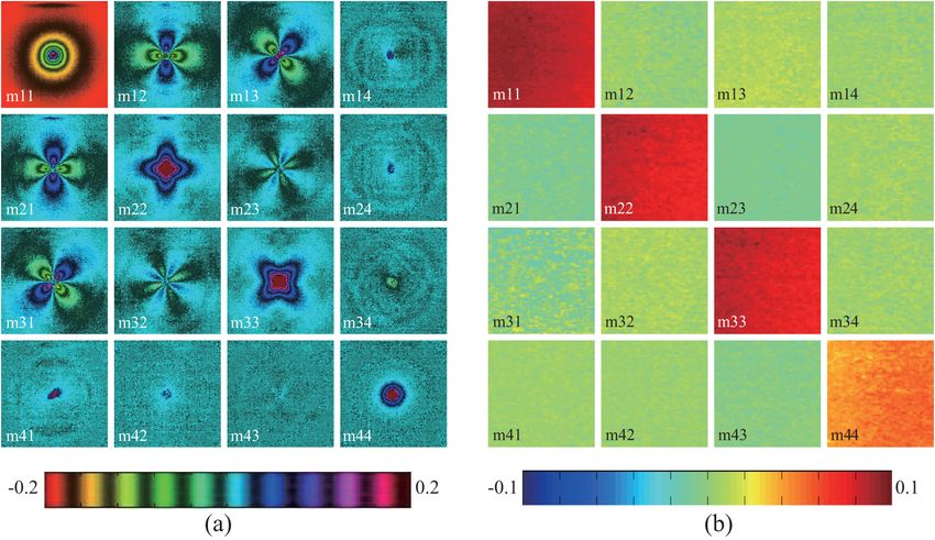
Fig. 4 Experimental results of the backscattering Mueller matrices for the sphere-cylinder scattering model (SCSM) medium. The silk fibers are along the
x-axis direction: (a) 2-D backscattering Mueller matrix patterns; (b) intensity values for the surface-illumination Mueller matrix measurements. All
Mueller matrix elements are normalized by m11. Please note that m11 uses its own colormap from 0 to 1, and the colormap for m22 and m33
in (b) is from −0.3 to 0.3.
Fig. 5 Experimental results of the backscattering Mueller matrices for the sphere-cylinder scattering model (SCSM) medium. The silk fibers are along the
45-deg axis direction: (a) 2-D backscattering Mueller matrix patterns; (b) intensity values for the surface-illumination Mueller matrix measurements.
Please note that m11 uses its own colormap from 0 to 1, and the colormap for m22 and m33 in (b) is from −0.3 to 0.3.
the m22, m23, m32, and m33 elements is π [as shown in Fig. 7 V) linear polarization states to H and V (or P and M) states.
(b), 7(c), 7(e), and 7(f)], while that for m12, m13, m21, and m31 The m22, m23, m32, and m33 elements have much larger ampli-
is 2π [as shown in Fig. 7(a) and 7(d)]. The m22 element rep- tudes than those for the m12, m13, m21, m31 elements. All
resents the ability for the medium to maintain horizontal (H) these intensity changes can be explained by using the 2-D
or vertical (V) linear polarization states at H or V polarized inci- Mueller matrix patterns and Mie scattering theory for infinitely
dence. The m33 element represents the ability to maintain 45- cylinders, as discussed above. It can also be observed in Fig. 7
deg linear (P) or 135-deg linear (M) polarization components at that the Monte Carlo simulations regenerate the dominant fea-
P or M polarized incidence. The m23 and m32 elements re- tures of the experiments. The discrepancies between the experi-
present the medium’s ability to change P and M (or H and ments and simulations, which are particularly prominent for
Journal of Biomedical Optics 046002-5 April 2013 • Vol. 18(4)
Downloaded From: https://www.spiedigitallibrary.org/journals/Journal-of-Biomedical-Optics on 27 Jun 2022
Terms of Use: https://www.spiedigitallibrary.org/terms-of-useHe et al.: Two-dimensional and surface backscattering Mueller matrices of anisotropic sphere-cylinder scattering media. . .
m12 m22
+ 0 - + + +
m13 m33
0 + 0 + + +
-0.1 0.1 -0.3 0.3
Fig. 6 The surface-illumination Mueller matrix measured m12, m13, m22, and m33 elements for the samples with the silk fibers along the x- (left), 45-
deg (middle), and y-axes (right) directions. The arrows represent the directions of the silk fibers.
0.1 0.1
Nornalized Intensity by m11
0.25 0.05
0 0.2 0
0.15 −0.05
(a) (b) (c)
−0.1 0.1 −0.1
0 50 100 150 0 20 40 60 80 0 20 40 60 80
Angle (degree) Angle (degree) Angle (degree)
0.1 0.4 0.15
Normalized Intensity by m11
0.1
0.3
0.05
0 0.2 0
−0.05
0.1
−0.1
(d) (e) (f)
−0.1 0
0 50 100 150 0 20 40 60 80 0 20 40 60 80
Angle (degree) Angle (degree) Angle (degree)
Fig. 7 Dependence of average values of surface-illumination Mueller matrix elements to the directions of the silk fibers. Comparison between simu-
lated results (upper blue lines) and experiments (bottom red lines). (a) and (d): m12 (solid lines) and m13 (dash lines); (b) and (e): m22 (solid lines) and
m33 (dash lines); (c) and (e): m23 (solid lines) and m32 (dash lines). All the elements are normalized by m11. The parameters used in Monte Carlo
simulation match the experiments.
0.3 0.25
(a) (b)
0.20
Normalized Intensity by m11
Normalized Intensity by m11
0.2
0.15
0.1
0.10
0
m23 0.05
m22
−0.1
m33 0
m32
−0.2 −0.05
0 45 90 0 45 90
Angle (degree) Angle (degree)
Fig. 8 Dependence of the surface-illumination Mueller matrix average values of the m23, m22, m33, and m32 elements to the directions of the
biological samples: (a) fresh bovine skeletal muscle sample; (b) porcine liver tissue sample.
Journal of Biomedical Optics 046002-6 April 2013 • Vol. 18(4)
Downloaded From: https://www.spiedigitallibrary.org/journals/Journal-of-Biomedical-Optics on 27 Jun 2022
Terms of Use: https://www.spiedigitallibrary.org/terms-of-useHe et al.: Two-dimensional and surface backscattering Mueller matrices of anisotropic sphere-cylinder scattering media. . .
m22 and m33, are resulted from the oblique incidence in current References
experimental configuration. 1. C. F. Bohren and D. R. Huffman, Absorption and Scattering of Light by
Small Particles, John Wiley and Sons, New York (1983).
2. B. D. Cameron, Y. Li, and A. Nezhuvingal, “Determination of optical
3.3 Measurements of Biological Tissues scattering properties in turbid media using Mueller matrix imaging,”
J. Biomed. Opt. 11(5), 054031 (2006).
The periodical variations of the surface-illumination Mueller 3. Y. Deng et al., “Numerical study of the effects of scatterer sizes and
matrix elements can also be observed for the anisotropic biologi- distributions on multiple backscattered intensity patterns of polarized
cal tissue (Fig. 8). The tissue sample is a cube of fresh bovine light,” Opt. Lett. 33(1), 77–79 (2008).
4. Y. Deng et al., “Characterization of backscattering Mueller matrix
skeletal muscle.35 In the experiments, the muscle fibers are
patterns of highly scattering media with triple scattering assumption,”
aligned parallel to the imaging x − y plane. Then, we rotate Opt. Express 15(15), 9672–9680 (2007).
the muscle sample to vary the direction of the muscle fibers 5. I. S. Nerbo et al., “Real-time in situ Mueller matrix ellipsometry of
from 0 deg to 90 deg. As shown in Fig. 8(a), the m22, m23, GaSb nanopillars: observation of anisotropic local alignment,” Opt.
m32, and m33 elements represent periodical variations similar Express 19(13), 12551–12561 (2011).
to Fig. 7. For comparison, we also measured the Mueller matrix 6. I. S. Nerbo et al., “Characterization of inclined GaSb nanopillars
by Mueller matrix ellipsometry,” J. Appl. Phys. 108(1), 014307
elements for an isotropic porcine liver tissue, as shown in Fig. 8(b).
(2010).
It can be observed that, with the rotation of the liver sample, the 7. A. Kienle, F. K. Forster, and R. Hibst, “Anisotropy of light propagation
intensities of the m22, m23, m32, and m33 elements represent in biological tissue,” Opt. Lett. 29(22), 2617–2619 (2004).
no such periodical change, as shown in Fig. 8(a). Further experi- 8. A. Kienle and R. Hibst, “Light guiding in biological tissue due to scat-
ments and Monte Carlo simulations based on SCSM show that tering,” Phys. Rev. Lett. 97(1), 018104 (2006).
the periodical variations are characteristic features for aniso- 9. A. Shuaib and G. Yao, “Equi-intensity distribution of optical reflectance
tropic scattering media. The amplitude of the variation is closely in a fibrous turbid medium,” Appl. Opt. 49(5), 838–844 (2010).
10. H. H. He et al., “Two-dimensional backscattering Mueller matrix of
related to the magnitude, or degree, of anisotropy. Moreover, the sphere-cylinder scattering medium,” Opt. Lett. 35(14), 2323–2325
values of the m22 and m33 elements are sensitive to the sizes of (2010).
the scatterers. 11. S. Lu and R. Chipman, “Interpretation of Mueller matrices based
on polar decomposition,” J. Opt. Soc. Am. A 13(5), 1106–1113
(1996).
4 Conclusion 12. N. Ghosh, M. F. G. Wood, and I. A. Vitkin, “Influence of the order of the
constituent basis matrices on the Mueller matrix decomposition-derived
In summary, we measured and compared both the 2-D backscat- polarization parameters in complex turbid media such as biological tis-
tering Mueller matrix patterns and the surface-illumination sues,” Opt. Commun. 283(6), 1200–1208 (2010).
Mueller matrix for the anisotropic sphere-cylinder scattering 13. N. Ghosh and I. A. Vitkin, “Tissue polarimetry: concepts, challenges,
media. The experimental results show that the Mueller matrix applications, and outlook,” J. Biomed. Opt. 16(11), 110801 (2011).
of an anisotropic scattering medium is distinctively different 14. N. Ghosh, M. F. G. Wood, and I. A. Vitkin, “Mueller matrix decom-
from that of an isotropic medium. The 2-D Mueller matrix pat- position for extraction of individual polarization parameters from
complex turbid media exhibiting multiple scattering, optical activity,
terns contain a large amount of information for the anisotropic and linear birefringence,” J. Biomed. Opt. 13(4), 044036 (2008).
scattering media; however, the patterns can only be clearly 15. N. Ghosh et al., “Mueller matrix decomposition for polarized
obtained for homogeneous scattering media. For inhomo- light assessment of biological tissues,” J. Biophoton. 2(3), 145–156
geneous media, including some biological tissues, the sur- (2009).
face-illumination Mueller matrix measurements are more 16. M. Dubreuil et al., “Mueller matrix polarimetry for improved liver fib-
suitable. Both the experiments and Monte Carlo simulations rosis diagnosis,” Opt. Lett. 37(6), 1061–1063 (2012).
17. P. G. Ellingsen et al., “Quantitative characterization of articular cartilage
show that the directions of the fibrous scatterers have prominent
using Mueller matrix imaging and multiphoton microscopy,” J. Biomed.
effects on the Mueller matrix elements. Particularly, as the Opt. 16(11), 116002 (2011).
fibrous structures rotate, the intensities of the m12, m21, 18. S. Kumar et al., “Comparative study of differential matrix and extended
m13, m31, m22, m23, m32, and m33 elements of the sur- polar decomposition formalisms for polarimetric characterization of
face-illumination Mueller matrix display periodical variations, complex tissue-like turbid media,” J. Biomed. Opt. 17(10), 105006
which do not exist for isotropic scattering media. Using the (2012).
amplitude of the variations, the anisotropic degree can be exam- 19. S. Alali et al., “Optical assessment of tissue anisotropy in ex vivo dis-
tended rat bladders,” J. Biomed. Opt. 17(8), 086010 (2012).
ined. In addition, the experiments using the bovine skeletal 20. X. Z. Wang, J. C. Lai, and Z. H. Li, “Polarization studies for backscat-
muscle and porcine liver tissue samples confirm that the peri- tering of RBC suspensions based on Mueller matrix decomposition,”
odical changes for the Mueller matrix elements are closely Opt. Express 20(18), 20771–20782 (2012).
related to the fibrous scatterers. The m22, m23, m32, and 21. A. Shuaib, X. Li, and G. Yao, “Transmission of polarized light in skel-
m33 elements are powerful tools to develop a quantitative etal muscle,” J. Biomed. Opt. 16(2), 025001 (2011).
method for characterization of anisotropic scattering media 22. J. Ranasinghesagara and G. Yao, “Imaging 2D optical diffuse reflec-
tance in skeletal muscle,” Opt. Express 15(7), 3998–4007 (2007).
including biological tissues.
23. H. H. He et al., “Application of sphere-cylinder scattering model to skel-
etal muscle,” Opt. Express 18(14), 15104–15112 (2010).
24. T. L. Yun et al., “Monte Carlo simulation of polarized photon scattering
Acknowledgments in anisotropic media,” Opt. Express 17(19), 16590–16602 (2009).
This work was supported by the National Natural Science 25. R. Liao et al., “Rotating linear polarization imaging technique for aniso-
Foundation of China (NSFC) Grant Nos. 10974114, tropic tissues,” J. Biomed. Opt. 15(3), 036014 (2010).
26. N. Zeng et al., “Linear polarization difference imaging and its potential
11174178, 41106034, and 61205199, and the Open Fund of applications,” Appl. Opt. 48(35), 6734–6739 (2009).
Key Laboratory of Optoelectronic Information and Sensing 27. B. D. Cameron et al., “Measurement and calculation of the two-
Technologies of Guangdong Higher Education Institutes, dimensional backscattering Mueller matrix of a turbid medium,” Opt.
Jinan University. Lett. 23(7), 485–487 (1998).
Journal of Biomedical Optics 046002-7 April 2013 • Vol. 18(4)
Downloaded From: https://www.spiedigitallibrary.org/journals/Journal-of-Biomedical-Optics on 27 Jun 2022
Terms of Use: https://www.spiedigitallibrary.org/terms-of-useHe et al.: Two-dimensional and surface backscattering Mueller matrices of anisotropic sphere-cylinder scattering media. . .
28. X. Li and G. Yao, “Mueller matrix decomposition of diffuse reflectance 32. G. Anna, F. Goudail, and D. Dolfi, “Polarimetric target detection in the
imaging in skeletal muscle,” Appl. Opt. 48(14), 2625–2631 (2009). presence of spatially fluctuating Mueller matrices,” Opt. Lett. 36(23),
29. M. Ahmad et al., “Do different turbid media with matched bulk optical 4590–4592 (2011).
properties also exhibit similar polarization properties,” Biomed. Opt. 33. G. Anna, F. Goudail, and D. Dolfi, “Optimal discrimination of multiple
Express 2(12), 3248–3258 (2011). regions with an active polarimetric imager,” Opt. Express 19(25),
30. G. Anna et al., “Fully tunable active polarization imager for contrast 25367–25378 (2011).
enhancement and partial polarimetry,” Appl. Opt. 51(21), 3302–5309 34. A. Pierangelo et al., “Ex-vivo characterization of human colon cancer
(2012). by Mueller polarimetric imaging,” Opt. Express 19(2), 1582–1593
31. A. Pierangelo et al., “Ex vivo photometric and polarimetric multilayer (2011).
characterization of human healthy colon by multispectral Mueller im- 35. E. Du et al., “Two-dimensional backscattering Mueller matrix of sphere-
aging,” J. Biomed. Opt. 17(6), 066009 (2012). cylinder birefringence media,” J. Biomed. Opt. 17(12), 126016 (2012).
Journal of Biomedical Optics 046002-8 April 2013 • Vol. 18(4)
Downloaded From: https://www.spiedigitallibrary.org/journals/Journal-of-Biomedical-Optics on 27 Jun 2022
Terms of Use: https://www.spiedigitallibrary.org/terms-of-useYou can also read