V-Contact VSC Medium voltage vacuum contactors - ABB

 
CONTINUE READING
V-Contact VSC Medium voltage vacuum contactors - ABB
—
CATALOGUE

V-Contact VSC
Medium voltage vacuum contactors

 • Flexible application
 • Reduced total cost of ownership
 • Low sensitivity to voltage dips
V-Contact VSC Medium voltage vacuum contactors - ABB
—
The medium voltage V-Contact VSC
contactors are apparatus suitable
for operating in alternating current
and are normally used to control
users requiring a high number of
hourly operations.

The V-Contact VSC contactor
introduces the drive with permanent
magnets, already widely used,
experimented and appreciated in
medium voltage circuit-breakers,
into the worldwide panorama of
medium voltage contactors.

The V-Contact VSC contactors are
suitable for controlling electrical
apparatus in industry, in the service
sector, in the marine sector, etc.
V-Contact VSC Medium voltage vacuum contactors - ABB
—
Table of contents

1. Description                                    04

2. Contactor selection and ordering               08

3. Specific product characteristics               15

4. Overall dimensions                             24

5. Electric circuit diagram                       28

6. Product quality and environmental protection   36
V-Contact VSC Medium voltage vacuum contactors - ABB
4     V-CONTACT VSC PRODUCT BROCHURE

—
Description

      General                                                Versions available
      The medium voltage V-Contact VSC contactors            The V-Contact VSC contactors are available in the
      are apparatus suitable for operating in alternating    following versions:
      current and are normally used to control users
      requiring a high number of hourly operations.          Version      Rated voltage   Type
                                                             Fixed        7.2 kV          VSC 7 VSC/F 7

      The V-Contact VSC contactor introduces the                          12 kV           VSC 12 VSC-S/GB VSC/F 12
      drive with permanent magnets, already widely           Withdrawable 7.2 kV          VSC/P 7
      used, experimented and appreciated in medium                        12 kV           VSC/P 12 VSC-S/PGB
      voltage circuit-breakers, into the worldwide
      panorama of medium voltage contactors.                 All the contactors mentioned above are available,
                                                             on request, in one of the two following versions.
      The experience acquired by ABB in the field of
      medium voltage circuit-breakers fitted with            • SCO
      drives with "MABS" permanent magnets, has                (Single command operated): closing takes
      made it possible to develop an optimised version         place by supplying auxiliary power to the
      of the actuator (bistable MAC drive) for medium          special input of the multivoltage feeder. On the
      voltage contactors.                                      other hand, opening takes place when the
                                                               auxiliary power is either voluntarily cut off (by
      The drive with permanent magnets is activated            means of a command) or involuntarily (for lack
      by means of an electronic multi-voltage feeder.          of auxiliary power in the installation).
      The feeders differ according to the integrated
      functions and to the auxiliary power supply voltage.   • DCO
                                                               (Double command operated): closing takes
      Three bands of power supply are available with           place by supplying the input of the closing
      which all the voltage values required by the major       command of the apparatus in an impulsive way.
      international Standards can be covered.                  On the other hand, opening takes place when
                                                               the input of the opening command of the
      Each feeder is able to take any voltage value            contactor is supplied in an impulsive way.
      within its own operating band.
V-Contact VSC Medium voltage vacuum contactors - ABB
DESCRIPTION                                                                                                  5

Fields of application                                  Electrical life
The V-Contact VSC contactors are suitable for          The electrical life of V-Contact VSC contactors is
controlling electrical apparatus in industry, in the   defined in category AC3.
service sector, in the marine sector, etc. Thanks to
the breaking technique with vacuum interrupters,       Interruption principle
they can operate in particularly difficult             The main contacts operate inside the vacuum
environments. They are suitable for control and        interrupters (the level of vacuum is extremely
protection of motors, transformers, power factor       high: 13x10-5 Pa).
correction banks, switching systems, etc. Fitted
with suitable fuses, they can be used in circuits      On opening, there is rapid separation of the fixed
with fault levels up to 1000 MVA (VSC7-VSC12).         and moving contacts in each contactor
                                                       interrupter.
Compliance with Standards
V-Contact VSC contactors comply with the               Overheating of the contacts, generated at the
Standards of the major industrialised countries        moment they separate, causes formation of
and in particular with the IEC 62271-106 and           metallic vapours which allow the electric arc to
GB/T 14808 Standards.                                  be sustained up to the first passage through
                                                       zero current.
Operating characteristics
• Ambient temperature: -15°C...+40°C                   On passage of zero current, cooling of the metallic
• Relative humidity:
V-Contact VSC Medium voltage vacuum contactors - ABB
6                       V-CONTACT VSC PRODUCT BROCHURE

—
A Magnetic circuit in   MAC" magnetic drive                                    The energy needed for operation is not supplied
the closed position     ABB has implemented this technology in the field       directly by the auxiliary power supply, but is always
—
B Magnetic circuit      of contactors on the basis of experience gained        "stored" in the capacitor which acts as an energy
with the opening coil   in the field of circuit-breakers with magnetic         accumulator, and therefore operation always takes
supplied
—                       drive.                                                 place with constant speeds and times,
C Magnetic circuit in                                                          independently of the divergence of the power
the open position
                        The magnetic drive adapts perfectly to this type       supply voltage from the rated value.
                        of apparatus thanks to its precise and linear
                        travel.                                                The auxiliary power supply has the only aim of
                                                                               keeping the capacitor charged.
                        The drive, which is of bistable type, is fitted with
                        an opening and a closing coil.                         Consumption is therefore minimal. The power
                                                                               required is less than 5 W. In order to re-instate
                        The two coils-individually energised-allow the         the rated power value in the capacitor after an
                        drive mobile armature to be moved from one of          operation, there is an inrush of 15 W for a
                        the two stable positions to the other.                 duration of a few tens of milliseconds. For the
                                                                               reasons indicated above, both for the DCO and
                        The drive shaft is solid with the mobile armature      for the SCO version it is necessary to supply the
                        and held in position in a field generated by two       auxiliary circuits which recharge the capacitor
                        permanent magnets (fig. A).                            with a continuous auxiliary power supply of 5 W
                                                                               (this value can reach 15 W for a few milliseconds
                        Energising the coil opposite to the magnetic           immediately following each operation). Careful
                        latching position (fig. A) of the core, the            selection of the components and a precise
                        magnetic field is generated (fig. B), which attracts   design make the electronic multi-voltage feeder
                        and moves the mobile armature into the opposite        extremely reliable, unaffected by electromagnetic
                        position (fig. C).                                     interference generated by the surrounding
                                                                               environment and free of any emissions which may
                        Every opening and closing operation creates a          affect other apparatus placed in the vicinity.
                        magnetic field concordant with the one generated
                        by the permanent magnets, with the advantage of        These characteristics have made it possible for
                        keeping the intensity of the field itself constant     the V-Contact VSC contactors to pass the
                        during service, regardless of the number of            electromagnetic compatibility tests (EMC) and
                        operations carried out.                                obtain the CE mark.

                        —                       —                       —
                        A                       B                       C
V-Contact VSC Medium voltage vacuum contactors - ABB
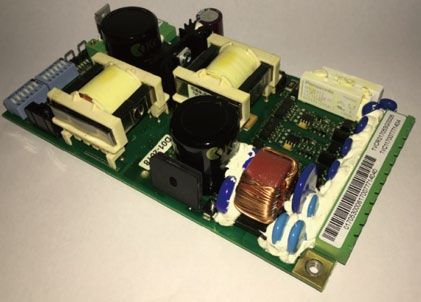
DESCRIPTION                                         7

Control module/feeder
As standard, the electronic control module is
fitted with a connector with screw terminal board
for connection of the auxiliary circuits.

Technical documentation
For more in-depth technical and application
aspects of the VSC contactors, also consult the
publication on UniGear ZS1 code 1YHA000015.

Quality system
Conforms to the ISO 9001 standards, certified by
an external independent organization.

Environmental management system
Conforms to the ISO 14001 standards, certified
by an external independent organization.

Health and safety management system
Conforms to the OHSAS 18001 standards,
certified by an external independent
organization.
V-Contact VSC Medium voltage vacuum contactors - ABB
8                           V-CONTACT VSC PRODUCT BROCHURE

—
Contactor selection and ordering

General characteristics                                                  IEC 62271-106   VSC 7, VSC/F 7, VSC/P 7
                                                                         GB/T 14808      Contactor                  Combined with
                                                                                         3.4.105                    fuses 3.4.110.5
Rated voltage                                      Ur [kV]               4.1             7.2                        7.2
Withstand voltage at 50 Hz                         Ud (1 min) [kV]       4.2             30                         30
Impulse withstand voltage                          Up [kVp]              4.2             60                         60
Rated frequency                                    fr [Hz]               4.3             50-60                      50-60
                                                                                                                    (1)
Rated current                                      le [A]                4.101           400
Short-time withstand current for 1 s               lk [A]                4.5             6,000                      6,000
Short-circuit withstand current for 30 s           lk [A]                4.5             2,400                      2,400
Rated peak current                                 lp [kA peak]          4.6             15                         15
Rated short-circuit time                           tk [s]                4.7             1                          1
Breaking capacity up to (with fuses)               lsc [kA]              4.107           -                          50 (2)
Short-circuit making capacity up to (with fuses)   lma [kA]              4.107           -                          50 (2)
Short-circuit breaking capacity                    [A]                   4.107, 6.104    5,000                      -
Short-circuit making capacity                      [peak A]              4.107, 6.104    13,000                     -
Limit above which the fuse blows(4)                [A]                   4.107.3         -                          5,000
Number of operations (rated values)
            Contactor SCO                          time/h                4.102           1200                       1200
            Contactor DCO                          time/h                4.102           1200                       1200
Maximum rated admissible overcurrent for           [kA]                  -               55                         -
1/2 period (peak value)
Rated load and overload characteristics in
category of use:
    (Category AC4) 100 closing operations          [A]                   4.103, 4.104    4,000                      4,000
    (Category AC4) 25 opening operations           [A]                   4.103, 4.104    4,000                      4,000
Rated voltage of the switching devices and                               4.8, 4.9
auxiliary circuits
Feeder type1 (24 ... 60 DC)                                              ■               ■                          ■
Feeder type 2 (110 ... 250 AC-DC)                                        ■               ■                          ■
                  7)
Mechanical life                                                          4.105           1,000,000                  1,000,000
Electrical life (category AC3)(3)                                        4.106           100,000                    100,000
Electrical life at rated current                                         4.106           1,000,000                  1,000,000
Apparatus wear classification (type)                                     4.107.3         C                          C
Switching times
Opening time                                       [ms]                  -               35-60                      35-60
Closing time                                       [ms]                  -               60-90                      60-90

                                                                                         VSC 7
Ultimate performances for Rated voltage            [kV]              -                   2.2/2.5            3.3                 3.6/5
• Motors                                           [kV]              -                   1,000              1,500               1,500
• Transformers                                     [kVA]             -                   1,100              1,600               2,000
• Capacitors                                       [kVAr]            -                   1,000              1,500               1,500
Ultimate performances for back-to-back                                                   VSC12 (6)
capacitor banks Rated voltage
• Rated voltage                                    [kV]              -                   2.2/2.5            3.3                 3.6/5
• Rated current                                    [A]               -                   250                250                 250
• Maximum transient current of the capacitor       [kA]              -                   8                  8                   8
• Maximum transient frequency of                   [kHz]             -                   2.5                2.5                 2.5
    capacitor connection
V-Contact VSC Medium voltage vacuum contactors - ABB
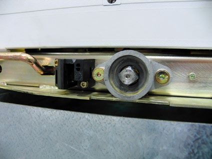
CONTACTOR SELECTION AND ORDERING                                                                                         9

VSC, VSC/F 12, VSC/P 12, VSC-S/GB, VSC-S/PGB
Starter 3.4.105                  Combined with
                                 fuses 3.4.110.5
12                               12
42                               42
75                               75
50-60                            50-60
                                 (1)
400
6,000                            6,000
2,400                            2400
15                               15
1                                1
-                                50 (2)
-                                50 (2)
5,000                            -
13,000                           -
-                                4,000

1200                             1200
1200                             1200
55                               -

4,000                            4,000
4,000                            4,000

■                                ■
■                                ■
                                                          (1) Depending on the capacity of the coordinated fuse.
1,000,000                        1,000,000                (2) Value linked to the breaking capacity of the fuse: refer to the fuse manufacturer
                                                              documentation.
100,000                          100,000                  (3) Electrical life obtainable by following the maintenance programme given in the
1,000,000                        1,000,000                    installation manual.
                                                          (4) This is the current value determined by intersection of the time-current trip curves
C                                -                            of two protection devices in this case the fuse and any thermal protection relay.
                                                          (5) Overvoltage dischargers or RC filters must be fitted.
                                                          (6) For these applications use VSC 12 up to 7.2 kV instead of VSC 7.
35-60                            35-60                    (7) VSC-S/GB、VSC-S/PGB mechanical life is 200000.
60-90                            60-90

                                 VSC 12-400 A
6.2/7.2                          12
3,000                            5,000
4,000                            5,000
3,000                            4,800 5)
                                 VSC-S/GB, VSC-S/PGB

6.2/7.2                          12
250                              150
8                                8
2.5                              2.5
V-Contact VSC Medium voltage vacuum contactors - ABB
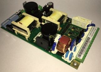
10                    V-CONTACT VSC PRODUCT BROCHURE

Weight and overall                                      Fixed                             Withdrawable
excluding the fuses               VSC 7       VSC/F 7     VSC 12     VSC/F 12   VSC/P 7         VSC/P 12
                                                          VSC-S/GB                              VSC-S/PGB
Weight                   [kg]     20          35          20         35         52              52
Overall                  H [mm]   421         494         441        532        635             635
                         W [mm]   350         466         350        466        53              531
                         D [mm]   228         622         228        702        657             657
CONTACTOR SELECTION AND ORDERING                                                                                                    11

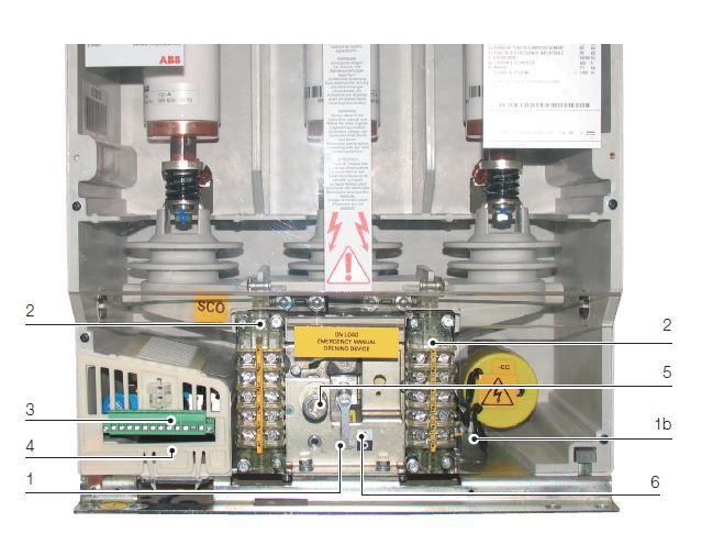
Standard fittings                                                      The electrical characteristics must conform to
                                                                       the IEC 60282-1 standards.

                                                                       The fuseholder is fitted with a special kinematics
                                                                       mechanism which automatically opens the
                                                                       contactor when even a single fuse blows and
                                                                       prevents contactor closing when even a single
                                                                       fuse is missing.

                                                                     8. Isolation interlock with the truck (only
                                                                        withdrawable contactor). This prevents isolation
                                                                        or racking-in the contactor into the switchgear
                                                                        if the apparatus is in the closed position, and
                                                                        also prevents contactor closing during the
                       VSC 7-VSC 12                                     isolation run.

                                                                     9. Operation counter
1. MAC Drive with permanent magnets with
                                                                       Mechanical operation counter for fixed
   capacitor for storing energy (1b)
                                                                        versions, electric operation counter for
                                                                        withdrawable versions. This is a device which
2. Auxiliary contacts
                                                                        counts the contactor closing cycles.
Contactor                 Choices     Normally open       Normally
                          available                       closed     Characteristics of the auxiliary contacts of the
VSC 7, VSC/F 12           1           5                   5          contactor
VSC 12, VSC/F 12,         1           5                   5
                                                                     Rated voltage             24...250 V AC/DC
VSC-S/GB
                                                                     Rated current Ith         10 A
VSC/P 7                   1           5 (SCO)-4 (DCO) 5
                                                                     Insulation voltage        2000 V-1 min 50 Hz
VSC/P 12, VSC-S/GB        1           5 (SCO)-4 (DCO) 5
                                                                     Electric resistance       ≤15 mΩ
                                                                     Un                    Cos          T           In        Icu
                                                                     220 V~                0.3          -           2.5 A     25 A
3. Multi-voltage feeder. Different power supply
                                                                     24 V-                 -            40 ms       10 A      12 A
ranges are available:
                                                                     60 V-                 -            40 ms       6A        8A
Feeder LV                        Feeder HV                           110 V-                -            40 ms       4A        5A
24 V d. c.        110 V d. c.               220 V d. c.              220 V-                -            40 ms       2.5 A     2.5 A
30 V d. c.        110 V a. c. 50-60 Hz      220 V a. c. 50-60 Hz
48 V d. c.        120 V d. c.               230 V d. c.
                                                                     "Control coil continuity" and "capactity survey"
60 V d. c.        120 V a. c. 50-60 Hz      230 V a. c. 50-60 Hz
                                                                     contacts characteristics
                  125 V d. c.               240 V d. c.
                  125 V a. c. 50-60 Hz      240 V a. c. 50-60 Hz     Technology                         Wipe contacts relay
                  127 V d. c.               250 V d. c.              Switchingcharacteristics:
                  127 V a. c. 50-60 Hz      250 V a. c. 50-60 Hz     Maximum switching power            1,200 VA (on resistive load)
                  130 V d. c.                                        Maximum switching voltage          277 V AC, 300 V DC
                  130 V a. c. 50-60 Hz                               Maximum switching current          3A
                                                                     Maximum rated current              5 A@4 s
4. Socket/plug with terminal at terminal box                         Contacts characteristics:
                                                                     Maximum on resistance(Ron)         150 mΩ (measurec by
5. Manual emergency opening operation                                                                   voltage drop 6 V DC 1 A)
                                                                     Maximum capactitance               1.5 pF
6. Mechanical open/closed indicator                                  Timing characteristics:
                                                                     Maximum actuating time             5.0 ms
7. Fuseholders (only for VSC/P and VSC/F)                            Maximum releasing time             2.0 ms
   The withdrawable contactor is fitted with
                                                                     Insulation:
   fuseholders able to hold DIN or BS type fuses
                                                                     Between contacts and coil          3,000V rms (50 Hz/1 min.)
   according to what the customer requests.
                                                                     Between open contacts              750 V rms (50 Hz/1 min.)
                                                                     Resistance (Roff)                  Min. 1000 MΩ at 500 V DC
  The fuses must have the dimensions and striker
  of average type according to DIN 43625 standards
  with maximum cartridge size e=442 mm and BS
  2692 with maximum cartridge size L=553 mm.
12   V-CONTACT VSC PRODUCT BROCHURE

     Optional accessories
     The table below indicates availability of the accessories in relation to the various types of contactor.

     Table of accessory availability           VSC 7   VSC/F 7         VSC/P 7         VSC 12           VSC/F 12       VSC/P 12
                                                                                       VSC-S/GB                        VSC-S/PGB
     1a Interfacing shaft on feeder side       ■       ■
     1b Interfacing shaft on capacitor side    ■       ■                               ■                ■
     2 Undervoltage function (only for DCO)    ■       ■               ■               ■                ■              ■
     3 Adapter for fuses                               ■               ■                                ■              ■
     4 Connection alternative to the fuses             ■               ■                                ■              ■
     5 Isolation lock                                                  ■                                               ■
     6 Locking magnet in the truck                                     ■                                               ■
     7 Lock for different rated currents (1)                           ■                                               ■
     8 Motorised truck                                                 ■                                               ■

     (1) Compulsory for UniGear switchgear.

                                                                 1 Interfacing shafts
                                                                 These can be used to interface the apparatus
                                                                 with the kinematics of the switchgear to make
                                                                 interlocks and/or signals.
                                        36
                                                                 The length of interfacing shafts is 36 mm, the
                                                                 mounting as indicated in the following table.

                                                                 Position                    Feeder             Capacitor (right,
                                                                                             side (left)        see picture)
                                                                 VSC 7, VSC/F 7              ■                  ■
                                                                 VSC 12, VSC/F 12,           -                  ■
                                                                 VSC-S/GB

                                                                 Note: for the utilization parameters (angles and forces applicable),
                                                                 please refer to the manual.

                                                                 2 Undervoltage function
                                                                 First of its type, the V-Contact VSC contactor is
                                                                 fitted with an undervoltage function with
                                                                 selectable delays of 0, 0.5, 1, 2, 3, 4, 5 s.

                                                                 This accessory must be specified at the time of
                                                                 order because it cannot be mounted at a later
                                                                 stage.
CONTACTOR SELECTION AND ORDERING                                                      13

                                   3 Adapter for application of fuses
                                   The kit includes all the accessories needed to
                                   adapt and mount three fuses (according to DIN
                                   Standards with dimension e less than 442 mm;
                                   according to BS Standards with dimension L less
                                   than 553 mm).

                                   The kit can be installed directly onto the fuseholder
                                   supports. The fuses must have dimensions and
                                   striker of average type according to DIN 43625
                                   and BS 2692 (1975) Standards. The electrical
                                   characteristics must conform to the IEC 282-1
                                   (1974) Standards.
                DIN      D

                e
                                   To select the fuses, see "Conditions of use
                                   according to the load"-chapter 3. The adaptation
                                   kits are available in the following types: 3A For
                    BS
                                   fuses according to DIN Standards with distance
                 4xØxL
                                   e=192 mm 3B For fuses according to DIN Standards
                                   with distance e=292 mm 3D For fuses according
                    BS
                                   to BS Standards (4x10xL=305 mm) 3E For fuses
                                   according to BS Standards (4x10xL=410 mm) 3F
                    L              For fuses according to BS Standards with distance
                                   L=454 mm.

                                   4 Connections alternative to the fuses
                                   The kit includes three flat copper busbars and
                                   fixing screws to be installed when the fuses are
                                   not needed.

                                   The kit can be installed directly onto the fuseholder
                                   supports.

                                   5 Isolation lock
                                   Isolation lock for UniGear type ZS1 switchgear and
                                   PowerCube modules.

                                   It prevents the apparatus from being racked-in if
                                   the unit door is open.

                                   This lock only works if the door of the switchgear/
                                   enclosure is also fitted with the corresponding
                                   lock.
14   V-CONTACT VSC PRODUCT BROCHURE

                                      6 Locking magnet in the truck
                                      This only allows the withdrawable contactor to be
                                      racked into/out of the enclosure with the
                                      electromagnet energised and the contactor open.

                                      The table below shows the power supply voltages
                                      available.

                                      Un                           Un          F
                                      24 V-                        120 V~      50 Hz
                                      30 V-                        127 V~      50 Hz
                                      48 V-                        220 V~      50 Hz
                                      60 V-                        230 V~      50 Hz
                                      110 V-                       240 V~      50 Hz
                                      125 V-                       Un          Un
                                      220 V-                       110 V~      60 Hz
                                      Un        F                  120 V~      60 Hz
                                      24 V~     50 Hz              127 V~      60 Hz
                                      48 V~     50 Hz              220 V~      60 Hz
                                      60 V~     50 Hz              230 V~      60 Hz
                                      110 V~    50 Hz              240 V~      60 Hz

                                      7 Lock for different rated currents (only
                                      withdrawable versions)
                                      This prevents insertion of the plug-socket and
                                      therefore apparatus closing, in a panel provided
                                      for a circuit-breaker.

                                      This lock, which is compulsory for UniGear
                                      switchgear, requires the same lock provided on
                                      the enclosure/switchgear.

                                      8 Motorised truck
                                      Only available for VSC/P for use in UniGear
                                      switchgear and PowerCube units. This
                                      application must be specified at thetime of
                                      ordering the contactor and cannot be mounted
                                      at alater stage.
SPECIFIC PRODUCT CHARACTERISTICS                                                                      15

—
Specific product characteristics

       Electromagnetic compatibility                       and their accessories comply with climate graph
       The V-Contact VSC vacuum contactors ensure          no. 8 of the IEC 7212-1 and IEC 68-2-2 (Test B: Dry
       operation without unwarranted trips when there      Heat)/IEC 68-2-30 (Test Bd: Damp Heat, cyclic)
       are interferences cause by electronic apparatus,    Standards.
       by atmospheric disturbances or by discharges of
       electrical type. Moreover they do not produce any   Installation of fixed contactors
       interference with electronic apparatus in the       The performance of the contactor remains
       vicinity of the apparatus.                          unaltered in the installation positions indicated:
                                                           A) Wall-mounted with moving contacts at the
       The above is in compliance with IEC 62271-1,           bottom.
       62271-106, 61000-6-2, 61000-6-4 Standards, as       B) Wall-mounted with moving contacts at the top.
       well as with the EEC 89/336 European Directive
       regarding electromagnetic compatibility (EMC),      Altitude
       and the feeders are CE marked to indicate their     It is well-known that the insulating properties of
       compliance.                                         air decrease as the altitude increases.

       Resistance to vibrations                            This phenomenon must always be taken into
       V-Contact VSC contactors are unaffected by          account during the design stage of insulating
       mechanically or electromagnetically generated       parts of equipment which is to be installed over
       vibrations.                                         1000 m about sea level. In this case a correction
                                                           coefficient must be applied, which can be taken
       Tropicalisation                                     from the graph drawn up according to the
       V-Contact vacuum contactors are manufactured        indications given in the IEC 62271-1 or GB/T 11022
       in compliance with the prescriptions regarding      standards.
       use in hot-humid-saline climates. All the most
       important metal parts are treated against           For altitudes above 1000 m, ask ABB.
       corrosive factors corresponding to ambient
       conditions C in compliance with the UNI 3564-65     Environmental protection programme
       Standards.                                          The V-Contact VSC contactors are constructed in
                                                           compliance with the ISO 14000 Standards
       Galvanization is carried out in compliance with     (Guidelines for environmental management).
       the UNI ISO 2081 Standard, classification code
       Fe/Zn 12, with thickness of 12x10-6 m, protected    The production processes are carried out in
       by a layer of conversion mainly consisting of       compliance with the Standards for environmental
       chromates in compliance with the UNI ISO 4520       protection both in terms of reduction of energy
       Standard. These construction characteristics        consumption and raw materials and of production
       mean that all the V-Contact VSC series apparatus    of waste. All this is thanks to the environmental

       VSC 7 - VSC 12 - VSC-S

           A                                                  B
16   V-CONTACT VSC PRODUCT BROCHURE

     management system in the production facility            Searching for trip coordination with the other
     conforming to what is certified by the certifying       protection releases in order to adequately protect
     Organisation.                                           the contactor, current transformers, cables, the
                                                             motor itself and all the other apparatus present
     The minimal environmental impact during the life        in the circuit, which could be damaged by
     cycle of the product (LCA-Life Cycle Assessment),       prolonged overloads or by a specific let-through
     is obtained by targeted selection of materials,         energy (I2t) higher than the one which can be
     processes and packing made during the design            withstood, also figures among the selection
     stage. The production techniques prepare the            criteria.
     products for easy dismantling and easy separation
     of the components to allow maximum recycling            Protection against short-circuit is carried out by
     at the end of the useful life cycle of the apparatus.   the fuses, always selected with a rated current
                                                             higher than that of the motor to prevent their
     For this purpose, all the plastic components are        intervention on start-up. This method of selection
     marked according to ISO 11469 (2nd ed. 15.05.2000).     does not, however, allow their use as protection
                                                             against repeated overloads-a function already
     When compared with a contactor fitted with a            not guaranteed by them, especially with current
     traditional operating mechanism, V-Contact VSC          values included up to the end of the initial
     contactors allow an energy saving which prevents        asymptotic stretch of the characteristic curve.
     emission into the atmosphere of about 7000 kg
     of carbon dioxide (CO2).                                A release with inverse or independent time is
                                                             therefore always needed for protection against
     Use of fuses according to the load                      overloads. This protection must be coordinated
     Motor control and protection                            with the one carried out by the fuse, working so
     The motors are supplied in low voltage, normally        that the release and fuse curves intersect at a
     up to a power of 630 kW. Over the latter power,         point to allow the following:
     medium voltage power supply is preferable (from         1) Motor protection against overcurrents due to
     3 to 12 kV) with the aim of reducing costs and             overloads, single-phase running, blocked rotor
     dimensions of all the apparatus which are part of          and repeated startups. Protection entrusted
     the circuit. The V-Contact can be used for voltages        to an indirect relay with inverse or definite
     from 2.2 kV up to 12 kV and for motors up to a             time delay trip which acts on the contactor.
     power of 5000 kW, thanks to the simplicity and          2) Protection of the circuit against fault currents,
     sturdiness of the control mechanisms and the               between phases and towards earth, of low
     long life of the main contacts.                            value, entrusted to a release with inverse or
                                                                definite time delay trip, which must only
     To ensure protection against short-circuit, it is          intervene for the short-circuit values which
     necessary to combine the contactors with                   can be interrupted by the contactor.
     appropriate currentlimiting fuses. This solution        3) Protection of the circuit against fault currents
     allows the costs of the loadside apparatus (cables,        higher than the breaking capacity of the
     current transformers, busbar and cable anchoring           contactor up to the maximum fault withstand
     devices, etc.) to be further reduced and to make           current. Protection entrusted to the fuse.
     the user practically independent of any subsequent
     enlargements of the plant and of the consequent         To verify the service conditions, the proceed as
     increased in network power.                             follows:
                                                             • Rated voltage Un
     Procedure for selecting the fuses for motor               This must be equal to or higher than the service
     protection (1)                                            voltage of the installation.
     Selection of the fuses suitable for motor protection
     must be made by verifying the service conditions.         Check that the level of insulation of the network
                                                               is higher than the switching overvoltage value
     The data to be taken into consideration are:              generated by the fuses, which for the fuses
     • Power supply voltage                                    used by ABB is widely below the limit fixed by
     • Start-up current                                        the IEC 282-1 Standards.
     • Duration of start-up
                                                             (1) The selection criterion indicated refers to ABB type CMF fuses.
     • Number of start-ups/hour
     • Current at full motor load
     • Short-circuit current of the installation
SPECIFIC PRODUCT CHARACTERISTICS                                                                                17

—
Fig. A Fuse selection   • Rated current In                                       • Short-circuit current
curves for motor          This must be selected by consulting the diagrams         The short-circuit current limiting curves in fig.
start-up.
ABB CMF type fuses.       indicated in fig. A which refer to the case of           C allow the short-circuit current limitation on
                          starting at fairly even time intervals, except for       the load side of the fuses involved in the fault to
                          the first two start-ups of each hourly cycle which       be appreciated. And this implies smaller sizing
                          can take place in immediate succession.                  of the load side apparatus.

                          Each diagram refers to a different starting time:      Example of coordination for overload of a
                          6 s-15 s-60 s, respectively.                           fuserelay with inverse time delay trip
                                                                                 Motor characteristics:
                          In the case of start-ups close together, it must       Pn                         =1000 kW
                          be checked that the starting current does not          Un                         =6 kV
                          exceed the value of IfxK, where If is the fuse         lstart                     ≈5 In=650 A
                          blowing current in correspondence with the             Tstart                     =6 s
                          starting time of the motor, and K is a minor           No. hourly operations      =16
                          factor of the unit, a function of the In of the
                          fuse and which can be taken from the table             In the curve with starting time of 6 s in fig. A, in
                          given in figure B.                                     correspondence with the 650 A starting current
                                                                                 value, the straight line, traced for 16 hourly
                        • Full load motor current                                start-ups, intersects in the range of the 250 A
                          The rated current of the fuse must be of a value       fuse.
                          equal to or higher than 1.33 times the rated
                          current value of full motor load.                      In the fuse blowing time curve, it can be noted
                                                                                 that the 250 A fuse blows in 6 s (starting time)
                          This condition is, in any case, always obtained        when it is passed through by a current of 1800 A.
                          for motors started at full voltage for which the
                          procedure described for selection of the rated
                          fuse current necessarily imposes values which
                          are always higher than 1.33 In.

                          In (A)                                                  In (A)

                                                                                                                                  IA (A)

                                                                        IA (A)

                          In (A)

                                                                                 In =rated current of the fuse
                                                                                 IA =motor start-up current
                                                                                 Nh =number of motor start-ups in one hour
                                                                                 tA =maximum motor start-up time

                                                                        IA (A)

                        —
                        Fig. A
18                       V-CONTACT VSC PRODUCT BROCHURE

—
Fig. B Curve of fuse     In the table in fig. B, the K coefficient for the 250     It must be remembered that prolonged overheating,
blowing times and        A size is 0.6, from which the value IfxK=1080 A is        above the temperature foreseen for the class of
table for selection of
factor K. ABB CMF        taken, which is higher than the start-up current          insulating materials, is harmful and strongly
type fuses.              (650 A), so use of the 250 A fuse is also legitimate      prejudices the life of electric machines.
—
Fig. C Short-circuit     in respect of this condition, which regards the
current limitation       possibility of start-ups close together.                  Fig. D shows the graph relative to the motor
curves. ABB CMF
type fuses.                                                                        considered in the example.
                         By observing the blowing curve of the 250 A fuse,
                         the need to use a relay with inverse time delay trip,
                         or a relay with definite time delay trip for protection
                         against overloads can be noted.

                          tf (S)                                                    Ip (kA)

                                                                         If (A)

                                                                                                                                         Is (kA)

                                                                                   Is =prospective short-circuit symmetrical current
                                                                                   Ip =current limited by the fuse (peak value)

                                                                                   —
                                                                                   Fig. C

                                                                                   Table for selection of factor K
                                                                                   Un (kV)       In (A)
                                                                                   3.6      63       100    160        200         250    315
                                                                                   7.2      63       100    160        200         250    315
                                                                                   12       63       100    160        200         -      -
                                                                                   K        0.75    0.75    0.7        0.7         0.6    0.6

                         —
                         Fig. B
SPECIFIC PRODUCT CHARACTERISTICS                                                                                             19

—
Fig. D Graph showing     Motor starting                                                              The full voltage start-up condition can be checked
the coordination         Motor starting poses the problem of the high                                analytically and turns out to be possible in most
between 250 A fuse
and relay with inverse   current consumption on inrush.                                              cases.
time delay trip.

                         In most cases, since these are asynchronous                                 If the calculations show that the start-up power
                         motors, the start-up current can take on the                                causes a voltage drop higher than the admissible
                         following values:                                                           one, starting with reduced voltage must be used,
                         • Asynchronous with simple squirrel cage 4.5 ...                            with consequent reduction in the start-up current.
                           5.5 In
                         • Asynchronous with double squirrel cage 5 ... 7 In                         For this purpose, starting with a step-down
                         • Asynchronous with wound motor: low values,                                autotransformer is generally used.
                           dependent on selection of the starting
                           resistances                                                               For large motors it may be more convenient to use
                                                                                                     a transformer, whose sizing can be a little higher
                         This current cannot be available if the short-circuit                       than the power required by the motor, dedicated
                         power of the network is not sufficiently high and,                          exclusively to the machine:
                         in any case, can give rise to a drop in voltage for                         Start-up therefore takes place with reduced
                         the whole duration of starting, which cannot be                             voltage (strong voltage drop on the secondary
                         tolerated, from the loads derived from the network                          winding of the transformer) without the rest of
                         itself. Normally a voltage drop between 15 and 20%                          the plant being affected.
                         is considered acceptable except for verification
                         needed in the case of special users.

                                   t

                                                                                                                        Wiring diagram
                                       In

                                                    T                                                                            F
                                                                       Icn

                                                                                                                                         K51
                                                        Ia

                                                                               F

                                                                          Ip                               I (A)

                         —
                         Fig. D

                         Icn=maximum short-circuit current in amperes that the contactor can interrupt
                         Ia=motor start-up current in amperes
                         In=motor rated current in amperes
                         t=time in seconds
                         I=current in amperes
                         F=time-current characteristic of the 250 A fuse
                         T=inverse time characteristics of the indirect relay for protection against overloads (K51)
                         Ip=peak value of the motor connection current
20                  V-CONTACT VSC PRODUCT BROCHURE

—
Fig. E Typical      By suitably combining different enclosures, with                   Transformer protection and fuse selection (1)
diagrams of         withdrawable contactors appropriately fitted                       When contactors are used for transformer control
transformer power
supply and motor    with accessories, any motor starting, control,                     and protection, they are fitted with special types
starting            protection and measurement diagram can be                          of current-limiting fuses which guarantee
                    made.                                                              selectivity with other protection devices and
                                                                                       which can take the high transformer connection
                    Fig. E shows some typical electric diagrams which                  currents without deterioration.
                    can be made with withdrawable contactors.
                                                                                       Unlike what has been seen for motors, in this case
                                                                                       protection against overcurrents on the medium.

                                                                                       (1) Selection criteria relative to ABB CEF type fuses.

                    1 Transformer power supply    2 Motor starting with full voltage        3 Reversal of motor running      4 Motor starting with dedicated
                                                                                                                               transformer

                    5 Star-delta motor starting                       6 Motor starting with reactor                   7 Motor starting with autotransformer

                    —
                    Fig. E
SPECIFIC PRODUCT CHARACTERISTICS                                                                                       21

voltage side of the transformer is not indispensable           Connection of capacitors
since this task is carried out by the protection               The presence of current transients, which occur
provided on the low voltage side. The protection               during switching-in of a capacitor bank, requires
on the medium voltage side can be entrusted to                 attention during the calculation procedures. In
the fuse alone, which must be selected taking into             fact, assessment of the size of the phenomenon
account the no-load connection current, which can              provides the elements for selecting the switching
reach values up to 10 times the rated current for              apparatus suitable for connecting/disconnecting
smaller transformers built with orientated crystal             the bank and for guaranteeing its protection in
core laminations.                                              the case of overload.

The maximum connection current is reached when                 To make this calculation, the power factor
circuitbreaker closing takes place in                          correction installations must be divided into two
correspondence with passage through zero of                    types:
the voltage.                                                   1) Installations with a single three-phase capacitor
                                                                  bank (single bank installations)
Another result to be guaranteed is protection                  2) Installations with several three-phase capacitor
against faults in the low voltage winding and in                  banks, which can be connected separately
the connection stretch from this to the circuit-                  (multiple bank installations).
breaker located on the secondary winding, avoiding
the use of fuses with rated current which is too               In the first type of installations there is only one
high, to be able to ensure tripping within a short             type of switching-in transient, called switching-in
time even under these fault conditions.                        transient of a single capacitor bank to the network.
                                                               An example of a typical current transient is shown
A rapid check of the short-circuit current at the              in fig. A.
secondary terminals of the transformer and on
the supply side of the circuit-breaker on the                  In the second type of installations there are two
secondary, if placed at a significant distance,                types of switching-in transients:
allows the trip time to be verified on the fuse                • On connection of the first capacitor bank there
blowing curve.                                                   is the switching-in transient of a capacitor bank
                                                                 to the network
The table of use given below takes both the                    • On connection of the other banks there is a
required conditions into account, i.e. rated                     switchingin transient of a capacitor bank to the
current sufficiently high to prevent unwarranted                 network with other banks already supplied in
blowing during the no-load connection phase                      parallel. In this case, the current transient is the
and, in any case, of a value which guarantees                    type shown in fig. B.
protection of the machine against faults on the
low voltage side.

Selection table for fuses for transformers

Rated     Rated transformer power [kVA]
voltage   100         125    160    200      250   315   400     500    630    800   1000   1250   1600   2000   2500
[kV]      Rated fuse current [A]
3.6       40          40     63     63       63    63    100     100    160    160   200    250    315    --     --
5         25          25     40     40       63    63    63      100    100    160   160    200    250    250    315
6.6       25          25     26     40       40    63    63      63     100    100   100    160    200    200    250
7.2       25          25     26     40       40    63    63      63     63     100   100    160    160    160    200
10        16          16     25     25       25    40    40      63     63     63    100    100    160    160    160
12        16          16     16     25       25    25    40      40     63     63    63     100    100    160    160
22                      V-CONTACT VSC PRODUCT BROCHURE

—                       Trend of the current and voltage during and after the switching-in        Trend of the current and voltage during the first 10 ms of the
Fig. A Example of a     transient.                                                                switching-in transient.
current transient
during connection of
a single capacitor
bank.
—
Fig. B Example of a
current transient
during connection of
a capacitor bank with
another one already
supplied with
voltage.

                        —
                        Fig. A

                        a=Transient switching-in current: first peak at 600 A peak and 920 Hz frequency.
                        b=Transient voltage at the 400 kVAR bank terminals.
                        c=Power supply phase voltage 10/÷3=5.8 kV.
                        d=Rated bank current at 50 Hz: 23.1 A.

                        Trend of the current and voltage during the first 2 ms of the             Trend of the two components of the total current (see graph above).
                        switching-in transient.

                        —
                        Fig. B

                        a=Transient switching-in current: 1800 A peak and 4280 Hz frequency.
                        b=Transient voltage at the 400 kVAR bank terminals
                        c=Power supply phase voltage: 10/÷3=5.8 kV.
                        d=Component at 4280 Hz frequency of the transient switching-in current.
                        e=Component at 1260 Hz frequency of the transient switching-in current.
SPECIFIC PRODUCT CHARACTERISTICS                                                                                23

Selection of contactors suitable for connection         Two or more banks (back-to-back)
of capacitor banks                                      In the case of several capacitor banks, it is
The CEI 33-7 and IEC 871-1/2 Standards specify          necessary to make the calculations regarding the
that the capacitor banks "... must be able to           installation, considering operation of a single bank
operate correctly under overload with an effective      with the other capacitor banks already connected.
line current value up to 1.3 In, not taking into        Under these conditions, it is necessary to check
account the transients".                                that:
                                                        • The maximum switching-in current does not
The switching, protection and connection devices          exceed the value given below (see table)
must therefore be designed to withstand                 • The switching-in current frequency does not
continuously a current 1.3 times the current there        exceed the value given below (see table)
would be at the rated sinusoidal voltage and at the
rated frequency. According to the effective value       Contactor Peak current   Maximum switching    Ip (kA)
of the capacity, which may also be 1.10 times the                                -in frequency        xf (Hz)
rated value, this current can have a maximum value      VSC 7 400   8 kAp        2,500 Hz             20,000
of 1.3x1.10=1.43 times the rated current.               VSC 12 400 Ask ABB       Ask ABB              Ask ABB

It is therefore advisable to select the rated normal    For switching-in current values under the values
current of the contactor for operating the capacitor    indicated, the switching-in frequency can be
bank at least equal to 1.43 times the rated current     increased so that the product-Ip (kA) xf (Hz) -is
of the bank.                                            as indicated in the table.

The V-Contact VSC contactors completely fulfil          For example, in the case of the VSC 7 400 A
the requirements of the Standards, particularly         contactor, the Ip (kA) xf (Hz) value must not exceed
those regarding connection and disconnection            8x2, 500=20,000.
operations of banks and the overvoltages which,
in any case, do not exceed three times the peak         To calculate the switching-in current and frequency,
value of the rated phase voltage of the installation.   refer to the ANSI C37.012 Standards or to the IEC
                                                        62271-100 Annex H Standards.
It is necessary to apply overvoltage surge arresters
for the VSC 12 contactors.                              Should higher values than those indicated be
                                                        obtained in the calculations, it is necessary to
Single bank                                             connect air reactors of suitable value in the circuit.
The parameters of the current transient, peak
values and own frequency, which are present in          The use of reactors is, however, recommended in
the case of connection of the bank to the network,      the case of frequent operations with high
are usually of notably smaller size than those in       switching-in frequencies.
the case of multiple banks.
24                           V-CONTACT VSC PRODUCT BROCHURE

—
Overall dimensions

VSC 7 fixed contactor

Note (1): The interfacing shaft is able to endure Max. 2 Nm torque; Rotation angle is approximate to 10°.
Note (2): The installation position is 332×195 mm.
OVERALL DIMENSIONS                                                                                                               25

VSC 12, VSC-S/GB fixed contactor

                                                                                                                                   350
                                                                             215                   13
                             190.5                                                                                           115          115
50

                                                                             203
                                          7.5                                                                           3           112         3
                                                6

                                                    130
                                                6
391

                                                                                                                                                        36

                                                                                                                                                       (1)
                                                    237

                                                                                                                                                             148
                                                                                                  70

                                                                                                                                                       37
                                                                             170                               103.5         32    79     32
                                                                             215                                       156

                                                                                                              350
                      15                                                                                                                       8-Ø11
                30

                                 Ø1
                                      2

                      30
                                                                                     195
                                                                               215

                                                                                                                                               4-Ø20
                30

                                     Ø1
                                          2

                                                                                           32                                        32

                                                                                                             332

 Note (1): The interfacing shaft is able to endure Max. 2 Nm torque; Rotation angle is approximate to 10°.
 Note (2): The installation position is 332×195 mm.
26   V-CONTACT VSC PRODUCT BROCHURE

     VSC/P 7, VSC/P 12, VSC-S/PGB withdrawable contactor

                                                      205
                                                    (643)
                           120    29                629
                                       20
                                       19

                           100   35
                                              246
     20

                                                       264

                                                                  158
                                            113
     103

                                                                        80

                       19
                                                                             4

                                                                                                 433                  4
                                                                                           600
           14        503                                                                   657
                     530

                                                         VSC/P 12                VSC/P 7
                                                         VSC-S/PGB

                                                       Note (1): Tulip insert depth 18±3 mm.
                                                       Note (2): Distance of truck between test and service position 200 mm.
OVERALL DIMENSIONS                                                                                             27

VSC/F 7 fixed contactor with fuse holder

                                         B

                                                                                             A

                                             Note (1): The interfacing shaft is able to endure Max. 2 Nm torque;
                                                       Rotation angle is approximate to 10°.
                                             Note (2): The installation position is 332×195 mm.

VSC/F 12 fixed contactor with fuse holder

                                     B

                                                                                                 A

                                             Note (1): The interfacing shaft is able to endure Max. 2 Nm torque;
                                                       Rotation angle is approximate to 10°.
                                             Note (2): The installation position is 332×195 mm.
28     V-CONTACT VSC PRODUCT BROCHURE

—
Electric circuit diagram

       As an example, the diagram given below shows the contactor circuits. In any case, to take product
       evolution into account, it is always useful to refer to the circuit diagram provided with each piece
       of apparatus.

       VSC fixed contactor-DCO version (double command operated)
                                                                                                                                                                                                        1

              ~
                              -PFG           -PFR                 -SC                 -S0

       -XB                                                                                                                                             DCO: DOUBLE COMMAND OPERATED

                                                                                                                        Warning:
                                                                                                                        The voltage at the feeder terminals of the electronic
                                                                                                                        card and the control circuit (terminals 1-3-5-7-9 and
                                                                                                                        2-4-6-8-10) must come from a single auxiliary circuit
                                                                                                                        supply and from the same circuit-breaker.

                          -XB10:1        -XB10:3             -XB10:5              -XB10:7           -XB10:9

                      1              3                   5                     7                9
       -QB

              -AR             D0 1            D0 2                                      DI 1                  DI 2

                      2              4                   6                     8                8
                                                                                                                        -XB20:2     -XB20:1      -XB20:4       -XB20:3   -XB20:5    -XB20:6

                          -XB10:2    -XB10:4             -XB10:6                  -XB10:8       -XB10:10
                                                                                                                               2                         4                      5
                                                                                                                         -MO                       -MC                    -CC
                                                                                                                               1                         3                      6

       -XB

              ~

       VSC fixed contactor-SCO version (single command operated)
                                                                                                                                                                                                        3

                          ~                                                                                                        SCO: SINGLE COMMAND OPERATED
                                                                            -KA       -SC
                                            -PFG              -PFR                                       Warning:
       -XB1                                                                                              The voltage at the feeder terminals of the electronic card and the
        -XB                                                                           -S0                control circuit (terminals 1-3-5-11 and 2-4-6-12) must come from a
                                                                                                         single auxiliary circuit supply and from the same circuit-breaker.

       -QT

                                         -XB10:1     -XB10:3               -XB10:5             -XB10:11
                                                                                                                                                                                     -TR2 ~
       -QC                           1               3                 5                       11

                                                                                                                                                                                              ~
                      -AR                   D0 1               D0 2                                    DI 3

                                     2               4                 6                       12                                                                                                 -KA
                                                                                                         -XB20:2 -XB20:1       -XB20:4       -XB20:3   -XB20:5 -XB20:6
                                     -XB10:2         -XB10:4            -XB10:6                -XB10:12
                                                                                                                    2                    4                     5
                                                                                                              -MO                  -MC                   -CC
                                                                                                                    1                    3                     6

        -XB
       -XB1
ELECTRIC CIRCUIT DIAGRAM                                                                                                                                                                    29

VSC-S/GB fixed contactor-DCO version (double command operated)
                                                                                                                                                                                       11

         ~
                                                                                                                                 DCO: DOUBLE COMMAND OPERATED

                                                                                                       Warning:
                                                                                                       The voltage at the feeder terminals of the electronic
                                                                                                       card and the control circuit (terminals 1-3-5-7-9 and
-XB1                        -PFG           -PFR           -SC                   -SO                    2-4-6-8-10) must come from a single auxiliary circuit
                                                                                                       supply and from the same circuit-breaker.

                                                                                                                                                             7

                                                                                                                                                         1
                                                                                                                                                  -PC
                                                                                                                                                         2

                      -XB10:1        -XB10:3          -XB10:5             -XB10:7           -XB10:9                                            -XB40:1   -XB40:2

                      1              3                5               7                     9                                              1             2

-QC     -AR                 D0 1            D0 2             DI 1                   DI 2

                      2              4                6               8                     10
                       -XB10:2        -XB10:4         -XB10:6             -XB10:8           -XB10:10           -XB20:2      -XB20:1            -XB20:4   -XB20:3   -XB20:5   -XB20:6

                                                                                                           2                               4                       5
                                                                                                     -MO                         -MC                         -CC
                                                                                                           1                               3                       6
-XB1

             ~

VSC-S/GB fixed contactor-SCO version (single command operated)
                                                                                                                                                                                       13

                                                                                                                             SCO: SINGLE COMMAND OPERATED

                                                                                                      Warning:
                     -PFG          -PFR            -SC              -KA                               The voltage at the feeder terminals of the electronic
-XB1                                                                                                  card and the control circuit (terminals 1-3-5-11 and
                                                                                                      2-4-6-12) must come from a single auxiliary circuit
                                                   -SO
                                                                                                      supply and from the same circuit-breaker.

                                                                                                                                       7

                                                                                                                                   1
                                                                                                                           -PC
                                                                                                                                   2

                 -XB10:1       -XB10:3      -XB10:5          -XB10:11                                                    -XB40:1 -XB40:2

                 1             3            5                11                                                      1            2

-XB1   -AR            D0 1          D0 2              DI 3                                                                                                             -TR2 ~

                 2             4            6                12                                                                                                              ~
                 -XB10:2       -XB10:4      -XB10:6          -XB10:12                            -XB20:2 -XB20:1 -XB20:4 -XB20:3 -XB20:5 -XB20:6
                                                                                                                                                                                 -KA

                                                                                                 2                   4                           5
                                                                                      -MO                      -MC                     -CC
                                                                                                 1                   3                           6

-XB1
30   V-CONTACT VSC PRODUCT BROCHURE

     VSC/F fixed contactor-DCO version (double command operated)
                                                                                                                                                                                                                        1

                                                 ~
                                                                  -PFG           -PFR             -SC                  -SO
                            -PFG
                                                                                                                       3                                                     DCO: DOUBLE COMMAND OPERATED
     -XB
                                                                                                               -BF1
                                                                                                                       4
                                                                                                                                               Warning:
                                                                                                                                               The voltage at the feeder terminals of the electronic
                                                                                                                                               card and the control circuit (terminals 1-3-5-7-9 and
                        3              1
                                                                                                               1                 11            2-4-6-8-10) must come from a single auxiliary circuit
                                                                                                        -BF1            -BB2                   supply and from the same circuit-breaker.
             -BF2           -BF2                                                                               2                 12
                        4              2
     -QB

                                                                -XB10:1   -XB10:3             -XB10:5              -XB10:7          -XB10:9

                                                            1             3               5                    7                    9
                                           -AR

                                                 -AR               D0 1          D0 2                                   DI 1                DI 2

                                                            2             4               6                    8                    10
                                                                                                                                                   -XB20:2        -XB20:1 -XB20:4       -XB20:3   -XB20:5 -XB20:6
                                                                -XB10:2   -XB10:4         -XB10:6              -XB10:8           -XB10:10
                                                                                                                                                             2                     4                     5
                                                                                                                                                    -MO                     -MC                    -CC
     -XB                                                                                                                                                     1                     3                     6

                                                 ~

     VSC/F fixed contactor-SCO version (single command operated)

                                                                                                                                                                                                                        3

                                           ~                                                                                                        SCO: SINGLE COMMAND OPERATED
                                                                                        -KA       -SC
                                                           -PFG           -PFR                                               Warning:
     -XB1                                                                                                                    The voltage at the feeder terminals of the electronic card and the
     -XB                                                                                          -SO                        control circuit (terminals 1-3-5-11 and 2-4-6-12) must come from a
                                                                                                                             single auxiliary circuit supply and from the same circuit-breaker.

     -QT                                                                                                       1
                                                                                                        -BF1
                                                                                                               2
                    3              1
            -BF2        -BF2
                    4              2                   -XB10:1       -XB10:3        -XB10:5                         -XB10:11
                                                                                                                                                                                                             -TR2 ~
     -QC                                               1            3              5                           11

                                                                                                                                                                                                                 ~
                                       -AR                 D0 1           D0 2                                          DI 3

                                                       2            4              6                           12                                                                                                 -KA
                                                                                                                           -XB20:2       -XB20:1 -XB20:4         -XB20:3 -XB20:5       -XB20:6

                                                       -XB10:2       -XB10:4        -XB10:6                         -XB10:12
                                                                                                                                    2                    4                        5
                                                                                                                              -MO                  -MC                     -CC
                                                                                                                                    1                    3                        6

     -XB
     -XB1
ELECTRIC CIRCUIT DIAGRAM                                                                                          31

VSC, VSC/F, VSC-S/GB fixed contactor

                                                                                                              5

                         ~

                             -SO4

                  -XB1

                                                         13          23          33          43          53
                                                  -BB1        -BB1        -BB1        -BB1        -BB1
                                                         14          24          34          44          54

                               D0 1
                  -QC                  -XB10:11

                                       11

                                DI 3                     51          41          31          21          11
                         -AR
                                                  -BB2        -BB2        -BB2        -BB2        -BB2
                                                         52          42          32          22          12
                                       12
                                       -XB10:12

                  -XB1
32   V-CONTACT VSC PRODUCT BROCHURE

     VSC/P、VSC-S/PGB withdrawable contactor-DCO version (double command operated)
                                                                                                                                                                                                                                                       2
                                                                                                                                                                                                                            ~
                                        ~
                                                                                                                                                              DCO: DOUBLE COMMAND OPERATED
                                                    -PFG           -PFR                -SC                     -SO                                                                                                              -SO4
                                                                                                                                                          Warning:
                                                                                                                                                          The voltage at the feeder terminals                                               37
     -XB1           12

                                                                                                                                                                                                                                       37
                                                    25             43            26                  4         41               31                     13 of the electronic card and the control
                                                              43

                                                                          26
                                               25
               12

                                                                                                          41

                                                                                                                          31

                                                                                                                                                  13
      -XB

                                                                                               4
                                                                                                                                                          circuit (terminals 1-3-5-7-9 and
                                                                                        -XB7:11                3                                          2-4-6-8-10) must come from a single
                                                                                                     -BF1                                                 auxiliary circuit supply and from the
                                                                                      711A

      -QT
                                                                                               711

                                                                                                               4                                          same circuit-breaker.
                                                                                 -BT2        -BT1                   41A
                                                                                      712A

                        12A
                                                                                               712

                                                                                                                                11                                                        7
                                                                                        -XB7:12                     -BB2
                                                                                               4B

                                                                                                                                                                                      1
                                                                                                                          13A
                                                                                                     1                          12
                    3             1                                                          -BF1                                                                             -PC
                                                                                                                                                                                      2
            -BF2        -BF2                                                                         2
                                                                                               4A

                    4             2
                                                    -XB10:1 -XB10:3 -XB10:5                          -XB10:7                    -XB10:9                              -XB40:1          -XB40:2                                               -XB10:11
                                                    1              3             5                   7                          9                                    1               2                                                      11

     -QC                               -AR              D0 1           D0 2                  DI 1                    DI 2                                                                                                   -AR    DI 3

                                                    2              4             6                   8                          10                                                                                                          12
                                                    -XB10:2 -XB10:4 -XB10:6                          -XB10:8                    -XB10:10           -XB20:2 -XB20:1 -XB20:4 -XB20:3 -XB20:5 -XB20:6                                          -XB10:12

                                                                                                                                                   2                 4                              5
                                                                                                                                            -MO                -MC                        -CC
                                                                                                                                                   1                 3                              6
                                                              44

      -XB
               48

                                                                                                                          30
                                               35
                             47

                                                                                               14
                                                                          27

                                                                                                                                                                                                                                            38
     -XB1           48            47                35             44            27                  14                         30
                                                                                                                                                                                                                                             38

                                                                                                                                                                                                                            ~

     VSC/P、VSC-S/PGB withdrawable contactor-SCO version (single command operated)
                                                                                                                                                                                                                                                       3
                                                                                                                                                                              SCO: SINGLE COMMAND OPERATED
                                           ~                                                                                                      Warning:
                                                               -FPG                   -FPR           -KA           -SC
                                                                                                                                                  The voltage at the feeder terminals of the electronic card and the
                    12                                    25                  43                26                                                control circuit (terminals 1-3-5-11 and 2-4-6-12) must come from a
     -XB1           12                                    25                  43                26
      -XB                                                                                                          -SO                            single auxiliary circuit supply and from the same circuit-breaker.
               12

                                                                                                                                        31         36
                         12A
                                                                                                                     -XB2               1
     -QT
                                                                                                                     -BT3
                                                                                                                                                                                                7
                    3              1                                                                                 -XB2               2
            -BF2         -BF2                                                                                                                                                              1
                                                                                                                           4B

                                                                                                                                    1                                               -PC                                            -TR2      ~
                    4              2                                                                                     -BF1                                                              2
                                                                        43
                                                     25

     -QC                                                                                                                            2
                                                                                                                           4A

                                                                                                                                                                                                                                             ~
                                                          -XB10:1            -XB10:3            -XB10:5                              -XB10:11                                 -XB40:1      -XB40:2

                                                          1                  3                 5                                    11                                    1               2
                                                                                                                                                                                                                                             -KA
                                       -AR                                    D0 1              D0 2                                          DI 3

                                                          2                  4                 6                                    12
                                                           -XB10:2           -XB10:4            -XB10:6                             -XB10:12 -XB20:2         -XB20:1 -XB20:4          -XB20:3       -XB20:5       -XB20:6
                                                                                                                           30
                                                                        44
               48

                                                    35
                              47

                                                                                                                                                         2                      4                             5
      -XB               48            47                  35                  44                27                                   30            -MO                   -MC                            -CC
                        48            47                  35                  44                27                                   30                  1                      3                             6
     -XB1
ELECTRIC CIRCUIT DIAGRAM                                                                                                                                                                                                       33

VSC/P, VSC-S/PGB withdrawable contactor
                                                                                                                                                                                                                               5

                                                           1
         -SO4
                                                   -BD1
                          37                               2
                    37

-XB1                                                       45                      11                           5                               6                                    7          7            8            9
-XB                                                        45                      11                           5                               6                                    7          7            8            9
                                                     45

                                                                             11

                                                                                                                                                                                                        8
                                                                                                                                           6

                                                                                                                                                                                                                    9
                                                                                                           5

                                                                                                                                                                                7

                                                                                                                                                                                           7
                                                   -XB15 1
                                                           1
                                              -RL2
                                                           2

                                                                                        11A                          5A                                  6A                          7A
                                                                                                          206

                                                                                                                                          209
                                                                             202

                                                           2

                                                                                                                                                                                                                    218
                                              -XB15

                                                                                                                                                                                                       215
                          -XB10:11
                                                                                   21              13           31                 23           41                 33           11              43           51           53
                          11
                                                                        -BB2              -BB1          -BB2          -BB1              -BB2              -BB1           -BB2            -BB1        -BB2         -BB1
                                                                                   22              14           32                 24           42                 34           12              44           52           54
       -AR     DI 3
-QT
                          12
                          -XB10:12
                                                     46

                                                                                                                                                                                          39
                                                                                                                                                              28

                                                                                                                                                                                                                    29
                                                                                                                              33
                                                                                              22

                                                                                                                                                                                                       18
                                                                                                          15

                                                                                                                                          16
                                                                             21

                                                                                                                                                                           17
 -XB                                                       46                      21              22           15                 33           16                 28           17              39           18           29
-XB1                                                       46                      21              22           15                 33           16                 28                           39           18           29
                         38

                          38
                                                                                                                                                                        仅适用于SCO

                                                                                                                                          8

-XB1               49                         52                        55                57
-XB                49                         52                        55                57
                                                                                                                               32
             49

                                                                  55
                                        52

                                                                                    57

         -XB7                         -XB7                      -XB7           -XB7
                   1                          4                         7                 9
                                                                                                                          1    -XB11
                                        704

                                                                                    709
                                                                  707
             701

                   13           13            23           23           53                53
       -BT2             -BT1         -BT2          -BT1         -BT1          -BT2
                   14           14            24           24           54                54
                                                                  708
                                                     706
                                        705
             702

                          703

                                                                                    710

                                                                                                                     -MT
-QT                2            3             5            6            8                 10
         -XB7           -XB7          -XB7         -XB7         -XB7           -XB7

                                                                                                                          2
             50

                                                     54

                                                                                    58
                                                                 56
                                        53
                         51

                                                                                                                               42
-XB                50           51            53           54           56                58
-XB1               50           51            53           54           56                58

                                                                                                                                                     1        40
                                                                                                                                                     1        40
34   V-CONTACT VSC PRODUCT BROCHURE

     Control module

                                                       Digtal imput
                                                       D11     closed command (DCO)
                                                       D12     open command (DCO)
                                                       D13     undervoltage (DCO); DROP ORT(SCO)

                                                       Digtal output
                                                       D01 Unit ready
                                                       • Electronic device in working conditions
                                                       • Capactor working vltage
                                                       • Coil continuty

                                                       D02 System status information
                                                       • control bank capacitor status
                                                       • Temperature status (full options version only)

     State of operation represented                    BF1, BF2 =Position contacts of medium voltage
     The diagram indicates the following conditions:             fuses
     • Contactor open                                  RL2      =Locking magnet, if de-energized, it
     • Control circuits de-energized                             prevents contactor to be racked in/out
     • The fuse is installed without fusing state                of the enclosure
                                                       KA       =Auxiliary relay or contactor
     Caption                                           RD       =Diode
     XB      =Customer delivery terminal box of        PC       =Electric operation counter
              contact circuits                         TR2      =Rectifier
     XB1     =Switchgear terminal box (outside the
              contactor)                               Description of figures
     QC      =Contactor                                Fig.1-Fig.11 =Control circuits of the contactor
     QB      =Customer circuit-breaker or                            DCO version
              changeover device                        Fig.2        =Undervoltage only on request for
     MO      =Shunt opening release                                  DCO version
     MC      =Shunt closing release                    Fig.3-Fig.13 =Control circuits of contactor SCO
     SC      =Closing push-button                                    version
     SO      =Opening push-button                      Fig.4        =Locking magnet on the truck
     CC      =Capacitor                                Fig.5        =Auxiliary contacts of contactor
     AR      =Control and protection unit              Fig.6        =Contacts for electrically signaling
     BB1-BB2 =Auxiliary contacts (N_2 packs of 5                     contactor in the connected and
              contacts)                                              isolated positions, located on the
     BT1     =Contacts for electrically signaling                    truck
              contactor in the connected position      Fig.7        =Electric operation counter circuit
     BT2     =Contacts for electrically signaling      Fig.8        =motorized truck
              contactor in the isolated position
     BT3     =Contactor position contact-open          Note:
              during truck isolating travel            (1) The electric circuit diagram will be updated
     PRDY    =Signalling for control module ready          according to the development of product.
     SO4     =Pushbutton or contact for opening        (2) Fig.4 and Fig.8 can not be selected at the
              undervoltage contactor (contact              same time.
              closed with voltage present)
ELECTRIC CIRCUIT DIAGRAM                                                                    35

Graphic symbols for electric diagrams

                                                        Conductor in shielded cable (e.g.
             Thermal effect                             three conductors)

             Electromagnetic effect                     Connections of conductors

             Pushbutton control                         Terminal or clamp

             Earth (general symbol)                     Socket

             Conductive electric part,                  Socket and plug (female and male)
             frame

            Capacitor (general symbol)                  Power circuit-breaker with
                                                        automatic opening

            Potentiometer with moving contact           Control coil (general symbol)

            Make contact                                Electronic impulse counter

            Break contact
                                                        Lamp (general symbol)

            Changeover contact with
                                                DI...   Digital isolated binary inputs
            momentary interruption
36    V-CONTACT VSC PRODUCT BROCHURE

—
Product quality and environmental
protection

      The V-Contact VSC medium voltage vacuum                    The duty of company is to facilitate subsequent
      contactors are produced in compliance with the             recycling or disposal at the end of product life.
      requirements of international standards for the            During disposal of the product, it is always
      quality management system and environmental                necessary to act in accordance with local legar
      management system. In these fields, the excellent          requirements in force.
      level is proved by quality certificates according to
      ISO 9001 and by the EMS according to ISO 14001.            We use the following methods of disposal:
                                                                 Disposal can either be carried out thermally in an
      End of life of product                                     incineration plant or by storing on a waste site.
      The ABB Company is committed to complying
      with the relevant legal and other requirements
      for environment protection according to the ISO
      14001 standard.

      Raw wmaterial                                          Recommended method of disosal
      Metal material (Fe, Cu, Al, Ag, Zn, W, others)         Separation and recycling
      Thermoplasts                                           Recycling or disposal
      Epoxy resin                                            Separation of metal material and the disposal of rest
      Rubber                                                 Disposal
      Oil as dielectric (transformer oil)                    Draining from equipment and further recycling or disposal
      SF6 gas                                                Discharging from equipment and further recycling or disposal
      Packing material-wood                                  Recycling or disposal
      Packing material-foil                                  Recycling or disposal
—
Note

• • • • • • • • • • • • • • • • • • • • • • • • • • • • • • • • • • • • • • • • • • • • • • • • • • • • • • • • • • • • • • • • • • • • • •

• • • • • • • • • • • • • • • • • • • • • • • • • • • • • • • • • • • • • • • • • • • • • • • • • • • • • • • • • • • • • • • • • • • • • •

• • • • • • • • • • • • • • • • • • • • • • • • • • • • • • • • • • • • • • • • • • • • • • • • • • • • • • • • • • • • • • • • • • • • • •

• • • • • • • • • • • • • • • • • • • • • • • • • • • • • • • • • • • • • • • • • • • • • • • • • • • • • • • • • • • • • • • • • • • • • •

• • • • • • • • • • • • • • • • • • • • • • • • • • • • • • • • • • • • • • • • • • • • • • • • • • • • • • • • • • • • • • • • • • • • • •

• • • • • • • • • • • • • • • • • • • • • • • • • • • • • • • • • • • • • • • • • • • • • • • • • • • • • • • • • • • • • • • • • • • • • •

• • • • • • • • • • • • • • • • • • • • • • • • • • • • • • • • • • • • • • • • • • • • • • • • • • • • • • • • • • • • • • • • • • • • • •

• • • • • • • • • • • • • • • • • • • • • • • • • • • • • • • • • • • • • • • • • • • • • • • • • • • • • • • • • • • • • • • • • • • • • •

• • • • • • • • • • • • • • • • • • • • • • • • • • • • • • • • • • • • • • • • • • • • • • • • • • • • • • • • • • • • • • • • • • • • • •

• • • • • • • • • • • • • • • • • • • • • • • • • • • • • • • • • • • • • • • • • • • • • • • • • • • • • • • • • • • • • • • • • • • • • •

• • • • • • • • • • • • • • • • • • • • • • • • • • • • • • • • • • • • • • • • • • • • • • • • • • • • • • • • • • • • • • • • • • • • • •

• • • • • • • • • • • • • • • • • • • • • • • • • • • • • • • • • • • • • • • • • • • • • • • • • • • • • • • • • • • • • • • • • • • • • •

• • • • • • • • • • • • • • • • • • • • • • • • • • • • • • • • • • • • • • • • • • • • • • • • • • • • • • • • • • • • • • • • • • • • • •

• • • • • • • • • • • • • • • • • • • • • • • • • • • • • • • • • • • • • • • • • • • • • • • • • • • • • • • • • • • • • • • • • • • • • •

• • • • • • • • • • • • • • • • • • • • • • • • • • • • • • • • • • • • • • • • • • • • • • • • • • • • • • • • • • • • • • • • • • • • • •

• • • • • • • • • • • • • • • • • • • • • • • • • • • • • • • • • • • • • • • • • • • • • • • • • • • • • • • • • • • • • • • • • • • • • •

• • • • • • • • • • • • • • • • • • • • • • • • • • • • • • • • • • • • • • • • • • • • • • • • • • • • • • • • • • • • • • • • • • • • • •

• • • • • • • • • • • • • • • • • • • • • • • • • • • • • • • • • • • • • • • • • • • • • • • • • • • • • • • • • • • • • • • • • • • • • •

• • • • • • • • • • • • • • • • • • • • • • • • • • • • • • • • • • • • • • • • • • • • • • • • • • • • • • • • • • • • • • • • • • • • • •

• • • • • • • • • • • • • • • • • • • • • • • • • • • • • • • • • • • • • • • • • • • • • • • • • • • • • • • • • • • • • • • • • • • • • •
You can also read