Verdin iMX8M Plus Datasheet - Mouser Electronics Ecuador
←
→
Page content transcription
If your browser does not render page correctly, please read the page content below
Verdin iMX8M Plus Datasheet
Verdin iMX8M Plus Datasheet
Revision History
Date Doc. Rev. Module Version Changes
19-Oct-2020 Rev. 0.90 V1.0 Initial Release
Correction of CTRL_SLEEP_MOCI# signal type from open drain to
CMOS
23-Oct-2020 Rev. 0.91 V1.0
Section 1.6.4: Update document links for Wi-Fi module
Minor changes
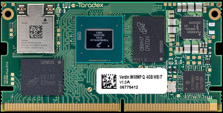
Add module picture on the front page
5-Jan-2021 Rev. 0.92 V1.0
Section 8.5: Clarify tolerances in drawing
Preliminary markings removed
Section 1.4: Verdin iMX8M Plus QuadLite 1GB IT added
Section 5.4: Correction of Figure 10
Section 5.5: Add Table 5-13 for clarification
Section 5.18: Correct to M7 core
22-Apr-2021 Rev. 0.93 V1.0 Section 8.3: Clarify maximum power consumption
Section 7: Link to errata page updated
Section 8.3: Rename the section to “Power Consumption”, update
section content
Section 8.6: Verdin iMX8M Plus QuadLite 1GB IT added
Minor changes
Toradex AG l Ebenaustrasse 10 l 6048 Horw l Switzerland l +41 41 500 48 00 l www.toradex.com l info@toradex.com Page | 2Verdin iMX8M Plus Datasheet
Contents
1. Introduction................................................................................................................... 5
1.1 Verdin SoM Family ............................................................................................................... 5
1.2 NXP i.MX 8M Plus SoC ........................................................................................................ 5
1.3 Verdin iMX8M Plus SoM ....................................................................................................... 6
1.4 Main Features ..................................................................................................................... 6
1.4.1 CPU ......................................................................................................................... 6
1.4.2 Memory .................................................................................................................... 7
1.4.3 Interfaces.................................................................................................................. 7
1.4.4 Graphics Processing Unit ........................................................................................... 8
1.4.5 HD Video Decode (VPU)............................................................................................ 8
1.4.6 HD Video Encode (VPU) ............................................................................................ 9
1.4.7 Image Signal Processor ............................................................................................. 9
1.4.8 Supported Operating Systems .................................................................................... 9
1.5 Interface Overview ............................................................................................................... 9
1.6 Reference Documents ........................................................................................................ 10
1.6.1 NXP i.MX 8M Plus ................................................................................................... 10
1.6.2 Ethernet Transceiver ............................................................................................... 11
1.6.3 ADC ....................................................................................................................... 11
1.6.4 Wi-Fi and Bluetooth Module ..................................................................................... 11
1.6.5 TPM 2.0 Module ...................................................................................................... 11
1.6.6 EEPROM ................................................................................................................ 11
1.6.7 RTC ....................................................................................................................... 11
1.6.8 Verdin Carrier Board Design Guide........................................................................... 11
1.6.9 Verdin Family Specification ...................................................................................... 11
1.6.10 Layout Design Guide ............................................................................................... 11
1.6.11 Toradex Developer Center ....................................................................................... 12
1.6.12 Verdin Carrier Board Schematics ............................................................................. 12
1.6.13 Toradex Pinout Designer ......................................................................................... 12
1.7 Naming Conventions .......................................................................................................... 12
1.7.1 Naming of NXP System on Chip ............................................................................... 12
1.7.2 Naming of Toradex Verdin Modules .......................................................................... 13
1.8 Build to Order Options ........................................................................................................ 13
2. Architecture Overview ................................................................................................. 14
2.1 Block Diagram ................................................................................................................... 14
3. Verdin iMX8M Plus Connector ...................................................................................... 15
3.1 Pin Numbering ................................................................................................................... 15
3.1 Assignment ....................................................................................................................... 16
4. I/O Pins ....................................................................................................................... 23
4.1 Function Multiplexing ......................................................................................................... 23
4.2 Pin Control ........................................................................................................................ 23
4.3 Pin Reset Status ................................................................................................................ 24
4.4 SoC Functions List ............................................................................................................. 25
5. Interface Description ................................................................................................... 29
5.1 Power Signals ................................................................................................................... 29
5.1.1 Power Supply Use Case Examples........................................................................... 31
5.2 GPIOs ............................................................................................................................... 35
5.2.1 Wakeup Source ...................................................................................................... 35
5.3 Ethernet ............................................................................................................................ 35
5.4 Wi-Fi and Bluetooth ........................................................................................................... 38
5.5 USB .................................................................................................................................. 40
5.6 Display .............................................................................................................................. 41
5.6.1 Display Serial Interface (DSI) ................................................................................... 42
Toradex AG l Ebenaustrasse 10 l 6048 Horw l Switzerland l +41 41 500 48 00 l www.toradex.com l info@toradex.com Page | 3Verdin iMX8M Plus Datasheet
5.6.2 HDMI ...................................................................................................................... 42
5.6.3 LVDS ..................................................................................................................... 43
5.7 Camera Interface ............................................................................................................... 45
5.8 PCI Express ...................................................................................................................... 47
5.9 I2C .................................................................................................................................... 48
5.9.1 Real-Time Clock (RTC)............................................................................................ 49
5.10 UART ................................................................................................................................ 49
5.11 SPI ................................................................................................................................... 51
5.12 Quad Serial Peripheral Interface (QuadSPI, QSPI) ............................................................... 52
5.13 PWM (Pulse Width Modulation) .......................................................................................... 53
5.14 SD/MMC ........................................................................................................................... 54
5.15 Digital Audio Interfaces ...................................................................................................... 55
5.15.1 Synchronous Audio Interface used as I2S.................................................................. 60
5.15.2 Synchronous Audio Interface used as AC’97 ............................................................. 61
5.15.3 PDM Microphone Interface ....................................................................................... 61
5.15.4 S/PDIF (Sony-Philips Digital Interface) ...................................................................... 62
5.16 Analog Inputs .................................................................................................................... 63
5.17 Controller Area Network (CAN) ........................................................................................... 64
5.18 JTAG ................................................................................................................................ 65
6. Recovery Mode............................................................................................................ 66
7. Known Issues .............................................................................................................. 67
8. Technical Specifications .............................................................................................. 68
8.1 Absolute Maximum Ratings ................................................................................................ 68
8.2 Recommended Operation Conditions .................................................................................. 68
8.3 Power Consumption ........................................................................................................... 68
8.4 Power Ramp-Up Time Requirements .................................................................................. 68
8.5 Mechanical Characteristics ................................................................................................. 69
8.5.1 Sockets for the Verdin Modules ................................................................................ 69
8.6 Thermal Specification ......................................................................................................... 70
8.7 Product Compliance ........................................................................................................... 71
Toradex AG l Ebenaustrasse 10 l 6048 Horw l Switzerland l +41 41 500 48 00 l www.toradex.com l info@toradex.com Page | 4Verdin iMX8M Plus Datasheet
1. Introduction
1.1 Verdin SoM Family
The Verdin System on Module (SoM) family eliminates much of the complexity associated with
modern-day electronic design. Complicated circuitry such as high-speed impedance-controlled
layouts with high component density utilizing blind and buried via technology is encapsulated on
the SoM. This allows the customer to create a carrier board that focuses solely on application-
specific electronics, making the project substantially less complex. The Verdin module takes this
one step further and implements an interface pinout that allows direct connection of real-world I/O
ports without the need to cross traces or traverse layers, referred to as Direct Breakout™. This
becomes increasingly important for customers as more interfaces move toward high-speed serial
technologies that require impedance-controlled differential pairs. Direct Breakout™ allows them to
easily route such interfaces to common connectors in a simple, robust fashion.
The Verdin SoM features a wide input voltage range that allows it to be powered from a broad
range of power sources (e.g., directly from a USB power supply or a single lithium cell). Due to
increasing transistor density and the need for more power-efficient devices, the I/O voltage level is
trending to decrease from 3.3V to 1.8V. For this reason, the Verdin family of SoMs supports a 1.8V
I/O voltage level only. Both the wide input voltage range and the 1.8V I/O voltage make the
power supply designs for a Verdin carrier board simple, easy, and cost-efficient. These features
altogether make the Verdin family of SoMs perfectly suited for battery-powered applications as
well.
1.2 NXP i.MX 8M Plus SoC
The Verdin iMX8M Plus SoM is based on the NXP® i.MX 8M Plus family of embedded System on
Chips (SoCs). The i.MX 8M Plus family consists of the i.MX 8M Plus Quad, i.MX 8M Plus Quad Lite,
and i.MX 8M Plus Dual. The top-tier i.MX 8M Plus Quad features four Cortex-A53 cores as the
main processor cluster. The cores provide complete 64-bit Armv8-A support while maintaining
seamless backward compatibility with 32-bit Armv7-A software. The main cores run at up to 1.8
GHz for commercial graded products and 1.6 GHz for industrial temperature range products.
In addition to the main CPU complex, the i.MX 8M Plus features a Cortex-M7 processor, which
peaks up to 800 MHz. This processor is independent of the main complex. However, it has shared
access to the peripheral interface. This heterogeneous multicore system allows for running
additional real-time operating systems on the M7 cores for time- and security-critical tasks.
Depending on the version, the SoC features a Neural Processing Unit (NPU) with up to 2.3 TOPS
that can significantly accelerate machine learning tasks. Some SoC versions also feature a Video
Processing Unit (VPU) for accelerating video decoding and encoding. The optional Image Signal
Processing (ISP) core accelerates the camera interface by providing a complete video and still
picture input block. It features image processing and color space conversion.
The i.MX 8M Plus SoC features inline ECC (error-correcting code) for the LPDDR4 DRAM for high
system reliability and safety.
The i.MX 8M Plus Quad features the GC7000 UltraLite 3D Graphics Processing Unit (GPU) from
Vivante®. The GPU provides eight Vega shader core which peaks up to 16 GFLOPS and supports
OpenGL® ES 3.0, OpenCL® 1.2, and Vulkan®. In addition to the GPU, the SoC features the
GC520L Composition Processing Core (CPC).
The i.MX 8M Plus SoC incorporates DVFS (Dynamic Voltage and Frequency Switching) and thermal
throttling, enabling the system to continuously adjust both the operating frequency and the voltage
in response to changes in workload and temperature, thus achieving the best performance with
the lowest power consumption.
Toradex AG l Ebenaustrasse 10 l 6048 Horw l Switzerland l +41 41 500 48 00 l www.toradex.com l info@toradex.com Page | 5Verdin iMX8M Plus Datasheet
1.3 Verdin iMX8M Plus SoM
The Verdin iMX8M Plus targets a wide range of applications, including Industrial Automation,
Medical, Transportation, Smart Cities, Test and Measurement, and many more.
The SoM is available with an optional Dual-Band (2.4/5 GHz) Wi-Fi ac/a/b/g/n and Bluetooth
5/BLE interface. The Wi-Fi module features MHF4 compatible connectors for external antennas.
The module is pre-certified for FCC (US), CE (Europa), IC (Canada), TELEC (Japan), and WPC
(India).
The selected i.MX 8M Plus SoC for the Verdin iMX8M Plus SoM features a Neural Processing Unit
(NPU) for speech recognition with keyword detection and noise reduction as well as image
recognition. The SoCs also features a Video Processing Unit (VPU) to offload the main processor
from video encoding and decoding tasks. The integrated Image Signal Processor (ISP) can handle
up to two camera input streams with an aggregated throughput of up to 375 megapixels per
second.
The inline ECC for the external LPDDDR4 DRAM adds additional safety for high industrial system
reliability.
The module offers a wide range of interfaces ranging from simple GPIOs, industry-standard I2C,
SPI, CAN-FD, and UART buses to PCI Express interfaces. The Verdin iMX8M Plus module features a
Gigabit Ethernet PHY with Time-Sensitive Networking (TSN) and IEEE1588 support on the module.
The SoC features a second Ethernet MAC with an RGMII interface for adding a Gigabit Ethernet
PHY on the carrier board for dual Ethernet applications.
1.4 Main Features
1.4.1 CPU
Verdin iMX8M Plus Verdin iMX8M Plus Verdin iMX8M Plus
QuadLite 1GB IT Quad 2GB Quad 4GB WB IT
i.MX 8MP Family SoC MIMX8ML4CVNKZAx MIMX8ML8DVNLZAx MIMX8ML8CVNKZAx
Arm Cortex-A53 CPU Cores 4 4 4
Arm Cortex-M7 CPU Cores 1 1 1
L1 Instruction Cache 32 KB (A53) 32 KB (A53) 32 KB (A53)
(each core) 32 KB (M7) 32 KB (M7) 32 KB (M7)
L1 Data Cache 32 KB (A53) 32 KB (A53) 32 KB (A53)
(each core) 32 KB (M7) 32 KB (M7) 32 KB (M7)
L2 Cache
512 KB (A53) 512 KB (A53) 512 KB (A53)
(shared by all A35 cores)
Tightly Coupled Memory 256 KB (M7) 256 KB (M7) 256 KB (M7)
1.6 GHz (A53) 1.8 GHz (A53) 1.6 GHz (A53)
Maximum CPU frequency
800 MHz (M7) 800 MHz (M7) 800 MHz (M7)
NEON MPE Yes Yes Yes
NPU - Yes Yes
NPU Performance - 2.3 TOP/s 2.3 TOP/s
ISP - Yes Yes
ISP Performance - 375 Mpixel/s HDR 375 Mpixel/s HDR
VPU - Yes Yes
Resource Domain Controller Yes Yes Yes
Arm TrustZone Yes Yes Yes
High Assurance Boot Yes Yes Yes
Toradex AG l Ebenaustrasse 10 l 6048 Horw l Switzerland l +41 41 500 48 00 l www.toradex.com l info@toradex.com Page | 6Verdin iMX8M Plus Datasheet
Verdin iMX8M Plus Verdin iMX8M Plus Verdin iMX8M Plus
QuadLite 1GB IT Quad 2GB Quad 4GB WB IT
Cryptographic Acceleration
Yes Yes Yes
and Assurance Module
Secure Real-Time Clock Yes Yes Yes
Secure JTAG Controller Yes Yes Yes
Secure Non-Volatile Storage* Yes Yes Yes
* Secure Non-Volatile Storage (SNVS) runs from the main VCC, not the VCC_BACKUP. Therefore, it
can only be used if VCC is permanently applied to the module.
1.4.2 Memory
Verdin iMX8M Plus Verdin iMX8M Plus Verdin iMX8M Plus
QuadLite 1GB IT Quad 2GB Quad 4GB WB IT
LPDDR4 RAM Size 1 GB 2 GB 4 GB
LPDDR4 RAM Speed 4000 MT/s (2 GHz) 4000 MT/s (2 GHz) 4000 MT/s (2 GHz)
LPDDR4 RAM Memory Width 1x32 bit 1x32 bit 1x32 bit
LPDDR4 Inline ECC Yes Yes Yes
eMMC NAND Flash (8-bit)
8 GB 16 GB 16 GB
V5.0 *
I2C EEPROM 2 Kb 2 Kb 2 Kb
*eMMC is based on MLC NAND flash memory. As with all flash memories, the write endurance is
limited. Extensive writing to the memory can wear out the memory cell. The wear leveling in the
eMMC controller helps to ensure that cells are getting worn out evenly. More information can be
found here https://developer.toradex.com/knowledge-base/flash-memory and here
https://en.wikipedia.org/wiki/Flash_memory#Write_endurance.
1.4.3 Interfaces
Verdin iMX8M Plus Verdin iMX8M Plus Verdin iMX8M Plus
QuadLite 1GB IT Quad 2GB Quad 4GB WB IT
Wi-Fi IEEE 802.11 ac/a/b/g/n
- - 1
Dual-Band (2.4/5 GHz)
Bluetooth 5/BLE - - 1
MIPI DSI 1 (4 Data Lanes) 1 (4 Data Lanes) 1 (4 Data Lanes)
HDMI 2.0a (2160p30) 1 1 1
LVDS (1x dual-channel or 2x
1 1 1
single channel)
USB 2.0 OTG 1 1 1
USB 3.1 Gen 1 OTG 1* 1* 1*
USB 2.0 host 1 1 1
USB 3.1 Gen 1 host 1 1 1
Gigabit Ethernet (MDI) 1 1 1
RGMII 1 1 1
PCIe (Gen 3) 1 1 1
MIPI CSI-2 1+1* (4 Data Lanes) 1+1* (4 Data Lanes) 1+1* (4 Data Lanes)
SPI 1+2* 1+2* 1+2*
QSPI 1 1 1
UART 4 4 4
Toradex AG l Ebenaustrasse 10 l 6048 Horw l Switzerland l +41 41 500 48 00 l www.toradex.com l info@toradex.com Page | 7Verdin iMX8M Plus Datasheet
Verdin iMX8M Plus Verdin iMX8M Plus Verdin iMX8M Plus
QuadLite 1GB IT Quad 2GB Quad 4GB WB IT
I2C 4+1* 4+1* 4+1*
2
IS 2+4* 2+4* 2+4*
PWM 3+1* 3+1* 3+1*
SD/SDIO/MMC 1 1 1
GPIO 10+85* 10+85* 10+85*
CAN-FD 2 - 2
CAN - 2 -
ADC 4 4 4
JTAG 1 1 1
S/PDIF (RX and TX) 1* 1* 1*
TPM 2.0 Module - - -
*These interfaces are available on pins that are not defined as “Always Compatible” or “Reserved”
interfaces in the Verdin architecture. The pins are either located in the “Module-specific” area or
are alternate functions of other pins. There are restrictions on using different interfaces
simultaneously. Please check the available alternate functions to understand any constraints. See
section 1.5 for more information.
1.4.4 Graphics Processing Unit
Verdin iMX8M Plus Verdin iMX8M Plus Verdin iMX8M Plus
QuadLite 1GB IT Quad 2GB Quad 4GB WB IT
Vivante GC7000UL
1 1 1
GPU Units
Vega Shader cores 8 8 8
OpenGL® ES 3.0, 2.0, 1.1 Yes Yes Yes
OpenGL® 3.0, 2.1 Yes Yes Yes
®
OpenVG 1.1 Yes Yes Yes
®
OpenCL 1.2 Yes Yes Yes
Vulkan Yes Yes Yes
GC520L CPC Units 1 1 1
1.4.5 HD Video Decode (VPU)
Verdin iMX8M Plus Verdin iMX8M Plus Verdin iMX8M Plus
QuadLite 1GB IT Quad 2GB Quad 4GB WB IT
H.265 HEVC Main, Main 10
- Yes Yes
(up to level 5.1) 1080p60
VP9 Profile 0, 2
- Yes Yes
1080p60
VP8 1080p60 - Yes Yes
H.264 AVC Baseline, Main
- Yes Yes
and High profile 1080p60
VP8 1080p60 - Yes Yes
Toradex AG l Ebenaustrasse 10 l 6048 Horw l Switzerland l +41 41 500 48 00 l www.toradex.com l info@toradex.com Page | 8Verdin iMX8M Plus Datasheet
1.4.6 HD Video Encode (VPU)
Verdin iMX8M Plus Verdin iMX8M Plus Verdin iMX8M Plus
QuadLite 1GB IT Quad 2GB Quad 4GB WB IT
H.265 HEVC 1080p60 - Yes Yes
H.264 AVC 1080p60 - Yes Yes
1.4.7 Image Signal Processor
Verdin iMX8M Plus Verdin iMX8M Plus Verdin iMX8M Plus
QuadLite 1GB IT Quad 2GB Quad 4GB WB IT
YCbCr420 and YCbCr422
- Yes Yes
input
RAW8, RAW10, RAW12, and
- Yes Yes
RAW14 input
High Dynamic Range (HDR) - Yes Yes
Dewrap engine - Yes Yes
1.4.8 Supported Operating Systems
✓ Toradex Reference Images (Yocto Project BSP layers)
✓ TorizonCore
✓ Android
✓ For other operating systems, please contact Toradex
1.5 Interface Overview
Features of the Verdin module are split into three distinct categories: “Always Compatible”,
“Reserved”, and “Module-specific”. The “Always Compatible” and “Reserved” pins are also referred
to as the “Verdin Standard” pins.
Additionally to this definition, the i.MX 8M Plus SoC allows for alternate functions. As an example,
many pins can, apart from their primary function, also work as GPIOs.
“Always Compatible” interfaces are features that shall be present on each SoM in the Verdin
Family. Customers can count on upgradeability and maximum scalability regarding these
interfaces.
“Reserved” interfaces are features that are defined and reserved but possibly missing on some SoM
models due to lack of availability. It could be that a particular SoC does not provide a specific
interface or that there is an assembly option that omits certain interfaces for cost optimization.
Replacement pins must be electrically compatible with the specified functionality. This means any
Verdin SoM can be reliably inserted into any Verdin carrier board without causing damage due to
incompatible “Reserved” pins.
A “Module-specific” feature is a feature that is not guaranteed to be functionally or electrically
compatible between modules. Suppose a carrier board design uses such features. In that case, it is
possible that other modules in the Verdin module family do not provide these features and instead
provide other features on the associated pins. In this case, Verdin modules that are suitable for use
in the carrier board design may be restricted. An incompatible SoM/carrier board combination may
disable all functionality or even damage the SoM or the carrier board. The use of these pins could
make upgrades impossible.
The alternate functions group means that an interface is provided as an additional function on an
“Always Compatible”, “Reserved”, or “Module-specific” pin. These functions can only be used if the
primary function of the pin is not used.
Toradex AG l Ebenaustrasse 10 l 6048 Horw l Switzerland l +41 41 500 48 00 l www.toradex.com l info@toradex.com Page | 9Verdin iMX8M Plus Datasheet
The table in Figure 1 shows the interfaces that are supported on the Verdin iMX8M Plus module
along with the group in which that feature is provided: “Always Compatible”, “Reserved”, “Module-
specific”, or alternate function. The PWM interface is an example of an interface feature that makes
use of standard and alternate function pins; one PWM interface is available as “Always
Compatible”, two as “Reserved”, and a fourth one is available as an alternate function of the
USB_2_OC#, I2S_1_D_OUT, CSI_1_MCLK, and I2C_4_CSI_SCL signals. Check section 4.4 for a list
of all alternate functions of the SODIMM pins. The Toradex Pinout Designer is a powerful tool for
configuring the Verdin iMX8M Plus Module pin multiplexing. The tool allows us to compare the
interfaces of different Verdin modules. More information on this tool can be found here:
https://developer.toradex.com/knowledge-base/pinout-designer
“Always “Module- Alternate
Feature Total “Reserved”
Compatible” specific” Function
MIPI DSI 1 1
HDMI 2.0a 1 1
LVDS (1x dual-channel or 2x single channel) 1 1
USB 2.0 OTG 1 1
USB 3.1 Gen 1 OTG (Requires USB 2.0 OTG) 1 1
USB 2.0 host 1 1
USB 3.1 Gen 1 host (Requires USB 2.0 Host) 1 1
Gigabit Ethernet (MDI) 1 1
RGMII 1 1
PCIe (Gen 3) 1 1
MIPI CSI-2 2 1 1
SPI 3 1 1 1
QSPI 1 1
UART 4 3 1
2
IC 5 1 3 1
2
IS 6 2 4
PWM 4 1 2 1
SD/SDIO/MMC 1 1
GPIO 95 10 4 81
CAN/CAN-FD 2 2
ADC 4 4
JTAG 1 1
S/PDIF (RX and TX) 1 1
Figure 1: Verdin iMX8M Plus Module Interfaces
1.6 Reference Documents
1.6.1 NXP i.MX 8M Plus
You will find additional details about the i.MX 8M Plus SoC in the Datasheet and Reference Manual
provided by NXP.
https://www.nxp.com/products/processors-and-microcontrollers/arm-processors/i-mx-
applications-processors/i-mx-8-processors/i-mx-8m-plus-arm-cortex-a53-machine-learning-vision-
multimedia-and-industrial-iot:IMX8MPLUS
Toradex AG l Ebenaustrasse 10 l 6048 Horw l Switzerland l +41 41 500 48 00 l www.toradex.com l info@toradex.com Page | 10Verdin iMX8M Plus Datasheet
1.6.2 Ethernet Transceiver
Verdin iMX8M Plus utilizes a Microchip KSZ9131RNX Gigabit Ethernet Transceiver (PHY).
https://www.microchip.com/wwwproducts/en/KSZ9131
1.6.3 ADC
Verdin iMX8M Plus utilizes a Texas Instrument TLA2024 four-channel ADC with 12-bit and I2C.
https://www.ti.com/lit/gpn/tla2024
1.6.4 Wi-Fi and Bluetooth Module
Some Verdin iMX8M Plus models utilize an AzureWave AW-CM276NF wireless module. The AW-
CM276NF datasheet is available from AzureWave:
https://www.azurewave.com/wireless-modules-nxp.html
Information on pre-certified antennas and cables can be found here:
https://developer.toradex.com/knowledge-base/wi-fi-accessories-recommended-for-toradex-
products
Certification documents are available on the Toradex website:
https://developer.toradex.com/knowledge-base/certification-documents-for-azurewave-aw-
cm276nf-wi-fi-bluetooth-module
1.6.5 TPM 2.0 Module
The Verdin iMX8M Plus can be assembled with a Trusted Platform Module (TPM 2.0), the
ATTPM20P from Microchip. The complete documentation is only available under a Microchip NDA.
https://www.microchip.com/wwwproducts/en/ATTPM20P
1.6.6 EEPROM
The Verdin iMX8M Plus has an on-module I2C EEPROM, the M24C02 from ST.
https://www.st.com/en/memories/m24c02-r.html
1.6.7 RTC
The Verdin iMX8M Plus has a low-power RX8130CE real-time clock from Epson.
https://www5.epsondevice.com/en/products/rtc/rx8130ce.html
1.6.8 Verdin Carrier Board Design Guide
This document provides additional information about the Verdin form factor. A custom carrier
board should follow the Verdin Carrier Board Design Guide to make the board compatible with the
Verdin module family. Please study this document in detail before starting your carrier board
design.
https://docs.toradex.com/108140-verdin-carrier-board-design-guide.pdf
1.6.9 Verdin Family Specification
This document outlines the specification which defines the Verdin Computer-on-Module family. It
describes the interfaces in terms of functional and electrical characteristics, signal definitions, and
pin assignments. It also explains the mechanical form factor, including key dimensions and
possible thermal solutions. The document will be available soon on the Toradex website.
1.6.10 Layout Design Guide
This document contains information about high-speed layout design and additional factors that
help get the carrier board layout right the first time.
https://docs.toradex.com/102492-layout-design-guide.pdf
Toradex AG l Ebenaustrasse 10 l 6048 Horw l Switzerland l +41 41 500 48 00 l www.toradex.com l info@toradex.com Page | 11Verdin iMX8M Plus Datasheet
1.6.11 Toradex Developer Center
The Toradex Developer Center is updated with the latest product support information regularly.
You can find an abundance of additional information there.
Please note that the Developer Center is common to all Toradex products. You should always
check to ensure if the information provided is valid or relevant for the Verdin iMX8M Plus.
https://developer.toradex.com/
1.6.12 Verdin Carrier Board Schematics
We provide complete schematics plus an Altium project file that includes library symbols and IPC-
7351 compliant footprints for the Verdin Software Development Board and other carrier boards,
free of charge. This resource is of great help when designing your own carrier board.
https://developer.toradex.com/carrier-board-design/reference-designs
1.6.13 Toradex Pinout Designer
The Toradex Pinout Designer is a powerful tool for configuring the pin multiplexing of the Verdin,
Apalis, and Colibri Modules. The tool allows comparing the interfaces across different modules.
https://developer.toradex.com/carrier-board-design/pinout-designer-tool
1.7 Naming Conventions
The naming of i.MX 8M Plus based products can be confusing. In this document, a consistent
naming convention is used. It is essential to notice the punctuation and spaces in the names. Do
not confuse the i.MX 8M Plus with the i.MX 8 or the i.MX 8M. These are three different SoC families
with different features.
1.7.1 Naming of NXP System on Chip
i.MX 8 Series A series of different SoC families which consist of the i.MX 8, i.MX
8M, i.MX 8M Plus, i.MX 8M Mini, i.MX 8M Nano, as well as the
i.MX 8X families. This document only contains information on the
Verdin module, which uses an i.MX 8M Plus family SoC. For
information on other i.MX 8 Series based modules, please visit the
Toradex website.
i.MX 8M Plus The NXP i.MX 8M Plus SoC family, which consists of the i.MX 8M
Plus Quad, i.MX 8M Plus Quad Lite, and i.MX 8M Plus Dual.
Whenever this document uses the term i.MX 8M Plus, all versions
of the i.MX 8M Plus SoC family are meant.
i.MX 8MP Short name for the i.MX 8M Plus SoC family.
i.MX 8M Plus Quad The top-tier SoC of the i.MX 8M Plus family. It features a quad-
core Cortex-A53 main CPU with VPU, ISP, and an optional NPU
i.MX 8MPQ Short name for the i.MX 8M Plus Quad.
i.MX 8M Plus Quad Lite Quad-Core SoC of the i.MX 8M Plus family, which does not
include the VPU, NPU, and ISP.
i.MX 8MPQL Short name for the i.MX 8M Plus Quad Lite.
i.MX 8M Plus Dual Dual Core Cortex-A53 version of the i.MX 8M Plus family. It
contains VPU, NPU, and ISP.
i.MX 8MPD Short name for the i.MX 8M Plus Dual.
Toradex AG l Ebenaustrasse 10 l 6048 Horw l Switzerland l +41 41 500 48 00 l www.toradex.com l info@toradex.com Page | 12Verdin iMX8M Plus Datasheet
1.7.2 Naming of Toradex Verdin Modules
Verdin iMX8M Plus Verdin module based on the i.MX 8M Plus family SoC.
Whenever this document uses the term Verdin iMX8M
Plus, all versions of the Verdin iMX8MP are meant.
Verdin iMX8MP Short name for the Verdin iMX8M Plus. Whenever this
document uses the term Verdin iMX8MP, all versions of
the Verdin iMX8M Plus are meant.
Verdin iMX8M Plus Quad 4GB WB IT Verdin module based on the i.MX 8M Plus Quad
processor with 4GB memory, Wi-Fi and Bluetooth
function, and IT temperature range.
Verdin iMX8MP Q 4GB WB IT Short name for the Verdin iMX8M Plus Quad 2GB WB IT.
Verdin iMX8M Plus Quad 2GB Verdin module based on the i.MX 8M Plus Quad
processor with 2GB memory, no Wi-Fi and Bluetooth
function, and commercial temperature range.
Verdin iMX8MP Q 2GB Short name for the Verdin iMX8M Plus Quad 2GB IT.
1.8 Build to Order Options
The Verdin iMX8M Plus module is available in different variants (see section 1.4). In addition to
these stock-keeping units (SKU), it is possible to order customized versions of the module. These
versions are built to order (BTO). This means the lead time is longer since they are not kept in
stock. Additional setup costs may apply for such versions. Please get in touch with your local
Toradex sales team to discuss a BTO version of the Verdin iMX8M Plus module. More information
can be found here: https://developer.toradex.com/knowledge-base/customized-colibri.
The following customization options are technically possible for the Verdin iMX8M Plus:
• SoC variants:
o i.MX 8M Plus Quad with VPU, NPU, and ISP
o i.MX 8M Plus Quad with VPU and ISP, no NPU
o i.MX 8M Plus Quad Lite without VPU, NPU, and ISP
o i.MX 8M Plus Dual with VPU, NPU, and ISP
• RAM capacity
• eMMC capacity
• I2C EEPROM capacity
• Industrial or commercial temperature range. Please note that only the industrial
temperature version of the SoC features CAN-FD. The consumer one features regular
CAN.
• With or without Wi-Fi and Bluetooth module
• With or without on-module Ethernet PHY
• With or without Trusted Platform Module (TPM 2.0)
• With or without ADC
• Full input voltage range (3.135V to 5.5V) or limited input voltage range (3.3V +/-5%)
Toradex AG l Ebenaustrasse 10 l 6048 Horw l Switzerland l +41 41 500 48 00 l www.toradex.com l info@toradex.com Page | 13Verdin iMX8M Plus Datasheet
2. Architecture Overview
2.1 Block Diagram
LPDDR4 1x LPDDR4 32bit 1x RGMII
1x32bit
1x RGMII (TSN)
Eth. PHY 1x GLAN (TSN)
25MHz KSZ9131
XTAL
1x 8bit eMMC
eMMC
1x USB 2.0 OTG
1x USB 3.1 (Gen 1) SS
24MHz 1x USB 2.0 Host
XTAL
1x USB 3.1 (Gen 1) SS
JTAG 1x 4bit SDIO Wi-Fi/BT LED
AW-CM276NF
I2S UART
4x ADC Input ADC 1x UART (RX/TX as alternate function of 1xSPI)
TLA2024
2x UART (RX/TX/RTS/CTS)
X1 SODIMM
X1 SODIMM
2x UART (RX/TX)
EEPROM
NXP
M24C02-F
i.MX 8M 100MHz PCIe
1x PCIe lane
XTAL
100MHz PCIe
VBat RTC
Plus 1x HDMI
RX8130 32.768kHz
1x HDMI eARC
1x MIPI DSI
2x LVDS (or 1x dual channel)
Wi-Fi/BT
2x MIPI CSI
I2C 2x CAN
4x I2C
System Control System Control 2x I2S
PMIC
3.135V to 5.5V 3x PWM
PCA9450
1x QSPI
SoC Voltage Rails 1x SDIO
1x SPI
TPM2.0
ATTPM20
Peripheral
Supplies OE# (GPIO)
8x GPIO
Figure 2 Verdin iMX8M Plus Block Diagram
Dashed lines indicate assembly options. See also section 1.8 for more information on build-to-
order options.
Toradex AG l Ebenaustrasse 10 l 6048 Horw l Switzerland l +41 41 500 48 00 l www.toradex.com l info@toradex.com Page | 14Verdin iMX8M Plus Datasheet
3. Verdin iMX8M Plus Connector
3.1 Pin Numbering
The Verdin module follows the same pin numbering scheme as the SODIMM DDR4 standard. Pins
on the top side of the module have an odd number, while the pins on the bottom side have an
even number.
Pin 1 Pin 143 Pin 145 Pin 259
Figure 3: Pin numbering schema on the top side of the module
Pin 260 Pin 146 Pin 144 Pin 2
Figure 4: Pin numbering schema on the bottom side of the module (bottom view)
Toradex AG l Ebenaustrasse 10 l 6048 Horw l Switzerland l +41 41 500 48 00 l www.toradex.com l info@toradex.com Page | 15Verdin iMX8M Plus Datasheet
3.1 Assignment
The following table describes the SODIMM connector pinout. Some pins are shaded dark grey as
“Module-specific” interfaces. These pins might not be compatible with other modules in the Verdin
family. Please be aware that you might lose compatibility when using other Verdin modules on
your carrier board if you use these interfaces. It should be noted that “Module-specific” interfaces
will be kept common across modules that share such interfaces wherever possible. For example, if
both modules A and module B have an LVDS interface available in the same configurations as a
“Module-specific” interface, they shall be assigned to the same pins in the “Module-specific”
interface area of the connector. Hence, both module A and module B shall share compatibility
between these parts of the “Module-specific” interface.
- X1: Pin number on the SODIMM edge connector (X1).
- Verdin Signal Name: The name of the signal according to the Verdin form factor
definition. This name corresponds to the default usage of the pin.
Some of the pins also have an alternate function. However, to be
compatible with other Verdin modules, only the default function
should be used, and the carrier board should be implemented
according to the Verdin Carrier Board Design Guide.
- i.MX 8MP Ball Name: The name of the pin of the i.MX 8M Plus SoC.
- Non i.MX 8MP Ball: Connections to non-SoC balls such as peripherals and power
supply.
Table 3-1 X1 Connector
X1
Verdin Signal Name i.MX 8MP Ball Name Non i.MX 8MP Ball Note
Pin
1 JTAG_1_TDI JTAG_TDI
3 JTAG_1_TRST# POR_B Reset circuit driving CPU reset
5 JTAG_1_TDO JTAG_TDO
7 JTAG_1_VREF 1.8V Reference output (max 10mA)
9 JTAG_1_TCK JTAG_TCK
11 GND GND
13 JTAG_1_TMS JTAG_TMS
15 PWM_1 SPDIF_EXT_CLK
17 GPIO_9_DSI SAI2_TXC
19 PWM_3_DSI SAI5_RXC
21 GPIO_10_DSI SAI3_RXFS
23 DSI_1_D3_N MIPI_DSI1_D3_N
25 DSI_1_D3_P MIPI_DSI1_D3_P
27 GND GND
29 DSI_1_D2_N MIPI_DSI1_D2_N
31 DSI_1_D2_P MIPI_DSI1_D2_P
33 GND GND
35 DSI_1_CLK_N MIPI_DSI1_CLK_N
37 DSI_1_CLK_P MIPI_DSI1_CLK_P
39 GND GND
41 DSI_1_D1_N MIPI_DSI1_D1_N
43 DSI_1_D1_P MIPI_DSI1_D1_P
45 GND GND
47 DSI_1_D0_N MIPI_DSI1_D0_N
49 DSI_1_D0_P MIPI_DSI1_D0_P
Toradex AG l Ebenaustrasse 10 l 6048 Horw l Switzerland l +41 41 500 48 00 l www.toradex.com l info@toradex.com Page | 16Verdin iMX8M Plus Datasheet
X1
Verdin Signal Name i.MX 8MP Ball Name Non i.MX 8MP Ball Note
Pin
51 GND GND
53 I2C_2_DSI_SDA I2C2_SDA
55 I2C_2_DSI_SCL I2C2_SCL
57 I2C_3_HDMI_SDA HDMI_DDC_SDA
59 I2C_3_HDMI_SCL HDMI_DDC_SCL
61 HDMI_1_HPD HDMI_HPD
63 HDMI_1_CEC HDMI_CEC
65 GND GND
67 HDMI_1_TXC_N HDMI_TXC_N
69 HDMI_1_TXC_P HDMI_TXC_P
71 GND GND
73 HDMI_1_TXD0_N HDMI_TXD0_N
75 HDMI_1_TXD0_P HDMI_TXD0_P
77 GND GND
79 HDMI_1_TXD1_N HDMI_TXD1_N
81 HDMI_1_TXD1_P HDMI_TXD1_P
83 GND GND
85 HDMI_1_TXD2_N HDMI_TXD2_N
87 HDMI_1_TXD2_P HDMI_TXD2_P
89 GND GND
91 CSI_1_MCLK SAI3_MCLK
93 I2C_4_CSI_SDA I2C3_SDA
95 I2C_4_CSI_SCL I2C3_SCL
97 GND GND
99 CSI_1_D3_P MIPI_CSI1_D3_P
101 CSI_1_D3_N MIPI_CSI1_D3_N
103 GND GND
105 CSI_1_D2_P MIPI_CSI1_D2_P
107 CSI_1_D2_N MIPI_CSI1_D2_N
109 GND GND
111 CSI_1_CLK_P MIPI_CSI1_CLK_P
113 CSI_1_CLK_N MIPI_CSI1_CLK_N
115 GND GND
117 CSI_1_D1_P MIPI_CSI1_D1_P
119 CSI_1_D1_N MIPI_CSI1_D1_N
121 GND GND
123 CSI_1_D0_P MIPI_CSI1_D0_P
125 CSI_1_D0_N MIPI_CSI1_D0_N
127 GND GND
129 UART_1_RXD UART1_RXD
131 UART_1_TXD UART1_TXD
133 UART_1_RTS SAI2_TXFS
135 UART_1_CTS SAI2_RXD0
137 UART_2_RXD UART2_RXD
139 UART_2_TXD UART2_TXD
141 UART_2_RTS SD1_DATA5
Toradex AG l Ebenaustrasse 10 l 6048 Horw l Switzerland l +41 41 500 48 00 l www.toradex.com l info@toradex.com Page | 17Verdin iMX8M Plus Datasheet
X1
Verdin Signal Name i.MX 8MP Ball Name Non i.MX 8MP Ball Note
Pin
143 UART_2_CTS SD1_DATA4
145 GND GND
147 UART_3_RXD UART3_RXD
149 UART_3_TXD UART3_TXD
151 UART_4_RXD UART4_RXD
153 UART_4_TXD UART4_TXD
155 USB_1_EN GPIO1_IO12
157 USB_1_OC# GPIO1_IO13
159 USB_1_VBUS USB1_VBUS
161 USB_1_ID USB1_ID
163 USB_1_D_N USB1_D_N
165 USB_1_D_P USB1_D_P
167 GND GND
169 USB_2_SSTX_N USB2_TX_N
171 USB_2_SSTX_P USB2_TX_P
173 GND GND
175 USB_2_SSRX_N USB2_RX_N
177 USB_2_SSRX_P USB2_RX_P
179 GND GND
181 USB_2_D_N USB2_D_N
183 USB_2_D_P USB2_D_P
185 USB_2_EN GPIO1_IO14
187 USB_2_OC# GPIO1_IO15
189 ETH_2_RGMII_INT# SAI1_TXD6
191 ETH_2_RGMII_MDIO SAI1_RXD3
193 ETH_2_RGMII_MDC SAI1_RXD2
195 GND GND
197 ETH_2_RGMII_RXC SAI1_TXC
199 ETH_2_RGMII_RX_CTL SAI1_TXFS
201 ETH_2_RGMII_RXD_0 SAI1_RXD4
203 ETH_2_RGMII_RXD_1 SAI1_RXD5
205 ETH_2_RGMII_RXD_2 SAI1_RXD6
207 ETH_2_RGMII_RXD_3 SAI1_RXD7
209 GND GND
211 ETH_2_RGMII_TX_CTL SAI1_TXD4
213 ETH_2_RGMII_TXC SAI1_TXD5
215 ETH_2_RGMII_TXD_3 SAI1_TXD3
217 ETH_2_RGMII_TXD_2 SAI1_TXD2
219 ETH_2_RGMII_TXD_1 SAI1_TXD1
221 ETH_2_RGMII_TXD_0 SAI1_TXD0
223 GND GND
KSZ9131
225 ETH_1_MDI0_P _ETH_PHY TXRXP_A
Pin 2
KSZ9131
227 ETH_1_MDI0_N _ETH_PHY TXRXM_A
Pin 3
229 GND GND
Toradex AG l Ebenaustrasse 10 l 6048 Horw l Switzerland l +41 41 500 48 00 l www.toradex.com l info@toradex.com Page | 18Verdin iMX8M Plus Datasheet
X1
Verdin Signal Name i.MX 8MP Ball Name Non i.MX 8MP Ball Note
Pin
KSZ9131
231 ETH_1_MDI1_N _ETH_PHY TXRXM_B
Pin6
KSZ9131
233 ETH_1_MDI1_P _ETH_PHY TXRXP_B
Pin5
KSZ9131Pin17
235 ETH_1_LINK _ETH_PHY LED1
(buffered)
KSZ9131Pin15
237 ETH_1_ACT _ETH_PHY LED2
(buffered)
KSZ9131
239 ETH_1_MDI2_P _ETH_PHY TXRXP_C
Pin 7
KSZ9131
241 ETH_1_MDI2_N _ETH_PHY TXRXM_C
Pin 8
243 GND GND
KSZ9131
245 ETH_1_MDI3_N _ETH_PHY TXRXM_D
Pin 11
KSZ9131
247 ETH_1_MDI3_P _ETH_PHY TXRXP_D
Pin 10
RX8130
249 VCC_BACKUP _RTC_BAT VBAT
Pin 10
251 VCC VCC 3.135 to 5.5V input
253 VCC VCC 3.135 to 5.5V input
255 VCC VCC 3.135 to 5.5V input
257 VCC VCC 3.135 to 5.5V input
259 VCC VCC 3.135 to 5.5V input
TLA2024
2 ADC_1 AIN3
Pin 7
TLA2024
4 ADC_2 AIN2
Pin 6
TLA2024
6 ADC_3 AIN1
Pin 5
TLA2024
8 ADC_4 AIN0
Pin 4
10 GND GND
12 I2C_1_SDA I2C4_SDA
14 I2C_1_SCL I2C4_SCL
16 PWM_2 GPIO1_IO11
18 GND GND
20 CAN_1_TX SPDIF_TX
22 CAN_1_RX SPDIF_RX
24 CAN_2_TX SAI2_TXD0
26 CAN_2_RX SAI2_MCLK
28 GND GND
30 I2S_1_BCLK SAI5_MCLK
32 I2S_1_SYNC SAI5_RXD1
34 I2S_1_D_OUT SAI5_RXFS
36 I2S_1_D_IN SAI1_RXD0
38 I2S_1_MCLK SAI1_MCLK
40 GND GND
42 I2S_2_BCLK SAI3_TXC
44 I2S_2_SYNC SAI3_TXFS
46 I2S_2_D_OUT SAI3_TXD
48 I2S_2_D_IN SAI3_RXD
Toradex AG l Ebenaustrasse 10 l 6048 Horw l Switzerland l +41 41 500 48 00 l www.toradex.com l info@toradex.com Page | 19Verdin iMX8M Plus Datasheet
X1
Verdin Signal Name i.MX 8MP Ball Name Non i.MX 8MP Ball Note
Pin
50 GND GND
52 QSPI_1_CLK NAND_ALE
54 QSPI_1_CS# NAND_CE0_B
56 QSPI_1_IO0 NAND_DATA00
58 QSPI_1_IO1 NAND_DATA01
60 QSPI_1_IO2 NAND_DATA02
62 QSPI_1_IO3 NAND_DATA03
64 QSPI_1_CS2# NAND_READY_B Only regular GPIO
66 QSPI_1_DQS NAND_DQS
68 GND GND
1)
70 SD_1_D2 SD2_DATA2 Switchable output voltage
1)
72 SD_1_D3 SD2_DATA3 Switchable output voltage
74 SD_1_CMD SD2_CMD 1) Switchable output voltage
76 SD_1_PWR_EN SAI2_RXC
78 SD_1_CLK SD2_CLK 1) Switchable output voltage
80 SD_1_D0 SD2_DATA0 1) Switchable output voltage
1)
82 SD_1_D1 SD2_DATA1 Switchable output voltage
84 SD_1_CD# SD2_CD_B 1) Switchable output voltage
86 GND GND
88 MSP_1 LVDS0_CLK_N
90 MSP_2 LVDS0_CLK_P
GPIO[22]/ AW-CM276NF Pin 63,
92 MSP_3
PCIE_W_DISABLEn Only on module with Wi-Fi
94 MSP_4 LVDS0_D0_N
96 MSP_5 LVDS0_D0_P
98 GND GND
100 MSP_6 LVDS0_D1_N
102 MSP_7 LVDS0_D1_P
AW-CM276NF Pin 8,
Only on module with Wi-Fi,
104 MSP_8 CONFIG_HOST[0]
Maximum voltage 1.8V,
leave unconnected
106 MSP_9 LVDS0_D2_N
108 MSP_10 LVDS0_D2_P
110 GND GND
112 MSP_11 LVDS0_D3_N
114 MSP_12 LVDS0_D3_P
AW-CM276NF Pin 46,
GPIO[14]/TCK/
116 MSP_13 ECSPI2_MISO Only on module with Wi-Fi,
WLAN Wake Host
Also connected to SoC Pin
118 MSP_14 LVDS1_CLK_N
120 MSP_15 LVDS1_CLK_P
122 GND GND
124 MSP_16 LVDS1_D0_N
126 MSP_17 LVDS1_D0_P
AW-CM276NF Pin 28,
GPIO[13]/
128 MSP_18 ECSPI2_SS0 Only on module with Wi-Fi,
BT Wake Host
Also connected to SoC Pin
130 MSP_19 LVDS1_D1_N
132 MSP_20 LVDS1_D1_P
Toradex AG l Ebenaustrasse 10 l 6048 Horw l Switzerland l +41 41 500 48 00 l www.toradex.com l info@toradex.com Page | 20Verdin iMX8M Plus Datasheet
X1
Verdin Signal Name i.MX 8MP Ball Name Non i.MX 8MP Ball Note
Pin
134 GND GND
136 MSP_21 LVDS1_D2_N
138 MSP_22 LVDS1_D2_P
RX8130
140 MSP_23 IRQ#
Pin 6
142 MSP_24 LVDS1_D3_N
144 MSP_25 LVDS1_D3_P
146 GND GND
148 MSP_26 MIPI_CSI2_D0_N
150 MSP_27 MIPI_CSI2_D0_P
AW-CM276NF Pin 56,
GPIO[9]/
152 MSP_28 ECSPI2_MOSI Only on module with Wi-Fi,
UART_SIN
Also connected to SoC Pin
154 MSP_29 MIPI_CSI2_D1_N
156 MSP_30 MIPI_CSI2_D1_P
158 GND GND
160 MSP_31 MIPI_CSI2_CLK_N
162 MSP_32 MIPI_CSI2_CLK_P
AW-CM276NF Pin 55,
GPIO[8]/
164 MSP_33 ECSPI2_SCLK Only on module with Wi-Fi,
UART_SOUT
Also connected to SoC Pin
166 MSP_34 MIPI_CSI2_D2_N
168 MSP_35 MIPI_CSI2_D2_P
170 GND GND
GPIO[13]/
172 MSP_36 MIPI_CSI2_D3_N
BT Wake Host
GPIO[14]/TCK/
174 MSP_37 MIPI_CSI2_D3_P
WLAN Wake Host
GPIO[3]/ AW-CM276NF Pin 65,
176 MSP_38
BT_LED Only on module with Wi-Fi
178 MSP_39 USB1_TX_N
180 MSP_40 USB1_TX_P
182 GND GND
184 MSP_41 USB1_RX_N
186 MSP_42 USB1_RX_P
GPIO[2]/ AW-CM276NF Pin 64,
188 MSP_43
WLAN_LED Only on module with Wi-Fi
190 MSP_44 EARC_N_HPD
192 MSP_45 EARC_P_UTIL
194 GND GND
196 SPI_1_CLK ECSPI1_SCLK
198 SPI_1_MISO ECSPI1_MISO
200 SPI_1_MOSI ECSPI1_MOSI
202 SPI_1_CS ECSPI1_SS0
204 GND GND
206 GPIO_1 GPIO1_IO00
208 GPIO_2 GPIO1_IO01
210 GPIO_3 GPIO1_IO05
212 GPIO_4 GPIO1_IO06
214 PWR_1V8_MOCI 1.8V Output Max. 250mA
Toradex AG l Ebenaustrasse 10 l 6048 Horw l Switzerland l +41 41 500 48 00 l www.toradex.com l info@toradex.com Page | 21Verdin iMX8M Plus Datasheet
X1
Verdin Signal Name i.MX 8MP Ball Name Non i.MX 8MP Ball Note
Pin
216 GPIO_5_CSI GPIO1_IO07
218 GPIO_6_CSI GPIO1_IO08
220 GPIO_7_CSI SAI1_RXD1
222 GPIO_8_CSI SAI1_RXC
224 GND GND
226 PCIE_1_CLK_N PCIE_REF_PAD_CLK_N
228 PCIE_1_CLK_P PCIE_REF_PAD_CLK_P
230 GND GND
232 PCIE_1_L0_RX_N PCIE_RXN_N
234 PCIE_1_L0_RX_P PCIE_RXN_P
236 GND GND
238 PCIE_1_L0_TX_N PCIE_TXN_N
240 PCIE_1_L0_TX_P PCIE_TXN_P
242 GND GND
244 PCIE_1_RESET# SAI1_TXD7
246 CTRL_RECOVERY_MICO# BOOT_MODE0 Inverted signal, open-drain
248 CTRL_PWR_BTN_MICO# Open-drain
250 CTRL_FORCE_OFF_MOCI# Power Management Open-drain, 5V tolerant
252 CTRL_WAKE1_MICO# SAI1_RXFS
254 CTRL_PWR_EN_MOCI Power Management
10kΩ pull-down resistor on
256 CTRL_SLEEP_MOCI# SAI3_RXC
module
258 CTRL_RESET_MOCI# Power Management Open-drain, 3.3V tolerant
260 CTRL_RESET_MICO# Power Management
1)
It is possible to change the IO voltage of the main SD interface from 3.3V (default) to 1.8V. The
SD card driver may use this to switch to 1.8V for higher speed modes (SD UHS-I). Please note that
the voltage can only be changed for all pins simultaneously and not individually. Therefore, use
these pins with care.
Toradex AG l Ebenaustrasse 10 l 6048 Horw l Switzerland l +41 41 500 48 00 l www.toradex.com l info@toradex.com Page | 22Verdin iMX8M Plus Datasheet
4. I/O Pins
4.1 Function Multiplexing
Low-speed I/O pins of the NXP i.MX 8M Plus SoC can be configured for any of the (and up to)
seven alternate functions. Most of the pins can also be used as GPIOs (General-Purpose I/O,
sometimes also referred to as Digital I/O). For example, the i.MX 8M Plus signal pin on the
SODIMM finger pin 131 has the primary function UART1_TX (Verdin standard function
UART_1_TXD). Besides this UART function, the pin can also be configured as ECSPI3_MOSI (SPI
master out, slave in) and GPIO5_IO23 (GPIO).
The default setting for this pin is the primary function UART1_TX. It is strongly recommended,
whenever possible, to use a pin for a function that is compatible with all Verdin modules. This
guarantees the best compatibility with the standard software and with other modules in the Verdin
family.
Some of the alternate functions are available on more than one pin. Care should be taken to
ensure that two pins are not configured with the same function. This could lead to system instability
and undefined behavior.
In the table listed in chapter 4.4, there is a list of all pins which have alternate functions. There you
can find which alternate functions are available for each individual pin.
4.2 Pin Control
The alternate function of each pin can be changed independently. Every pin has a Pad Mux
Register in which the following settings can be configured (some settings might not be available for
certain pins). The register is called IOMUXC_SW_MUX_CTL_PAD_x, where x is the name of the i.MX
8M Plus pin. More information about the available register settings can be found in the i.MX 8M
Plus Reference Manual.
Table 4-1 Pad Mux Register
Bit Field Description Remarks
31-5 Reserved
0 Software Input On Field disabled Force the selected mux mode
4 SION
1 Software Input On Field enabled input path
3 Reserved
000 Select mux mode: ALT0 mux port
001 Select mux mode: ALT1 mux port
010 Select mux mode: ALT2 mux port Check section 4.4 for the
2-0 MUX_MODE 011 Select mux mode: ALT3 mux port available alternate function of
100 Select mux mode: ALT4 mux port the pin
101 Select mux mode: ALT5 mux port (GPIO)
110 Select mux mode: ALT6 mux port
For most pins, the ALT5 multiplexing option is reserved for the GPIO function. However, there are
a few pins that feature the GPIO function on ALT0. Carefully check the table in section 4.4 and the
reference manual provided by NXP.
The pins have an additional register that allows the configuration of pull-up/down resistors, drive
strength, and other settings. The register is called IOMUXC_SW_PAD_CTL_PAD_x, where x is the
name of the i.MX 8M Plus pin. Some settings might not be available on certain pins. More
information about the available register settings can be found in the i.MX 8M Plus Reference
Manual.
Toradex AG l Ebenaustrasse 10 l 6048 Horw l Switzerland l +41 41 500 48 00 l www.toradex.com l info@toradex.com Page | 23Verdin iMX8M Plus Datasheet
Table 4-2 Pad Control Register
Bit Field Description Remarks
31-9 Reserved
0 Pull resistor disabled
8 PE
1 Pull resistor enable
0 CMOS input
7 HYS
1 Schmitt trigger input
0 Select pull-down resistor Typical pull-up value 22kΩ
6 PUE
1 Select pull-up resistor Typical pull-down value 23kΩ
0 Output is CMOS
5 ODE
1 Output is open-drain
Use a slow slew rate, if
0x Slow Slew Rate
4-3 FSE possible, for reducing EMC
1x Fast Slew Rate
problems
00x Drive strength X1
If possible, decrease the drive
01x Drive strength X2
2-0 DSE strength to reduce EMC
10x Drive strength X4
problems
11x Drive strength X6
Input functions that are available at more than one physical pin require an additional input
multiplexer. This multiplexer is configured by a register called IOMUXC_x_SELECT_INPUT, where x
is the name of the input function. More information about this register can be found in the i.MX 8M
Plus Reference Manual.
4.3 Pin Reset Status
After a reset, the i.MX 8M Plus pins can be in different modes. Most of them are pulled low. A few
are high impedance or pulled up. Please check the table in chapter 4.4 for a list of reset states for
each of the pins. As soon as the bootloader is running, it is possible to reconfigure the pins and
their states.
Please be aware. The pin reset status is only guaranteed during the release of the reset signal.
During the power-up sequence, the states of the pins might be undefined until the related IO bank
voltage is enabled on the module.
Reset Status Description
PD: Pull-down (input)
PU: Pull-up (input)
Z: High impedance (input)
Toradex AG l Ebenaustrasse 10 l 6048 Horw l Switzerland l +41 41 500 48 00 l www.toradex.com l info@toradex.com Page | 24Verdin iMX8M Plus Datasheet
4.4 SoC Functions List
Below is a list of all the i.MX 8M Plus pins that are available on the SODIMM connector. It shows
the alternate functions that are available for each pin. For most of the pins, the GPIO functionality
is defined as the ALT5 function. The alternate functions used to provide the primary interfaces,
done to ensure the best compatibility with other Verdin modules, are highlighted.
Function Short Forms
ADC: Analog to Digital Converter input
CAAM: Cryptographic Acceleration and Assurance Module
CAN: Controller Area Network
CCM: Clock Control Module
CSI: Camera Serial Interface
CSU: Central Security Unit
EARC: Enhanced Audio Return Channel (for HDMI)
ECC: Error-Correcting Code
ECSPI: Enhanced Configurable SPI
ENET: Ethernet MAC interface
GPIO: General-Purpose Input Output
GPC: General Power Controller
GPT: General Purpose Timer
HDMI: High-Definition Multimedia Interface
I2C: Inter-Integrated Circuit
ISP: Image Signal Processor
JTAG: Test Interface
LVDS: FPD-Link/FlatLink Display interface
MIPI_CSI: MIPI CSI Subsystem
MIPI_DSI: MIPI DSI Subsystem
NAND: Interface for NAND Flash
NPU: Neural Processing Unit
PCIE: PCI Express
PDM: Pulse-Density Modulation Microphone Input
PWM: Pulse Width Modulation output
QSPI: Quad Serial Peripheral Interface
SAI: Serial Interface for Audio (I2S and AC97)
SDMA: Smart Direct Memory Access Controller
SNVS: Secure Non-Volatile Storage
SPDIF: Sony/Philips Digital Interface
UART: Universal Asynchronous Receiver/Transmitter
USB: Universal Serial Bus
USDHC: Ultra-Secured Digital Host Controller (interface for SD and MMC cards)
VPU: Video Processing Unit (acceleration for video encoding and decoding)
Toradex AG l Ebenaustrasse 10 l 6048 Horw l Switzerland l +41 41 500 48 00 l www.toradex.com l info@toradex.com Page | 25Verdin iMX8MM Datasheet
X1 i.MX 8M Plus Default Reset
Ball ALT0 ALT1 ALT2 ALT3 ALT4 ALT5 ALT6 Power Block
Pin Ball Name Mode State
1 JTAG_TDI G16 JTAG_TDI ALT0 PU NVCC_JTAG
5 JTAG_TDO F14 JTAG_TDO ALT0 PU NVCC_JTAG
9 JTAG_TCK G18 JTAG_TCK ALT0 PU NVCC_JTAG
13 JTAG_TMS G14 JTAG_TMS ALT0 PU NVCC_JTAG
15 SPDIF_EXT_CLK AC18 SPDIF1_EXT_CLK PWM1_OUT GPT1_COMPARE3 GPIO5_IO5 ALT5 PD NVCC_SAI2_SAI3
17 SAI2_TXC AH15 SAI2_TX_BCLK SAI5_TX_DATA2 CAN1_RX GPIO4_IO25 PDM_BIT_STREAM1 ALT5 PD NVCC_SAI2_SAI3
19 SAI5_RXC AD14 SAI5_RX_BCLK SAI1_TX_DATA1 PWM3_OUT I2C6_SDA PDM_CLK GPIO3_IO20 ALT5 PD NVCC_SAI1_SAI5
21 SAI3_RXFS AJ19 SAI3_RX_SYNC SAI2_RX_DATA1 SAI5_RX_SYNC SAI3_RX_DATA1 SPDIF1_IN GPIO4_IO28 PDM_BIT_STREAM0 ALT5 PD NVCC_SAI2_SAI3
ENET_QOS_1588_EVE
53 I2C2_SDA AE8 I2C2_SDA USDHC3_WP ECSPI1_SS0 GPIO5_IO17 ALT5 PD NVCC_I2C_UART
NT1_OUT
ENET_QOS_1588_EVE ENET_QOS_1588_EVE
55 I2C2_SCL AH6 I2C2_SCL USDHC3_CD_B ECSPI1_MISO GPIO5_IO16 ALT5 PD NVCC_I2C_UART
NT1_IN NT1_AUX_IN
57 HDMI_DDC_SDA AF22 HDMI_SDA I2C5_SDA CAN1_RX GPIO3_IO27 ALT5 PD NVCC_ECSPI_HDMI
59 HDMI_DDC_SCL AC22 HDMI_SCL I2C5_SCL CAN1_TX GPIO3_IO26 ALT5 PD NVCC_ECSPI_HDMI
61 HDMI_HPD AE22 HDMI_HPD HDMI_HPD_O I2C6_SDA CAN2_RX GPIO3_IO29 ALT5 PD NVCC_ECSPI_HDMI
63 HDMI_CEC AD22 HDMI_CEC I2C6_SCL CAN2_TX GPIO3_IO28 ALT5 PD NVCC_ECSPI_HDMI
91 SAI3_MCLK AJ20 SAI3_MCLK PWM4_OUT SAI5_MCLK SPDIF1_OUT GPIO5_IO2 SPDIF1_IN ALT5 PD NVCC_SAI2_SAI3
93 I2C3_SDA AJ6 I2C3_SDA PWM3_OUT GPT3_CLK ECSPI2_MOSI GPIO5_IO19 ALT5 PD NVCC_I2C_UART
95 I2C3_SCL AJ7 I2C3_SCL PWM4_OUT GPT2_CLK ECSPI2_SCLK GPIO5_IO18 ALT5 PD NVCC_I2C_UART
129 UART1_RXD AD6 UART1_RX ECSPI3_SCLK GPIO5_IO22 ALT5 PD NVCC_I2C_UART
131 UART1_TXD AJ3 UART1_TX ECSPI3_MOSI GPIO5_IO23 ALT5 PD NVCC_I2C_UART
ENET_QOS_1588_EVE
133 SAI2_TXFS AJ17 SAI2_TX_SYNC SAI5_TX_DATA1 SAI2_TX_DATA1 UART1_CTS_B GPIO4_IO24 PDM_BIT_STREAM2 ALT5 PD NVCC_SAI2_SAI3
NT3_OUT
ENET_QOS_1588_EVE
135 SAI2_RXD0 AJ14 SAI2_RX_DATA0 SAI5_TX_DATA0 SAI2_TX_DATA1 UART1_RTS_B GPIO4_IO23 PDM_BIT_STREAM3 ALT5 PD NVCC_SAI2_SAI3
NT2_OUT
137 UART2_RXD AF6 UART2_RX ECSPI3_MISO GPT1_COMPARE3 GPIO5_IO24 ALT5 PD NVCC_I2C_UART
139 UART2_TXD AH4 UART2_TX ECSPI3_SS0 GPT1_COMPARE2 GPIO5_IO25 ALT5 PD NVCC_I2C_UART
141 SD1_DATA5 AA29 USDHC1_DATA5 ENET1_TX_ER I2C1_SDA UART2_CTS_B GPIO2_IO7 ALT5 PD NVCC_SD1
143 SD1_DATA4 U26 USDHC1_DATA4 ENET1_RGMII_TX_CTL I2C1_SCL UART2_RTS_B GPIO2_IO6 ALT5 PD NVCC_SD1
147 UART3_RXD AE6 UART3_RX UART1_CTS_B USDHC3_RESET_B GPT1_CAPTURE2 CAN2_TX GPIO5_IO26 ALT5 PD NVCC_I2C_UART
149 UART3_TXD AJ4 UART3_TX UART1_RTS_B USDHC3_VSELECT GPT1_CLK CAN2_RX GPIO5_IO27 ALT5 PD NVCC_I2C_UART
151 UART4_RXD AJ5 UART4_RX UART2_CTS_B PCIE1_CLKREQ_B GPT1_COMPARE1 I2C6_SCL GPIO5_IO28 ALT5 PD NVCC_I2C_UART
153 UART4_TXD AH5 UART4_TX UART2_RTS_B GPT1_CAPTURE1 I2C6_SDA GPIO5_IO29 ALT5 PD NVCC_I2C_UART
155 GPIO1_IO12 A5 GPIO1_IO12 USB1_OTG_PWR SDMA2_EXT_EVENT1 ALT0 PD NVCC_GPIO1
157 GPIO1_IO13 A6 GPIO1_IO13 USB1_OTG_OC PWM2_OUT ALT0 PD NVCC_GPIO1
185 GPIO1_IO14 A4 GPIO1_IO14 USB2_OTG_PWR USDHC3_CD_B PWM3_OUT CCM_CLKO1 ALT0 PD NVCC_GPIO1
187 GPIO1_IO15 B5 GPIO1_IO15 USB2_OTG_OC USDHC3_WP PWM4_OUT CCM_CLKO2 ALT0 PD NVCC_GPIO1
189 SAI1_TXD6 AC12 SAI1_TX_DATA6 SAI6_RX_SYNC SAI6_TX_SYNC ENET1_RX_ER GPIO4_IO18 ALT5 PD NVCC_SAI1_SAI5
191 SAI1_RXD3 AJ8 SAI1_RX_DATA3 SAI5_RX_DATA3 PDM_BIT_STREAM3 ENET1_MDIO GPIO4_IO5 ALT5 PD NVCC_SAI1_SAI5
193 SAI1_RXD2 AH9 SAI1_RX_DATA2 SAI5_RX_DATA2 PDM_BIT_STREAM2 ENET1_MDC GPIO4_IO4 ALT5 PD NVCC_SAI1_SAI5
197 SAI1_TXC AJ12 SAI1_TX_BCLK SAI5_TX_BCLK ENET1_RGMII_RXC GPIO4_IO11 ALT5 PD NVCC_SAI1_SAI5
199 SAI1_TXFS AF12 SAI1_TX_SYNC SAI5_TX_SYNC ENET1_RGMII_RX_CTL GPIO4_IO10 ALT5 PD NVCC_SAI1_SAI5
201 SAI1_RXD4 AD10 SAI1_RX_DATA4 SAI6_TX_BCLK SAI6_RX_BCLK ENET1_RGMII_RD0 GPIO4_IO6 ALT5 PD NVCC_SAI1_SAI5
203 SAI1_RXD5 AE10 SAI1_RX_DATA5 SAI6_TX_DATA0 SAI6_RX_DATA0 SAI1_RX_SYNC ENET1_RGMII_RD1 GPIO4_IO7 ALT5 PD NVCC_SAI1_SAI5
205 SAI1_RXD6 AH10 SAI1_RX_DATA6 SAI6_TX_SYNC SAI6_RX_SYNC ENET1_RGMII_RD2 GPIO4_IO8 ALT5 PD NVCC_SAI1_SAI5
207 SAI1_RXD7 AH12 SAI1_RX_DATA7 SAI6_MCLK SAI1_TX_SYNC SAI1_TX_DATA4 ENET1_RGMII_RD3 GPIO4_IO9 ALT5 PD NVCC_SAI1_SAI5
211 SAI1_TXD4 AH13 SAI1_TX_DATA4 SAI6_RX_BCLK SAI6_TX_BCLK ENET1_RGMII_TX_CTL GPIO4_IO16 ALT5 PD NVCC_SAI1_SAI5
213 SAI1_TXD5 AH14 SAI1_TX_DATA5 SAI6_RX_DATA0 SAI6_TX_DATA0 ENET1_RGMII_TXC GPIO4_IO17 ALT5 PD NVCC_SAI1_SAI5
215 SAI1_TXD3 AD12 SAI1_TX_DATA3 SAI5_TX_DATA3 ENET1_RGMII_TD3 GPIO4_IO15 ALT5 PD NVCC_SAI1_SAI5
217 SAI1_TXD2 AH11 SAI1_TX_DATA2 SAI5_TX_DATA2 ENET1_RGMII_TD2 GPIO4_IO14 ALT5 PD NVCC_SAI1_SAI5
219 SAI1_TXD1 AJ10 SAI1_TX_DATA1 SAI5_TX_DATA1 ENET1_RGMII_TD1 GPIO4_IO13 ALT5 PD NVCC_SAI1_SAI5
221 SAI1_TXD0 AJ11 SAI1_TX_DATA0 SAI5_TX_DATA0 ENET1_RGMII_TD0 GPIO4_IO12 ALT5 PD NVCC_SAI1_SAI5
12 I2C4_SDA AD8 I2C4_SDA PWM1_OUT ECSPI2_SS0 GPIO5_IO21 ALT5 PD NVCC_I2C_UART
14 I2C4_SCL AF8 I2C4_SCL PWM2_OUT PCIE1_CLKREQ_B ECSPI2_MISO GPIO5_IO20 ALT5 PD NVCC_I2C_UART
Toradex AG l Ebenaustrasse 10 l 6048 Horw l Switzerland l +41 41 500 48 00 l www.toradex.com l info@toradex.com Page | 26You can also read