Volumetric Lighting for Many Lights in Lords of the Fallen - Benjamin Glatzel Engine/Graphics Programmer Deck13 Interactive GmbH
←
→
Page content transcription
If your browser does not render page correctly, please read the page content below
Volumetric Lighting for Many Lights
                                   in Lords of the Fallen
                                           Benjamin Glatzel
                                         Engine/Graphics Programmer
                                          Deck13 Interactive GmbH

Hi and welcome everybody to my talk on the Volumetric Lighting system we’ve developed for our game
“Lords of the Fallen”!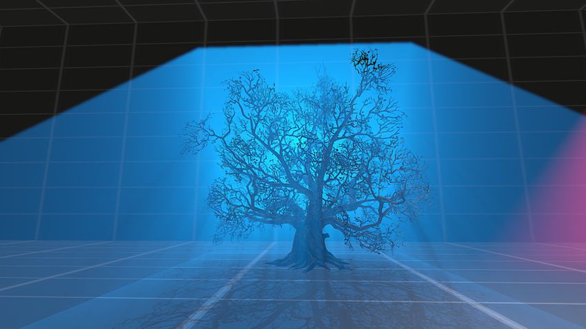
Who are we?
                                         •   One of Germany’s leading game studios

                                         •   Currently working on “Lords of the Fallen” in
                                             cooperation with CI Games

                                         •   We’re using our own proprietary multi-platform
                                             technology called “Fledge”

                                         •   We’ve shipped numerous titles primarily on PC but also
                                             on Xbox 360, iOS and PS3 (maybe you know Jack
                                             Keane, Ankh, Venetica, Blood Knights or Tiger and
                                             Chicken)

Let’s begin with a short introduction of our company. Deck13 Interactive is one of leading game developers in Germany and we’re currently working on
the action RPG “Lords of the Fallen” in cooperation with CI Games.
!
We’re using our own proprietary engine Fledge, which runs on PC, Xbox 360, iOS, PS3 and most recently Xbox One and PS4.
!
In the early days we’ve been working on adventure games like Jack Keane and Ankh - but we’ve settled over to the action RPG genre with titles like
Venetica, Blood Knights and Tiger and Chicken.
Lords of the Fallen

                                             •   Lords of the Fallen is a challenging Action-RPG for PC,
                                                 Xbox One and PlayStation 4

                                             •   Will be released fall 2014

                                             •   For an in-depth view into the rendering guts of Fledge,
                                                 visit Philips talk tomorrow

Lords of the Fallen is our biggest and most ambitious project yet and it will be released for PC, Xbox One and Playstation 4 in fall. If anyone of you enjoys
a challenge, this might be the right title for you. :)
!
Philip will be giving a talk about the Rendering Technology of Lords of the Fallen tomorrow - don’t miss out on that!
Who am I?

                                           •   Engine/Graphics Programmer since 2 years

                                           •   Mainly responsible for the GNM/PS4 version of
                                               “Fledge”

                                           •   Apart from that I'm behind everything related to
                                               physics, our software rasterisation based culling
                                               system, our IK system, …

Just a few words about myself: I’ve been over 2 years with Deck13 now and joined the team right when the work on “Lords of the Fallen” began. Since
then I’ve worked as a Graphics/Engine Programmer.
!
At the moment I’m primarily working on the GNM/PS4 version of Fledge and - of course - on any optimisations in this regard. Besides that I’ve contributed
subsystems like our software rasterisation based culling system and our character IK system. And, if I don’t have anything else on my list, I’m also the guy
who’s behind all the physics related things in the engine. :)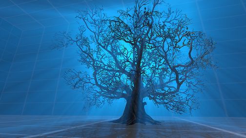
Introduction

Enough about me. Let’s cut to the chase and start with the actual topic of this talk: Volumetric Lighting.
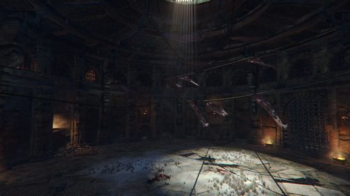
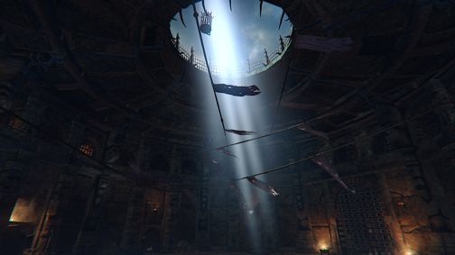
Let us begin with having a closer look at this scene. You’ll notice that the light falling through the ring in the ceiling of this arena is only noticeable on the
ground - and maybe negligibly on the surrounding walls due the bounces of our GI solution.
!
But the location itself has an all but clean look to it - everything is dusty and there is sand and rubble all over the place. There was an boss fight in here just
before I took the screenshot - so it’s most likely that there are a lot of small dust particles in the air which should allow us to perceive the light volume in
the centre of the arena at least slightly.
!
So if we bring a the Volumetric Lighting system in our engine into play here, the scene might end up looking like this:
The light travels through the thick dust particles in the air and some of the light waves get deflected into the viewer’s direction.
!
This makes the actual light volume perceivable for us. All this is caused by a phenomenon called light scattering:
Light Scattering

                                                                                                     Lightwaves

                                                                  Participating media

Given any sort of medium - take water or air as examples - there are billions of differently sized particles in there that can scatter light waves into various
directions. The light travels through the medium, gets scattered one or multiple times and - if we’re lucky - the light reaches us, the viewer.
!
The higher the overall scattering probability of the medium, the higher the probability the waves hit our retinas. And - therefore - the ticker the perceived
light volume gets. That’s for example the case if the air is filled with large dust particles or small water particles when it is foggy.
!
Let's define some general terms here: if the light reaches the viewer we’re talking about a phenomenon called in-scattering. If the light waves just leaves
the medium in some random direction it is called out-scattering. The fact that light waves can be scattered multiple times is called multiple scattering.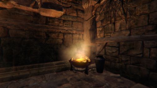
Motivation

So why did we choose to implement a Volumetric Lighting system in the first place?
Motivation

                                            •   Simple light shafts as a screen space post-processing
                                                effect [1] sure are shiny, but…

Like everyone we’ve been using the good old light shafts as a post processing effect for ages. While the effect can produce nice effects in certain cases -
like the well know crepuscular or god rays - it is very limited in almost every other case.
Light shafts as a post-processing effect Let's take a look at our intro example again. One of the main issues here is that it solely works for a single directional light source and that it only blurs the contents of the frame buffer into the direction of the light. ! If you like long light shafts, the amount of samples needed can become lethal pretty quickly. There is also no direct relation to any of the light sources in the scene and the shadow volumes produced by them. And…
Light shafts as a post-processing effect

Being a screen space effect it is obvious that if there are no bright spots visible on the screen, there won’t be any visible light shafts. That’s far from what
we wanted to achieve.
Motivation

                                          •   Billboards can be neat, but…

Sure - there are other cheating ways to achieve some basic volumetric lighting effects in games.
!
Billboards for example have been used in a lot of game productions to create a lot of very stylised Volumetric Lighting effects:
“Billboard volumetrics” Here’s a small dust billboard that fakes light scattering around this fire bowl. ! This might work well from time to time - but even if you combine billboards with sophisticated fading approaches or even add cylindrical geometry for some cases… There will be situations where the illusion breaks!
“Billboard volumetrics”

Especially if the billboards are overly large and there is no visible interaction with the objects on the screen.
Motivation

                                            •   We wanted something more dynamic and flexible that
                                                could be tightly integrated into our lighting system

                                            •   It should work with a lot of small to medium sized light
                                                sources

                                            •   Our artists tend to place a whole lot of lights

                                            •   Thus a negligible performance penalty on all
                                                supported platforms was critical

So in the end we wanted something far more dynamic and flexible that could be tightly integrated into our lighting system.
!
Since “Lords of the Fallen” will not feature too many open areas, we wanted to support a lot of small to medium sized light sources.
!
And since we knew that our artists tend to place a lot of lights, we were sure that they would most likely overuse the volumetrics once we make them
available (and trust me - our predictions were correct here). :)
!
So we needed to come up with something that wouldn’t break us the neck from a performance standpoint in the end.
State of the Art In the last year more and more games popped up on the horizon that use volumetric lighting systems.
Crysis 3
                                                  ne   4
                                           Killzo

                                                                                       Deep Down

Some of those use them mainly for their directional lights to achieve some large scale fog shadows and some other games add support for volumetric
lighting to all available light sources making them one of the main visual features.
State of the Art
• Many recent implementations seem to be based on the
work of Toth et. al. [2]:
• Ray marching in light view space while evaluating the
shadow map
• Often combined with a special sampling approach to
reduce the workload per fragment
• Many other approaches/optimisations popped up
over the recent years: Epipolar sampling [3],
sampling planes shaded in light space [4], …
Of course - we did a bit of research before we started implementing our own solution. And it seems that a lot of the recent systems are based on the work
of Toth. et. al.
!
The publication suggests the usage of ray marching while evaluating the shadow map in combination with a special sampling approach to make it feasible
for real-time applications.
!
But this is not the only available technique know today. One of the more recent publications suggest the usage of Epipolar Sampling as an optimisation
for ray marching based algorithms. One of the a tad older approaches uses actual plane geometries shaded in light space. An approach that suffers
heavily from overdraw when viewing the light sources from certain angles.Our Approach So let’s see with what we came up with…
Our Approach

                                          •   Loosely based on “Real-time Volumetric Lighting in
                                              Participating Media” (Toth et. al. [2])

                                          •   Straightforward ray marching

                                          •   Usage of “Interleaved Sampling” to reduce the overall
                                              sample count needed per fragment

                                          •   Utilises low-resolution rendering to reduce the
                                              fragment workload even further

To “keep things simple” we started our implementation based on the work of Toth et. al. and we ended up with a ray marching based approach which
samples the shadow map.
!
Since ray marching is still quite costly today - especially when executed on a full resolution RT - we use low-resolution rendering and a technique called
Interleaved Sampling to reduce the overall sample count per fragment.
Our Approach
• Works with multiple lights and light types
• Custom bilateral blurring and depth-aware up-
sampling to work around the obvious artefacts
• Various tweaks and optimisations per light type
• Completely implemented using good old pixel and
vertex shaders - no compute
The usage of low-resolution rendering and Interleaved Sampling comes not without any costs. If not addressed correctly, there are many artefacts which
destroy the visual fidelity of the end result.
!
We also added a lot of tweaks and optimisations for all the different light types supported in our engine to avoid the sampling of any unnecessary regions
on the screen.
!
And - the good news is - the complete system can be implemented without the usage of any compute shaders. But it would be interesting to do so! I
know.Basic Algorithm To keep things simple I will start with a “basic version” of the algorithm for a single directional light source.
Radiative Transport Equation [2]
                                                                                    Z
                                          dL(~x(s), !
                                                    ~)
                                                       =      ⌧ L(~x(s), !
                                                                         ~ ) + ⌧a            L(~x(s), !     !0 , !
                                                                                                      ~ )P (~    ~ )d! 0
                                               ds                                       ⌦0

                                           ~x(s) = ~x0 + !
                                                         ~ s Ray equation, where ω is the direction of the ray

                                           L(~x(s), !
                                                    ~)         Change of radiance along the ray

                                           ⌧                   Probability of collision

                                           a                   Scattering probability after collision

                                              !0 , !
                                           P (~    ~)          Phase function

The whole approach is based on the so called “Radiative Transport Equation” which can be used to evaluate the change of radiance along a ray
throughout participating media.
!
One of the most important properties of this equation are the variables “tau” and “a”, the albedo which describe the overall scattering probability and
thus the resulting thickness of the simulated light volume.
!
Plugging in a phase function allows the usage of anisotropic scattering.
!
This integro-differential equation is hard to solve - even in combination with Monte Carlo approaches for offline renderers… Anyhow - it’s far too slow for
real-time rendering.
Ignore multiple scattering
Z s
⌧s ⌧ (s l)
L(~x(s), !
~) = e L(~x0 , !
~) + Li (~x(l), !
~ )e dl
0
N
X
⌧s ⌧ (s ln )
~ ) ⇡ L(~x0 , !
L(~x(s), ! ~ )e + Li (~x(ln ), !
~ )e l
n=0
⌧d
Li (~x, !
~ ) = ⌧a v(~x)e P (~ ~ ) In-scattering term
!l , !
4⇡d2
s Total ray marching distance v(~x) Visibility function
d Distance to the light source Source power of the light
l Step size Direction from the
!
~l ray position to
l Traveled distance on the ray the light source
Luckily it can be simplified if we assume that there is no multiple scattering in our small, limited world. The resulting integral equation can be analytically
approximated using a Riemann Sum and thus finally evaluated using ray marching.
!
So we end up marching along the ray in direction “omega” in steps of size “delta l” while evaluating the incident radiance “Li”.
!
The incident radiance function is mostly fed with constants like the power of the light source “Phi” and the parameters I’ve mentioned earlier that
describe the scattering probability.
!
But it also evaluates the visibility term “v(x)”. This function returns zero if the point on the ray is occluded from the light’s perspective and one if not.
!
We’ll ignore the phase function for the time being since the system can be very well implemented with without anisotropic scattering and it might
overcomplicate things in the beginning.Basic Algorithm
• Let’s start with a simple
fullscreen pass for a
directional light
• Start the ray marching on the
position of the current
fragment in light space
• Evaluate and accumulate the
in-scattering term for each of
the n samples and march in
equidistant steps towards the
position of the viewer
Let’s see how we bake the previous two slides into some actual shader code.
!
We’ll begin with a simple fullscreen pass where we start the actual ray marching on the position of the current fragment. The position has to be in light
space so it is possible to evaluate the visibility term using the shadow map without any additional calculations.
!
So - as you do it with any sorts of deferred renderer - you end up reconstructing the world position from depth and multiplying it by the view matrix of the
light frustum. From there on on we evaluate the incident radiance, travel another small step into the direction of the viewer, add it to the total contribution
and repeat those steps until we reach our destination.#define NUM_SAMPLES 128!
#define NUM_SAMPLES_RCP 0.0078125!
!
FRAGMENT_OUT ps_main(VERTEX_OUTPUT f_in)!
{!
// Fallback if we can't find a tighter limit!
float raymarchDistanceLimit = 999999.0 ;!
!
[...]!
!
// Reduce noisyness by truncating the starting position!
float raymarchDistance = trunc ( clamp ( length ( cameraPositionLightVS . xyz - positionLightVS . xyz ) , !
0.0, raymarchDistanceLimit ) ) ;!
!
// Calculate the size of each step!
float stepSize = raymarchDistance * NUM_SAMPLES_RCP ;!
float3 rayPositionLightVS = positionLightVS . xyz ;!
!
// The total light contribution accumulated along the ray!
float3 VLI = 0.0 ;!
!
// ... start the actual ray marching!
[loop] for ( float l = raymarchDistance; l > stepSize ; l -= stepSize ) !
{!
executeRaymarching(...) ;!
}!
!
f_out . color . rgb = light_color_diffuse . rgb * VLI ;!
return f_out ;!
}
Here’s a “small” excerpt showing some of the more interesting parts of the actual shader source.
!
First - we setup some constants and calculate the actual distance we have to march into the direction of the viewer.
!
We ended up truncating the starting position to avoid artefacts caused by precisions issues when moving the camera ever so slightly. From there on on we
execute the actual ray marching steps until we reach the position of the viewer.
!
We encapsulated the ray marching into a separate function so we could easily manually unroll the loop for GCN GPUs - four manual inner iterations per
outer iteration worked out well for us.#define TAU 0.0001!
#define PHI 10000000.0!
!
#define PI_RCP 0.31830988618379067153776752674503!
!
void executeRaymarching(...)!
{!
rayPositionLightVS . xyz += stepSize * invViewDirLightVS . xyz ;!
!
[...]!
!
// Fetch whether the current position on the ray is visible form the light's perspective - or not!
float3 shadowTerm = getShadowTerm ( shadowMapSampler, shadowMapSamplerState, rayPositionLightSS . xyz ) . xxx ;!
!
// Distance to the current position on the ray in light view-space!
float d = length ( rayPositionLightVS . xyz ) ; ;!
float dRcp = rcp ( d ) ;!
!
// Calculate the final light contribution for the sample on the ray...!
float3 intens = TAU * ( shadowTerm * (phi * 0.25 * PI_RCP) * dRcp * dRcp ) * exp( -d * TAU ) * exp ( -l * TAU ) *
stepSize ;!
!
// ... and add it to the total contribution of the ray!
VLI += intens ;!
}
For each ray marching step we project the current position on the ray into light projection space and evaluate the shadow term as we always do.
!
From here on on we can finally calculate the volumetric lighting intensity as I’ve described before and add it to the total volumetric lighting contribution.
!
The only difference here is that I’ve left out the phase function to keep things simple.So - if you’ve done everything correctly and you’ve chosen a generous amount of samples, you might end up with something like this.
From One to Many

Now comes the fun part. As I’ve explained before, we wanted something more flexible that can be used with a fair amount of light sources on the screen
and with various light types.
As you can see here we moved the “global” approach using the simple fullscreen pass to multiple smaller passes tightly bound to the actual light type and
the underlying light volume geometry of our deferred renderer.
We’re currently supporting non-shadow casting point lights as well as shadow casting spot and box lights for volumetrics. Box lights are more or less the
lightweight variant of our large scale PSSM based main light.
From One to Many
                                           •   Render the back faces of the
                                               light volume for each
                                               volumetric light (depth test/
                                               write disabled)

                                           •   Start the ray marching on the
                                               fragment of the light geometry
                                               instead of the scene geometry

                                           •   If the light volume intersects
                                               the scene geometry, the
                                               starting position gets clamped
                                               to the closest fragment
                                               position relatively to the
                                               viewer

Let’s see how we can extend the basis system to work with multiple light sources on the screen. The idea is quite simple and very easy to implement -
especially if you’re already using a deferred renderer.
!
We start by rendering the actual light geometry like we do for our lighting pass. And instead of starting the ray marching on the scene geometry, we start
the marching on the light volume’s current fragment world position.
!
You have to be careful if the light volume intersects the scene geometry - in this case you can easily “clamp” the position to the scene geometry’s position.
Otherwise you will end up evaluating the lighting contribution for parts of the screen that are not actually visible and any occlusion will end up looking
broken.
From One to Many
• Calculate the in-scattering term as depicted before
• In addition to that evaluate the attenuation function for each
given light type and “modulate” it with the in-scattering
term
• March the ray in light view and in world space in parallel -
less costly than transforming between spaces for each step
• Accumulate the volumetric lighting contribution for each
visible light to an accumulation buffer using additive
blending
The in-scattering term can be evaluated exactly the same way as before - but this time we also “modulate” it with the attenuation function of our spot,
point and box lights. The attenuation function will make sure that there is a zero contribution for any positions on the ray outside the light volume.
!
Since we’re only marching in light view space yet, you can just march the ray a second time in parallel in world space . Instead of “transforming” it to a
different space on the fly all the time.
!
We accumulate all lights to a special render target we call the accumulation buffer. Like for normal lights, we can just additively blend all the light on top of
each other without keeping any special ordering in mind.From One to Many
• Constrain the taken samples to the area inside the
light volume to increase the precision
• For box and point lights we simply clamp the total ray
marching distance to the attenuation ranges of the
lights
• In the case of spotlights we actually calculate the
intersection points between the current ray and the
light volume and calculate the range in-between
We did some special optimisations for each of the light types.
!
First of all for box and point lights we discard any starting positions that are outside the light volumes in the first place.
!
To increase the precision we limit the total ray marching distance roughly to the attenuation ranges of the lights.
!
Spot lights can be quite tricky due to the small radii near their origins. In this cases we’re actually calculating the intersection points between the light
volume and the ray and measure the distance in-between those. This allows to achieve a more or less uniform distribution of samples in all the areas of the
cone. Of course we also reject any starting position outside of the cone.How to Make it Fast
Much slow So sample
Wow
Sadly… everything I told you so far is far from bring feasible for many light sources in a real-time context.How to Make it Fast
• Everything I told you so far needs far too many
samples to achieve visually pleasing results
• 128+ samples per fragment for each light rendered to a
full resolution target does not sound like the ideal
solution
So the actual problems are the following…
!
First of all we need far to many samples and the fact that everything happens in full resolution for multiple lights doesn’t actually help. We need even
more samples when evaluating the shadows of some detailed object like a tree with a lot of tiny leaves.
!
Okay, looks like we’re lost… right?How to Make it Fast
• We ended up rendering all volumetrics to a half or
quarter resolution target
• We use an additional depth aware up-sampling pass
to hide this fact - often referred to as ”Nearest Depth
Up-Sampling“ [5]
The first trick we applied is to move the volumetric light accumulation pass to a half or quarter resolution render target. This will - of course - increase the
performance, but it will also introduce the low-resolution rendering typical artefacts if not treated correctly.
!
The trick is to use an additional up-sampling pass that uses the native resolution depth buffer as well as a low-resolution depth buffer to apply a technique
called nearest depth up-sampling.Without depth-aware up-sampling In this example the low-resolution accumulation buffer is blended over the scene. This introduces some very noticeable artefacts at the edges of the full resolution geometry. In some bad cases the whole scene might appear to be renderer to a half or quarter resolution render target.
With depth-aware up-sampling

If we add the additional up-sampling pass using nearest depth up-sampling the problem goes away. The low resolution render target gets perfectly
blended over the scene while keeping the crisp edges of the geometry.
How to Make it Fast

                                         •   Only using half-resolution rendering will not suffice to
                                             make it fast enough for multiple light sources on the
                                             screen

                                         •   We can “abuse” the fact that the in-scattered light
                                             value at a given fragment position is either equal or at
                                             least close to one or more of the surrounding values

Okay - even using low-resolution rendering we’re not quite there yet. Even in half resolution 128+ samples per light can drive any modern GPU to its
limits.
!
Why don’t we abuse the fact the volumetric lighting information for a given fragment doesn’t differ drastically when compared to the surrounding
fragments?
How to Make it Fast
• We spread the evaluation of vs.
the in-scattering term from a
single pixel to multiple pixels
• We ended up using 8x8 pixel
tiles, where each pixel of a
tile evaluates 16 samples
• This makes a total of 8x8x16
= 1024 potential samples
• Each pixel of one tile
evaluates a different region of
the ray
This is the part where “Interleaved Sampling” comes into play. I’ve heard some people refer to it as a dithering technique and this comes pretty close to
what it actually is.
!
The general idea is to spread the calculation from a single pixel to multiple pixels. So instead of evaluating 128 samples per pixel, we evaluate 128 pixels
per NxN pixel tile.
!
We ended up using 8x8 pixel tiles where each pixel only has to evaluate 16 samples. This results in a total of 1k potential samples - which is even more
than the slow 128 samples we used in the first place.
!
Since the evaluation of the whole ray is spread across all pixels of the 8x8 tile, each pixel of one tile has to evaluate a different region of the ray.How to Make it Fast
• Assign an unique index i ∊ [0..64) to each pixel of the tile
- the indices repeat for each tile
• Reduce the total ray marching distance by one step
• Offset the ray marching starting position for each pixel of
the tile according to i
stepSize
• ray = i
64
• Randomising the indices trades the obvious repetitive
sampling pattern for some less noticeable noise
But how do we spread the samples across the tile? The simplest idea is just to assign an unique index in the range [0…63] to each pixel of one tile and
offset the ray starting position in relation to the total amount of samples involved and the total ray marching distance.
!
This approach will result in a noticeable repetitive sampling pattern. We ended up randomising the indices we assign to each tile which replaces the
repetitive sampling pattern with some less noticeable continuos noise.#define INTERLEAVED_GRID_SIZE 8!
#define INTERLEAVED_GRID_SIZE_SQR 64!
#define INTERLEAVED_GRID_SIZE_SQR_RCP 0.015625!
!
[...]!
!
// Calculate the offsets on the ray according to the interleaved sampling pattern!
float2 interleavedPos = fmod ( f_in . position . xy, INTERLEAVED_GRID_SIZE ) ; !
!
#if defined (USE_RANDOM_RAY_SAMPLES)!
float index = ( interleavedPos . y * INTERLEAVED_GRID_SIZE + interleavedPos . x ) ;!
// light_volumetric_random_ray_samples contains the values 0..63 in a randomized order!
// The indices are packed to float4s => { (0,1,2,3), (4,5,6,7), ... }!
float rayStartOffset = light_volumetric_random_ray_samples [ index * 0.25 ] [ fmod ( index, 4.0 ) ] * ( stepSize *
INTERLEAVED_GRID_SIZE_SQR_RCP ) ;!
#else!
float rayStartOffset = ( interleavedPos . y * INTERLEAVED_GRID_SIZE + interleavedPos . x ) * ( stepSize *
INTERLEAVED_GRID_SIZE_SQR_RCP ) ;!
#endif // USE_RANDOM_RAY_SAMPLES!
!
float3 rayPositionLightVS = rayStartOffset * invViewDirLightVS . xyz + positionLightVS . xyz ;!
!
[...]
Here’s what we’re doing in the background… For each pixel of the full screen pass we calculate the current index of the pixel inside the current tile and
either use it directly to offset the ray starting position...
!
...or we use it to perform a lookup from the randomised indices we prepared on the CPU beforehand.
!
The distance we have to offset the ray can be easily calculate by dividing the “global step size” by the total amount of pixels per tile.Accumulation buffer before the gather pass If everything turned out right, we end up with something like this. This result is from an accumulation pass into a quarter resolution render target. ! Note the repetitive pattern introduced by the 8x8 tiles. If you take a look at the part near the ground of the point light on the front left, you can actually see that each pixel evaluates a different region of the ray. Only a few pixels of the 8x8 tiles in this region actually add something to the overall volumetric lighting contribution here.
How to Make it Fast

                                           •   To achieve the final results we use an additional blur
                                               pass before the up-sampling pass

                                           •   We use a simple bilateral blur filter to avoid bleeding
                                               over the edges of any geometry inside or behind the
                                               volumetrics

It is faster now but… It looks rather strange right now, doesn’t it? So what do we do about it? We blur the hell our of it - of course!
!
In this new “Gather Pass” we’re using a Gaussian Blur with 15 samples along the horizontal and the vertical axes. To avoid that the volumetrics bleed over
the edges of any geometry inside or behind them, we added a simple bilateral filter to it.
Accumulation buffer after the gather pass This result is after blurring the results of an accumulation pass to a quarter resolution render target. As you can see that the blur pass completely eliminates the repetitive pattern while keeping the edges of the geometry alive.
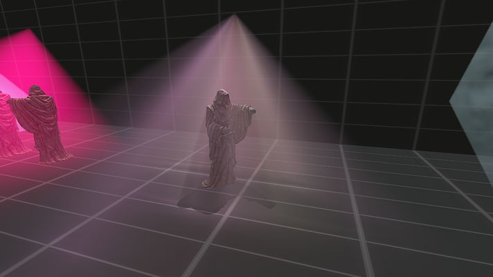
Non-bilateral blur

Let’s compare how important the bilateral filtering was in the end… Here’s an example without bilateral filtering. Note the blurry edges and halos around
the the frontmost statue.
Bilateral blur

With bilateral filtering the halos and the blurry edges get completely eliminated. Given this example you might think that the bilateral filtering is not that
important. But it depends…
Non-bilateral blur

If you end up with some very detailed objects like this tree it becomes more obvious. The volumetrics completely smudge over the fine details and
completely destroy the visual quality of the image.
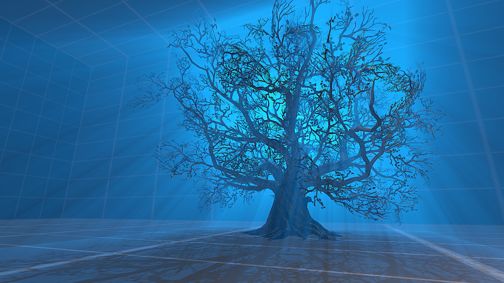
Bilateral blur

But with the bilateral filter I’ve just described you can completely work around this issue!
Render light geometry
                                                                                                               R11G11B10
                                                        for each volumetric and
                                                                                                              1/2 Resolution
                                                         execute ray marching

                                                          Accumulation Pass

                                                                                      Apply horizontal and
                                                                                        vertical bilateral     Gather Pass
                                                                                         Gaussian Blur

                                                                                     Apply depth-aware up-
                                          Final Scene                                                         Upscale Pass
                                                                                           sampling

                                                          Add final up-scaled                                  R11G11B10
                                                          buffer to the scene                                Native Resolution

                                                           Composite Pass

Let’s recap how the whole Volumetric Lighting system works.
!
First we start with the “Accumulation Pass” where we render the light geometry of each volumetric light without depth write/test and execute the ray
marching. The results for each light get additively blended. We chose to use a R11G11B10 floating point format in half resolution.
!
After that we apply the gather pass with the bilateral filter I’ve just described.
!
The results of this pass get up-scaled to native resolution using nearest-depth up-sampling.
!
Finally the resulting buffer can be blended over the final scene right before the HDR tone mapping.
Extending the System While we developed the system we came up with a lot of neat ideas that could be used to achieve different effects for various scenarios... ! ...and to work around some of the remaining artefacts.
2D projector texture (gobo/cookie)

In this example we ended up sampling an ordinary 2D texture in light projection space and modulating it with the in-scattering term.
!
This technique can be easily used to generate multicoloured light shafts and can work without sampling the shadow map at all.
!
Using UV transformations the shafts can even be animated.
3D noise texture

Here we’re sampling a 3D noise texture in world space and modulating it with the in-scattering term. This technique can be used to give the scattering a
more realistic look - especially if you’re aiming to simulate some areas with thick dust.
!
Again, if you add some simple 3D UV transformations here you can generate nice looking animated wind effects which can even replace costly particle
emitters in certain cases.
Top down perspective
                                                                                                      IES profiles

Of course the volumetrics can also be used to evaluate the soon to be famous IES profiles in a three-dimensional fashion - you’ll just have to replace or
extend the attenuation function.
Isostropic scattering Until now we’ve only looked at isotropic scattering by ignoring the phase function. This means the scattering probability is uniform in all directions.
1 g2
                                         p(⇥) =
                                                (1 + g 2 + 2g cos ⇥)1.5

                                                                                   Anisotropic scattering
                                                                       (Henyey-Greenstein phase function)

By introducing a Phase Function you can achieve anisotropic scattering. In this example we used the Henyey-Greenstein phase function to simulate Mie
scattering. The light is configured to scatter light with a higher probability into the forward direction of the light source.
1 k2
p(⇥) =
(1 + k cos ⇥)2
k ⇡ 1.55g 0.55g 3
Anisotropic scattering
(Schlick phase function)
Since the Henyey-Greenstein function can be costly to evaluate on the GPU we ended up using an approximation: the so called Schlick phase function.
The results were almost identical but we got away without the costly 1.5 exponent.Without temporal re-projection Using low-resolution rendering and the bilateral blur filter can introduce artefacts when used in combination with high-frequency 2D and 3D projector textures as well as detailed objects in the shadow map. ! The issue grows with the luminance of the volumetric light and fine details in the scene’s geometry. Notice how the whole screen flickers due to the volumetric placed in the treasury room?
With temporal re-projection

Using the temporal re-projection algorithm we were able to stabilise the volumetrics completely. The algorithm was used for example by DICE for their
SSAO in Battlefield 3.
!
The idea is to blend the results of the previous frame with the results of the current frame using the view space position as well as the luminance of the
fragments as the blend weights. This worked especially well when using a quarter resolution accumulation pass which is very prone to become noisy
quickly.
Performance

Let’s take a quick look how the system actually performs from a performance standpoint.
This scene contains a total of 7 volumetric lights in different sizes and with different features enabled. 3 of them are evaluating the shadow map, one is
evaluating a 2d texture and one is evaluating a 3d texture. Some of them use anisotropic scattering.
Pass           PC (GTX 700 Series GPU)               PS4/GNM

                                            Accumulation*             0.362 ms                       0.161 ms

                                               Gather                 0.223 ms                       0.375 ms

                                              Upscale                 0.127 ms                       0.321 ms

                                                                     = 0.712 ms                     = 0.857 ms

                                                                              *measured using a half resolution render target

On a consumer PC with a GTX 700 series GPU everything in total takes well below a millisecond to execute on the GPU. While the Gather and Upscale
passes add a constant overhead of 0.3 ms, the time needed for the accumulation pass increases with each volumetric. The time spent to accumulate one
volumetric is somewhere around 60 microseconds on average.
!
On the PS4 we achieved similar results in total. The accumulation passes per light are even faster due to the GCN specific optimisations.
!
Adding temporal re-projection to the equation adds another 10th of a millisecond on both platforms while removing almost all of the remaining artefacts.
Results To conclude this talk: Here are some results from the volumetrics in “Lords of the Fallen” in the “dusty” level I’ve showed you right at the beginning.
No volumetrics

Here's the first sample scene without volumetric lighting.
Volumetrics active

If we enable it, we see that the scene is filled with multiple volumetric spot- and point-lights.
!
Some of them simulate the light emitted from the centre of the arena throughout the grates on the left.
!
Some others are used to add the in-scattered light emitted from the firebowls, lamps and candles in the according colour of the light source.
No volumetrics

This is another sample scene. This time there is a single volumetric spot light hidden behind the statue. Let's enable the volumetrics again...
Volumetrics active

Note the tick “black” holes in the light volumes caused by the shadow map occlusion. Of course they an be used as a stylistic instrument (nice shafts were
one of the reasons we actually developed this system).
!
But in general this phenomenon is very unrealistic and mostly caused by the absence of multiple scattering. The “black holes” would be filled up by light
waves scattered from the non-occluded areas which then again get scattered to the direction of the viewer.
!
Very costly to simulate correctly, but by slightly playing around with the visibility function and by limiting the maximum amount the shadow occlusion term
can influence it, we were able to fake multiple scattering to a certain degree.
“Faked” multiple scattering

And I think the results speak for themselves!
Thanks for listening! :)
                                                      Questions?

Thank you very much for listening and... any questions?
Contact
• Benjamin Glatzel
• @begla
• http://www.deck13.comReferences
• [1] Volumetric Light Scattering as a Post-Process - http://
http.developer.nvidia.com/GPUGems3/gpugems3_ch13.html
• [2] Real-time Volumetric Lighting in Participating Media - http://
sirkan.iit.bme.hu/~szirmay/lightshaft.pdf
• [3] Epipolar Sampling for Shadows and Crepuscular Rays in Participating
Media with Single Scattering - http://www.sfb716.uni-stuttgart.de/uploads/
tx_vispublications/espmss10.pdf
• [4] Light Shafts - Rendering Shadows in Participating Media - http://
developer.amd.com/wordpress/media/2012/10/Mitchell_LightShafts.pdf
• [5] Fast Rendering of Opacity Mapped Particles using DirectX 11 Tessellation
and Mixed Resolutions - https://developer.nvidia.com/sites/default/files/akamai/
gamedev/files/sdk/11/OpacityMappingSDKWhitePaper.pdfBonus Slides
½-Resolution accumulation buffer

Half resolution accumulation buffer vs…
¼-Resolution accumulation buffer

… quarter resolution.
static const float gauss_filter_weights[] = {!
                                                0.14446445, 0.13543542, 0.11153505, 0.08055309, 0.05087564, 0.02798160, 0.01332457, 0.00545096!
                                              } ;!
                                              !
                                              #define NUM_SAMPLES_HALF 7!
                                              #define BLUR_DEPTH_FALLOFF 1000.0!
                                              !
                                              float4 gatherGauss ( in float2 blurDirection , in float2 uv )!
                                              {!
                                                 [...]!
                                              !
                                                   [unroll]!
                                                   for ( REAL r = -NUM_SAMPLES_HALF; r
float4 ps_upsample ( VERTEX_OUTPUT f_in ) : SV_Target!
{!
[...]!
!
// Better choose something relative to the far clip distance here!
const float upsampleDepthThreshold = 0.0001 ;!
!
float minDepthDiff = 1.0 ;!
uint nearestDepthIndex = 0 ;!
!
float currentDepthDiff = abs ( sampleDownsampledDepth[0] - fullResDepth ) ;!
bool rejectSample = currentDepthDiff < upsampleDepthThreshold ;!
!
[branch]!
if ( currentDepthDiff < minDepthDiff )!
{!
minDepthDiff = currentDepthDiff ;!
nearestDepthIndex = 0 ;!
}!
!
currentDepthDiff = abs ( sampleDownsampledDepth[1] - fullResDepth ) ;!
rejectSample = rejectSample && currentDepthDiff < upsampleDepthThreshold ; !
!
[branch]!
if ( currentDepthDiff < minDepthDiff )!
{!
minDepthDiff = currentDepthDiff ;!
nearestDepthIndex = 1 ;!
}!
!
// Repeat this for the remaining 2 samples!
[...]!
!
// Avoid blocky artefacts using edge detection!
if (rejectSample)!
return float4 ( SAMPLE ( inputSampler, f_in . uv0 ) . rgb, 1.0 ) ;!
!
return float4 ( sampleR[nearestDepthIndex], sampleG[nearestDepthIndex], sampleB[nearestDepthIndex], 1.0 ) ;!
}
In the mentioned separate up-sampling pass we compare four taps in the bilinear footprint of the current fragment and their according depth values in the
low-resolution render targets with the center depth of the full resolution target.
!
We chose the one of the four low resolution fragments that is closest to the full resolution depth. To avoid additional artefacts introduced by this
approach, we limit it to be only executed on the edges of the geometry using a simple edge detection algorithm.
!
This approach is a perfect candidate to be sped up by using the DX10/DX11 gather instructions.You can also read