266MST Differential pressure transmitters - ABB MEASUREMENT & ANALYTICS | DATA SHEET
←
→
Page content transcription
If your browser does not render page correctly, please read the page content below
—
ABB MEASUREMENT & ANALY TICS | DATA SHEET

266MST
Differential pressure transmitters

2          266MST DI FFER EN TI AL P R ESS UR E TR ANSMIT TE RS | DS/266MST-E N RE V. H

—
Measurement made easy
Engineered solutions for all applications

—
Base accuracy
• 0.04 % of calibrated span (optional, 0.025 %)
—
Proven sensor technology together with state–of–the–art digital
technology
• Large turn down ratio of up to 100:1
—
Comprehensive sensor selection
• Optimized overall performance and stability
—
10–year stability
• 0.15 % of URL
—
Flexible configuration options
• Local configuration via operating buttons on LCD indicator
—
New TTG (Through–The–Glass) keypad technology
• Enables quick and easy local configuration without the need to open the
  cover – even in explosion proof environments
—
IEC 61508 certification
• For SIL2– (1oo1) and SIL3– (1oo2) applications
—
Full compliance with Pressure Equipment Directive (PED) category III
—
Product in compliance with Directive 2011/65/UE (RoHS II)
—
In-built advanced diagnostics
26 6 M ST DIF F E R EN TI AL P R ESS UR E TR AN S MI T T E RS | DS/266MST-E N RE V. H                                                3

—
Specification – functional
Range and span limits
                                                                             Span limit
Sensor        Upper range limit        Lower range           Minimum            Maximum span = URL
code                     (URL)           limit (LRL)    measuring span          (can be adjusted for differential pressure transmitters up
A                         1 kPa              –1 kPa            0.05 kPa         to ± URL (TD = 0.5) within the measuring range limits)
                       10 mbar            –10 mbar             0.5 mbar
                       4 inH2O            –4 inH2O            0.2 inH2O
                                                                             NOTICE
C                         6 kPa              –6 kPa              0.2 kPa
                       60 mbar            –60 mbar               2 mbar
                                                                               To optimize performance characteristics, it is
                      24 inH2O           –24 inH2O            0.8 inH2O        recommended that you select the transmitter sensor code
F                       40 kPa              –40 kPa              0.4 kPa       with the lowest turn down ratio.
                      400 mbar           –400 mbar               4 mbar
                     160 inH2O          –160 inH2O            1.6 inH2O
                                                                             Recommendation for square root function
L                     250 kPa              –250 kPa              2.5 kPa        At least 10 % of upper measuring range limit (URL)
                    2500 mbar           –2500 mbar              25 mbar
                   1000 inH2O          –1000 inH2O             10 inH2O
N                     2000 kPa            –2000 kPa              20 kPa
                                                                             Zero position suppression and elevation
                        20 bar               –20 bar             0.2 bar        The zero position and span can be set to any value within
                       290 psi              –290 psi             2.9 psi        the measuring range limits listed in the table if:
R                    10000 kPa          –10000 kPa              100 kPa          –– adjusted span ≥ smallest span
                       100 bar             –100 bar               1 bar
                      1450 psi            –1450 psi             14.5 psi
                                                                             Damping
                                                                               Configurable time constant between 0 and 60 s.
Second sensor of the 266MST differential pressure
                                                                               This is in addition to the sensor response time.
transmitter for absolute pressure measurement
   Measuring range: 41 MPa, 410 bar, 5945 psi (2 MPa, 20 bar,
                                                                             Warm–up time
   290 psi for sensor code A)
                                                                                Ready for operation as per specifications in less than 10 s
                                                                                with minimum damping

                                                                             Insulation resistance
                                                                                > 100 MΩ at 500 V DC (between terminals and ground)
4 266MST DI FFER EN TI AL P R ESS UR E TR ANSMIT TE RS | DS/266MST-E N RE V. H
—
Specification – operative limits
Pressure limits
Overpressure limits Static pressure limits
The differential pressure transmitters, models 266MST, The differential pressure transmitters, models 266MST,
work without damage within the following pressure limits: work within the specifications with the following limit
values:
Sensors Filling fluid Overpressure limits
Sensor A Silicone oil 0.5 kPa abs., 5 mbar abs., 0.07 psia Sensors Filling fluid Static pressure limits
and 2 MPa, 20 bar, 290 psi
Sensor A Silicone oil 3.5 kPa abs., 35 mbar abs., 0.5 psia
Sensor A Inert 17.5 kPa abs., 175 mbar abs., 2.5 psia and 2 MPa, 20 bar, 290 psi
(Galden) and 2 MPa, 20 bar, 290 psi
Sensor A Inert 17.5 kPa abs., 175 mbar abs., 2.5 psia
Sensors C to R Silicone oil 0.5 kPa abs., 5 mbar abs., 0.07 psia (Galden) and 2 MPa, 20 bar, 290 psi
and 16 MPa, 160 bar, 2320 psi, or
25 MPa, 250 bar, 3625 psi, or Sensors C to R Silicone oil 3.5 kPa abs., 35 mbar abs., 0.5 psia
41 MPa, 410 bar, 5945 psi or and 16 MPa, 160 bar, 2320 psi, or
60 MPa, 600 bar, 8700 psi 25 MPa, 250 bar, 3625 psi, or
depending on code variant selected * 41 MPa, 410 bar, 5945 psi or
60 MPa, 600 bar, 8700 psi
Sensors C to R Inert 17.5 kPa abs., 175 mbar abs., 2.5 psia depending on code variant selected *
(Galden) and 16 MPa, 160 bar, 2320 psi, or
25 MPa, 250 bar, 3625 psi, or Sensors C to R Inert 17.5 kPa abs., 175 mbar abs., 2.5 psia
41 MPa, 410 bar, 5945 psi or (Galden) and 16 MPa, 160 bar, 2320 psi, or
60 MPa, 600 bar, 8700 psi 25 MPa, 250 bar, 3625 psi, or
depending on code variant selected * 41 MPa, 410 bar, 5945 psi or
60 MPa, 600 bar, 8700 psi
depending on code variant selected *
* 1 MPa, 10 bar, 145 psi for Kynar–PVDF
* 1 MPa, 10 bar, 145 psi for Kynar–PVDF
Test pressure
The pressure transmitters can withstand a pressure test
with the following line pressure without leakage:
266MST, up to 1.5 x nominal pressure (static pressure
limit) simultaneously on both sides.
Meets hydrostatic test requirements of ANSI/ISA S 82.03.26 6 M ST DIF F E R EN TI AL P R ESS UR E TR AN S MI T T E RS | DS/266MST-E N RE V. H 5
Temperature limits °C (°F)
Environment
This is the operating temperature.
Model 266MST Ambient temperature limits
Silicone oil –40 to 85 °C (–40 to 185 °F)
Inert (Galden) –40 to 85 °C (–40 to 185 °F)
Maximum operating pressure –20 to 70 °C (–4 to 158 °F)
60 MPa, 600 bar, 8700 psi
NOTICE
For applications in explosive environments, the temperature
range specified on the certificate / approval which depends
upon the type of protection sought shall apply.
Model 266MST Ambient temperature limits
Integral LCD display –40 to 85 °C (–40 to 185 °F)
Viton gasket –20 to 85 °C (–4 to 185 °F)
PTFE gaskets –20 to 85 °C (–4 to 185 °F)
It may no longer be possible to read the LCD display
clearly below –20 °C (–4 °F) and above 70 °C (158 °F).
Process
Model 266MST Process temperature limits
Silicone oil –40 to 121 °C (–40 to 250 °F) *
Inert (Galden) –40 to 121 °C (–40 to 250 °F) **
Viton gaskets –20 to 121 °C (–4 to 250 °F)
PTFE gaskets –20 to 85 °C (–4 to 185 °F)
Maximum operating pressure 60 –20 to 85 °C (–4 to 185 °F)
MPa, 600 bar, 8700 psi
* 85 °C (185 °F) for applications under 10 kPa, 100 mbar abs., 1.45 psia up
to 3.5 kPa abs., 35 mbar abs., 0.5 psia
** 85 °C (185 °F) for applications under atmospheric pressure up to 17.5
kPa abs., 175 mbar abs., 2.5 psia
Storage
Model 266MST Storage temperature range
Storage temperature –50 to 85 °C (–58 to 185 °F)
Integral LCD display –40 to 85 °C (–40 to 185 °F)
Humidity during storage
Relative humidity Up to 75 %6 266MST DI FFER EN TI AL P R ESS UR E TR ANSMIT TE RS | DS/266MST-E N RE V. H
—
...Specification – operative limits
Limits for environmental effects
Electromagnetic compatibility (EMC) EXPLOSION PROOF:
In accordance with EN 61326 and Namur NE–21 (option). • ATEX Europe (code E2) approval
Overvoltage strength in accordance with IEC 1000–4–5 EN II 1/2 G Ex db IIC T6 Ga/Gb Ta=–50 °C to +75 °C,
61000–4–5 (with overvoltage protection): 4 kV II 1/2 D Ex tb IIIC T85 °C Db Ta = –50 °C to +75 °C;
IP66, IP67.
Pressure Equipment Directive (PED) • IECEx (code E9) approval
The instruments with maximum operating pressure of 25 Ex db IIC T6 Ga/Gb Ta=–50 °C to +75 °C,
MPa, 250 bar, 3625 psi or 41 MPa, 410 bar, 5945 psi or 60 Ex tb IIIC T85 °C Db Ta = –50 °C to +75 °C; IP66, IP67.
MPa, 600 bar, 8700 psi comply with the guideline 2014/68/ • NEPSI China (code EZ)
EU category III module H. Ex d IIC T6 Gb, Ex tD A21 IP67 T85 °C.
INTRINSIC SAFETY Ex ic:
Humidity • ATEX Europe (code E3 ) type examination
Relative humidity: up to 100 %. II 3 G Ex ic IIC T6...T4 Gc, II 3 D Ex tc IIIC T85 °C Dc;
Condensation, icing: permitted. IP66, IP67.
• IECEx (code ER) type examination
Vibration resistance Ex ic IIC T6...T4 Gc, Ex tc IIIC T85 °C Dc; IP66, IP67.
Acceleration up to 2 g at frequencies of up to 1000 Hz • NEPSI China (code ES) type examination
(according to IEC 60068-2-6). Ex ic IIC T4~T6 Gc, Ex tD A22 IP67 T85 °C.
Acceleration limited to 1 g for housing out of stainless FM Approvals US (code E6) and
steel. FM Approvals Canada (code E4):
• Explosionproof (US): Class I, Division 1,
Shock resistance Groups A, B, C, D; T5
In accordance with IEC 60068–2–27 • Explosionproof (Canada): Class I, Division 1,
Acceleration: 50 g Groups B, C, D; T5
Duration: 11 ms • Dust-ignitionproof: Class II, Division 1, Groups E, F, G,
Class III, Division 1; T5
IP rating • Flameproof (US): Class I, Zone 1 AEx d IIC T4 Gb
In accordance with EN 60529, JIS C0920 • Flameproof (Canada): Class I, Zone 1 Ex d IIC T4 Gb
The transmitter is dust and sand proof and protected • Nonincendive: Class I, Division 2, Groups A, B, C, D T6...T4
against immersion effects. • Energy limited (US): Class I, Zone 2 AEx nC IIC T6...T4
• IP 67, IP 68 on request, NEMA 4X • Energy limited (Canada): Class I, Zone 2 Ex nC IIC T6...T4
• IP 65 (devices with Harting Han plug connector) • Intrinsically safe: Class I, II, III, Division 1,
• IP 66 (devices with barrel housing made from aluminum Groups A, B, C, D, E, F, G T6...T4
or stainless steel housing) Class I, Zone 0 AEx ia IIC T6...T4 (US)
Class I, Zone 0 Ex ia IIC T6...T4 (Canada)
Hazardous atmospheres Type 4X, IP66, IP67 for all above markings.
With or without integral display COMBINED FM Approvals US and Canada
INTRINSIC SAFETY Ex ia: • Intrinsically safe (code EA)
• ATEX Europe (code E1) approval COMBINED ATEX, FM and IECEx Approvals (code EN)
II 1 G Ex ia IIC T6...T4 Ga, II 1/2 G Ex ia IIC T6...T4 Ga/Gb, Technical Regulations Customs Union EAC (Russia,
II 1 D Ex ia IIIC T85 °C Da, II 1/2 D Ex ia IIIC T85 °C Da; Kazakhstan, Belarus), Inmetro (Brazil)
IP66, IP67.
• IECEx (code E8) approval The permissible ambient temperature ranges (within the
Ex ia IIC T6...T4 Ga/Gb, Ex ia IIIC T85 °C Da; IP66, IP67. limits of -50 to 85 °C) are specified in the type examination
• NEPSI China (code EY) certificates dependent upon the temperature class.
Ex ia IIC T4/T5/T6 Ga, Ex ia IIC T4/T5/T6 Ga/Gb,
Ex iaD 20 T85/T100/T135, Ex iaD 20/21 T85/T100/T135.26 6 M ST DIF F E R EN TI AL P R ESS UR E TR AN S MI T T E RS | DS/266MST-E N RE V. H 7
—
Specification – electrical data and options
HART protocol
HART® digital communication and 4 to 20 mA
HART revision 7 (standard, as default)
output
HART revision 5 (optional, on request)
Device type
Output current limits (in accordance with NAMUR standard)
1a07hex (listed at the FieldComm Group)
Overload condition
• Lower limit: 3.8 mA (configurable from 3.8 – 4 mA)
Power supply
• Upper limit: 20.5 mA (configurable from 20 – 21 mA)
The transmitter operates in an operating voltage range of
10.5 – 42 V DC with no load and is protected against
Alarm current
reversed polarity (additional loads enable operation above
42 V DC).
Adjustment range
During use in Ex ia zones and in other intrinsically safe
applications, the operating voltage must not up–scale 30 Minimum alarm current (low alarm 3.6 mA
current) (configurable from 3.6 – 4 mA)
V DC.
Maximum alarm current (high alarm 21 mA
current) (configurable from 20 – 23 mA)
Minimum operating voltage
Maximum alarm current (high alarm Limited to maximum 22 mA!
12.3 V DC Device with the option “S2 – overvoltage protection” current) for devices with “HART SIL (From electronic version 7.1.15)
10.8 V DC Devices with the option “YE – NE21 conformity” – functional safety”
Ripple Standard setting: high alarm current
Maximum 20 mV over a 250 Ω load in accordance with
HART specifications.
Load limitations
Total loop resistance at 4 to 20 mA and HART:
Supply voltage -minimum operating voltage (V DC)
R (k Ω)= ––––––––––––––––––––––––––––––––––––––––––––––––
22 mA
A minimum resistance of 250 Ω is required for HART
communication.
Overvoltage protection (optional)
Up to 4 kV
• Voltage: 1.2 µs rise time / 50 µs delay time to half the
value
• Voltage: 8 µs rise time / 20 µs delay time to half the
value
Output signal
Two–wire output 4 – 20 mA, selectable by the operator:
linear or square root output signal, characteristic curve
with the exponents 3/2 or 5/2, square root for
bidirectional flow, linearization table with 22 points (i.e.
for level measurements in lateral, cylindric containers and
spherical containers).
The HART communication provides the digital process
variables which are superimposed on the 4 to 20 mA
signal (protocol in accordance with Bell 202 FSK standard).8 266MST DI FFER EN TI AL P R ESS UR E TR ANSMIT TE RS | DS/266MST-E N RE V. H
—
...Specification – electrical data and options
FOUNDATION FieldbusTM output
DeviceType Output interface
Link–Master FOUNDATION Fieldbus digital communication protocol in
The Link Active Scheduler (LAS) capability is implemented. accordance with standard H1, fulfills the specification V 1.7
Manufacturer code: 000320 (hex)
Device type code: 0007 (hex) Operating mode during transmitter malfunction
The output signal will be “frozen” to the last value in case
Power supply of severe transmitter errors, if this is recognized by the
The transmitter works in a operating voltage area of 9 to self–diagnosis, which also shows error conditions.
32 V DC, independent of the polarity with or without In case of electronic errors or short–circuits, the current
overvoltage protection. consumption is electronically limited to a set value
During use in Ex ia zones, the operating voltage must not (approx. 20 mA) for the safety of the network.
exceed 24 V DC (object certification) or 17.5 V DC (FISCO
certification) in accordance with FF–816. Damping
Configurable time constant between 0 and 60 s.
Input Current This is in addition to the sensor response time, and can be
Operation (quiescent current): 15 mA adjusted via the optional LCD indicator, handheld
Residual current limit value 20 mA maximum terminal, or PC user interface.
Output signal Warm–up time
Physical layer in accordance with IEC 11582 / EN 611582, Ready for operation as per specifications in less than 10 s
transmission with Manchester II modulation with 31.25 with minimum damping.
kBit/s.
Insulation resistance
Function blocks / cycle time >100 MΩ at 500 V DC (between terminals and ground).
3 extended analog input blocks / 25 ms max. (each)
1 extended PID block / 40 ms max.
1 Standard Arithmetic block / 25 ms
1 Standard Input Selector block / 25 ms
1 Standard Control Selector block / 25 ms
1 Standard Signal Characterization block / 25 ms
1 Standard Integrator / Totalizer block / 25 ms
Additional blocks
1 extended Resource Block
1 manufacturer–specific Pressure with Calibration
Transducer Block
1 manufacturer–specific Advanced Diagnostics Transducer
Block with recognition of clogged impulse lines
1 manufacturer–specific local display transducer Block
Number of link objects
35
Number of VCRs
3526 6 M ST DIF F E R EN TI AL P R ESS UR E TR AN S MI T T E RS | DS/266MST-E N RE V. H 9
PROFIBUS PA output LCD display
DeviceType
Pressure transmitter conform with profile 3.0.1
Indent number: 3450 (hex)
The transmitter works in a operating voltage area of 9 to
32 V DC, independent of the polarity with or without
overvoltage protection.
During use in EEx ia zones, the operating voltage must not
exceed 17.5 V DC.
Intrinsically safe installation in accordance with the FISCO M10142
model.
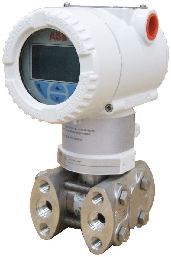
Figure 1 LCD display (example)
Input Current
Operation (quiescent current): 15 mA Integral LCD display (code L1)
Residual current limit value 20 mA maximum Wide screen LCD display, 128 x 64 pixel, 52.5 x 27.2 mm
(2.06 x 1.07 in), dot matrix, multilingual.
Output signal Four buttons for device configuration and management.
Physical layer in accordance with IEC 1158–2 / EN 61158–2, Easy setup for quick commissioning.
transmission with Manchester II modulation with 31.25 Customized visualizations which the user can select.
kBit/s. Total value and actual value flow indication.
The display can also be used to show static pressure,
Output interface sensor temperature, and diagnosis notice, as well as make
PROFIBUS PA communication in accordance with configuration settings.
PROFIBUS DP 50170 part 2 / DIN 19245 part 1–3
Integral LCD display with TTG–(Through–The–Glass)
Output cycle time operation (code L5)
25 ms As with the integral LCD display above, but featuring an
innovative TTG (Through–The–Glass) button technology
Data blocks which can be used to activate the device's configuration
266MST: and management menus without having to remove the
1 “Physical Block” transmitter housing cover.
3 “Analog Input” blocks The TTG (Through–The–Glass) buttons are protected
1 “Pressure Transducer Block” with calibration against accidental activation.
1 “Transducer Block Advanced Diagnostics” with
recognition of clogged impulse lines
1 “Transducer Block” local display
Operating mode during transmitter malfunction
In case of heavy transmitter errors, which are recognized
by self–diagnosis, the output signal can be put into
defined states, which can be chosen by the operator: safe,
most recent or calculated value.
In case of electronic errors or short–circuits, the current
consumption is electronically limited to a set value
(approx. 20 mA) for the safety of the network.10 266MST DI FFER EN TI AL P R ESS UR E TR ANSMIT TE RS | DS/266MST-E N RE V. H
—
Specification - measuring accuracy
Reference conditions in accordance with IEC 60770. Ambient temperature
Ambient temperature 20 °C (68 °F), rel. humidity 65 %, per 20 K change within the limits of –40° – 85 °C (per 36 °F
atmospheric pressure 1,013 hPa (1,013 mbar), position of change within the limits of 40° – 185 °F):
measuring cell (separating diaphragm areas) vertical,
measuring span based on zero point, separating Model Sensor For TD range
diaphragms made from stainless steel AISI 316 L or 266MST A 10:1 ±(0.06 % URL + 0.045 % span)
Hastelloy, silicone oil filling fluid, HART digital trim values C to R 10:1 ±(0.03 % URL + 0.045 % span)
equal to 4 and 20 mA span end points, linear characteristic
curve.
In the case of an ambient temperature change between
Unless otherwise stated, errors are specified as a % of the
–10 °C – 60 °C (14 to 140 °F):
span value.
Some measuring accuracy levels relating to the upper
Model Sensor For TD range
measuring range limit (URL) are affected by the current
turn down (TD); i.e., the ratio of the upper measuring 266MST A 10:1 ±(0.12 % URL + 0.05 % span)
range limit to the already set span. C to R 10:1 ±(0.06 % URL + 0.05 % span)
FOR OPTIMUM MEASURING ACCURACY, IT IS
RECOMMENDED THAT YOU SELECT THE SENSOR CODE per 10 K change within the limits of –40 to –10 °C or 60 to
WHICH WILL PROVIDE THE LOWEST TD VALUE. 85 °C (per 18 °F change within the limits of –40 to 14 °F or
140 to 185 °F):
Dynamic response (in accordance with IEC 61298–1)
Model Sensor For TD range
Sensors Time constant (63.2 % of total
step response) 266MST A 10:1 ± (0.05 % URL + 0.03 % span)
Sensors F to R 150 ms C to R 10:1 ± (0.025 % URL + 0.03 % span)
Sensor C 400 ms
Sensor A 1000 ms
Reaction time for all sensors 40 ms
Response time (total) = delay time + time constant
Measuring error
In % of calibrated span, consisting of terminal–based
non–linearity, hysteresis, and non repeatability.
In the case of fieldbus devices, SPAN refers to the analog
input function block output scaling.
Model Sensor For TD range
266MST A to R From 1:1 to 10:1 ± 0.04 %
A From 10:1 to 20:1 ± (0.04 + 0.005 x TD – 0.05) %
C From 10:1 to 30:1 ± (0.04 + 0.005 x TD – 0.05) %
F to R From 10:1 to 100:1 ± (0.04 + 0.005 x TD – 0.05) %
F to N From 1:1 to 10:1 ±0.025 % (optional)
Model Pabs sensor (second sensor for 266MST)
Range: 41 MPa, 410 bar, 5945 psi (2 MPa, 20 bar, 290 psi for
dp Sensor Code A)
266MST C to R 80 kPa, 800 mbar, 321 inH2O
A 1.2 kPa, 12 mbar, 4.8 inH2O26 6 M ST DIF F E R EN TI AL P R ESS UR E TR AN S MI T T E RS | DS/266MST-E N RE V. H 11
Model 266MST / absolute pressure sensor Long–term stability
For the entire temperature range of 125 K within the limits
Sensors C to R:
of –40 °C to 85 °C:
± 0.15 % of URL over a period of 10 years (± 0.05 % URL/
–– zero signal:
year)
For sensors C to R:
Sensor A:
40 kPa, 400 mbar, 160 inH2O
± 0.3 % of URL over a period of 10 years (± 0.2 % URL/year)
(absolute pressure sensor 41 MPa, 410 bar, 5945 psi)
For sensor A:
Total performance
2 kPa, 20 mbar, 8 inH2O
Temperature change of 28 °C (50 °F), only 266MST: up to
(absolute pressure sensor 2 MPa, 20 bar, 290 psi)
10 MPa, 100 bar, 1450 psi static pressure with base
accuracy option D1 (0.025%)
–– measuring span:
For sensors C to R:
Model Sensor For TD range Total performance
0.3 MPa, 3 bar, 43.5 psi
(for measuring error 0.04%)
(absolute pressure sensor 41 MPa, 410 bar, 5945 psi)
266MST F to N 1:1 ± 0.119 % of calibrated span
For sensor A:
15 kPa, 150 mbar, 60 inH2O
In the area of –10 to 60 °C (14 to 140 °F), temperature
(absolute pressure sensor 2 MPa, 20 bar, 290 psi)
changes (DIN 16086), only 266MST: up to 10 MPa, 100 bar,
1450 psi static pressure with base accuracy option D1
Static pressure
(0.025 %)
(zero signal errors can be calibrated under operating
pressure) for operating pressure up to 60 MPa, 600 bar,
Model Sensor For TD range Total performance
8700 psi
(for measuring error 0.04%)
266MST F to N 1:1 ± 0.121 % of calibrated span
Measuring Sensor A Sensors C, F, L, N Sensor R
range
The specification of total performance includes:
Zero signal Up to 2 bar: Up to 100 bar: Up to 100 bar:
error 0.05 % URL 0.05 % URL 0.1 % URL • the measuring error (non linearity including hysteresis
> 2 bar: 0.05 % > 100 bar: 0.05 % > 100 bar: 0.1 %
and non repeatability),
URL/100 bar URL/100 bar • the thermal change of the ambient temperature to zero
Span error Up to 2 bar: Up to 100 bar: Up to 100 bar: signal and measuring span
0.05 % span 0.05 % span 0.1 % span • the influence of the static pressure (only for 266MST)
> 2 bar: 0.05 % > 100 bar: 0.05 % > 100 bar: 0.1 % on the measuring span, influence on zero signal
Span/bar Span/100 bar Span/100 bar corrected after commissioning.
EMperf = √ (E∆Tz + E∆Ts)2 + E∆Ps 2 +Elin 2
Power supply
Within the limit values for the voltage / load, the total
EMperf = Total Performance
influence is less than 0.005 % of the upper measuring
E∆Tz = Effect of the ambient temperature on the zero signal
range limit values per volt.
E∆Ts = Effect of the ambient temperature on the measuring
span
Load
E∆Ps = Effect of the static pressure on the measuring span
Within the load / voltage limits, the total influence is
(only 266MST)
negligible.
Elin = Measuring error
Electromagnetic field
Meets all requirements of EN 61326 and NAMUR NE–21
(optional).
Common–mode interference
No influence from 100 V rms @ 50 Hz, or 50 V DC
Mounting position
Rotations in the plane of the diaphragm have a negligible
effect. A tilt from the vertical of up to 90° causes a zero
point shift of up to 0.35 kPa (3.5 mbar, 1.4 inH2O), which
can be corrected by making an appropriate zero position
adjustment. There is no effect on the measuring span.12 266MST DI FFER EN TI AL P R ESS UR E TR ANSMIT TE RS | DS/266MST-E N RE V. H
—
Specification – physical
(Refer to ordering information sheets for variant availability Plates
related to specific model or versions code) • Transmitter name plate: Stainless steel AISI 316
fastened to the electronics housing.
Materials • Certification plate and optional measuring point tag
Process separating diaphragms (1) plate / settings plate: Adhesive, fastened to the
Stainless steel 1.4435 (AISI 316L) electronics housing or stainless steel AISI 316L fastened
Hastelloy C276, Monel 400; Monel 400, gold plated; to the electronics housing with rivets or screws.
tantalum • Optional tag plate with customer data:
Stainless steel AISI 316L.
Process flanges, adapters, screw plugs, and vent / drain
valves * The metal plates are laser engraved, the adhesive signs
Stainless steel 1.4404 / 1.4408 (AISI 316L) thermo–printed.
Hastelloy C276; Monel 400; Kynar For stainless steel housings AISI 316L, the order option I2
(flange made of stainless steel AISI 316L with PVDF insert) or I3 must be selected for plates made from stainless steel
AISI 316.
Sensor filling fluid
Silicone oil, inert fill (Galden) Calibration
Standard: 0 to measuring range upper limit, for ambient
Mounting bracket ** temperature and atmospheric pressure
Galvanized C steel with chromium passivation; stainless Optional: To specified measuring span
steel AISI 316L.
Seals *
Viton (FPM); Buna (NBR); EPDM; PTFE or FEP–coated Viton
(only for PVDF Kynar process connection); graphite
Pressure sensor housing
Stainless steel 1.4404 (AISI 316L)
Screws and nuts
Screws and nuts made from stainless steel AISI 316, class
A4 70 or class A2–70 as per UNI 7323 (ISO 3506) in
compliance with NACE MR0175 Class II
Electronics housing and cover
Aluminum alloy (copper content ≤ 0.3 %) with baked epoxy
finish (color RAL 9002); stainless steel AISI 316L.
Cover O–ring
Buna N (Perbunan)
Operating element for local zero point, measuring span, and
write protection settings
Non–intrusive design (removable) made of glass fiber
reinforced polypropylene oxide.
* Wetted parts of the transmitter.
** U-bolt material: Stainless steel AISI 400.
Screw material: high-strength alloy steel or stainless steel AISI 316.26 6 M ST DIF F E R EN TI AL P R ESS UR E TR AN S MI T T E RS | DS/266MST-E N RE V. H 13
Optional extras Electrical connections
Mounting bracket Two 1/2–14 NPT or M20 x 1.5 tap holes for cable glands,
For vertical and horizontal 60 mm (2 in) pipes or wall directly on the housing.
mounting Special communication connector (on request)
• HART: Straight or angled Harting Han 8D plug with a
LCD display mating plug.
Rotatable in 4 positions in 90° steps • FOUNDATION Fieldbus, PROFIBUS PA: plug M12 x 1 or
7/8 in.
Additional tag plates
Code I2: For measuring point tagging (up to 30 symbols) Terminals
and calibration specifications (up to 30 symbols: lower HART–Version: Three connections for signal / external
and upper value plus unit), fastened to the transmitter display, for wire cross–sections up to 2.5 mm2 (14 AWG)
housing. and connection points for inspection and communication
Code I1: For customer data (4 lines at 30 symbols each), purposes
wired to the transmitter housing Fieldbus versions: Two signal connections (bus
connection) for wire cross–sections up to 2.5 mm2
Overvoltage protection (14 AWG)
• Code S2
Grounding
Cleaning stage for oxygen application (O2) There are internal and external ground terminals available
Code P1 for 6 mm2 (10 AWG) wire cross–sections.
Certificates (inspection, implementation, characteristics, Mounting position
material certificate) The transmitters can be installed in any position.
Code Cx and Hx The electronic housing can be rotated into any position.
A stop is provided to prevent overturning.
Name plate and operating instruction language
Code Tx and Mx Weight
(without options)
Communication plug connector Approximately 3.7 kg (8.2 lb); add 1.5 kg (3.3 lb) for
Code Ux stainless steel housing.
Add 650 g (1.5 lb) for packaging
Valve manifold installation
Code A1: Factory installation and pressure test of the ABB Packaging
Carton with dimensions of approx. 28 x 23 x 24 cm
M26 valve manifold.
(11 x 9 x 9 in)
Process connections
Flanges: 1/4–18 NPT on the process axis
Adapters: 1/2–14 NPT on the process axis
Center distance (266MST):
54 mm (2.13 in) between flanges; 51 mm, 54 mm, or
57 mm (2.01 in, 2.13 in, or 2.24 in) between adapters
Fastening screw threads:
7/16–20 UNF with 41.3 mm center distance;
only for process flange code C:
M10 with operating pressures of up to 16 MPa, 160 bar,
2320 psi or
M12 with higher operating pressures of up to 41 MPa,
410 bar, 6000 psi14 266MST DI FFER EN TI AL P R ESS UR E TR ANSMIT TE RS | DS/266MST-E N RE V. H
—
Specification – configuration
Transmitter with HART communication and 4 Transmitter with PROFIBUS PA communication
to 20 mA Standard configuration
Standard configuration The transmitters are calibrated in the factory to the
The transmitters are calibrated in the factory to the measuring range specified by the customer. The calibrated
measuring range specified by the customer. The calibrated area and the tag number are written on the name plate. If
area and the tag number are written on the name plate. this data was not specified, the transmitter is delivered
If this data was not specified, the transmitter is delivered with unlabeled plate and the following configuration:
with unlabeled plate and the following configuration:
Configuration
Configuration Measuring profile Designation of gas connections
Physical unit kPa Physical unit kPa
4 mA Zero Output scaling 0 % Measuring range lower limit (LRL)
20 mA Upper measuring range limit (URL) Output scaling 100 % Upper measuring range limit (URL)
Output Linear Output Linear
Damping 1s Upper alarm limit Upper measuring range limit (URL)
Operating mode during High alarm Upper warning limit Upper measuring range limit (URL)
transmitter malfunction
Lower warning limit Measuring range lower limit (LRL)
Software tag (max. 8 characters) Free
Lower alarm limit Measuring range lower limit (LRL)
Opitional LCD display PV in kPa; output in mA and in
Hysteresis limit value 0.5% of output scaling
percent as bargraph
PV filter time 0s
Address (set via local 126
Individual or all of the above mentioned configurable
operating buttons)
parameters, including lower range value and upper range
Long Tags 30 alphanumeric characters
value (in the same unit of measurement), can easily be
Opitional LCD display PV in kPa; output in percent as
changed with a portable HART Handheld terminal or with
bargraph
the PC configuration software with the DTM for 266
models.
Individual or all of the above mentioned configurable
The specifications for flange type and materials, materials
parameters, including the measuring range values (in the
of the O–rings and the vent / drain valves as well as other
same unit of measurement), can easily be changed with
device options are saved in the transmitter database.
the PC configuration software with the DTM for 266
models.
Customer specific configurations (option N6)
The specifications for flange type and materials, materials
The following data can be specified in addition to the
of the O–rings and the vent / drain valves as well as other
standard configuration parameters:
device options are saved in the transmitter data bank.
Description: 16 alphanumeric characters
Supplementary information: 32 alphanumeric characters
Customer specific configurations (option N6)
Date: Day, month, year The following data can be specified in addition to the
standard configuration parameters:
Pa, kPa, MPa Description: 32 alphanumeric characters
inH2O @ 4 °C, mmH2O @ 4 °C, psi Supplementary information: 32 alphanumeric characters
inH2O @ 20 °C, ftH2O @ 20 °C, mmH2O @ 20 °C Date: Day, month, year
inHg, mmHg, Torr
g/cm2, kg/cm2, atm
mbar, bar
These and others are available for PROFIBUS PA and
FOUNDATION Fieldbus.26 6 M ST DIF F E R EN TI AL P R ESS UR E TR AN S MI T T E RS | DS/266MST-E N RE V. H 15
Transmitter with FOUNDATION Fieldbus
communication
Standard configuration
The transmitters are calibrated in the factory to the
measuring range specified by the customer. The calibrated
area and the tag number are written on the name plate. If
this data was not specified, the transmitter is delivered
with unlabeled plate and the analog input function block
FB1 is configured as follows:
Configuration
Measuring profile Designation of gas connections
Physical unit kPa
Output scaling 0 % Measuring range lower limit (LRL)
Output scaling 100 % Upper measuring range limit (URL)
Output Linear
Upper alarm limit Upper measuring range limit (URL)
Upper warning limit Upper measuring range limit (URL)
Lower warning limit Measuring range lower limit (LRL)
Lower alarm limit Measuring range lower limit (LRL)
Hysteresis limit value 0.5% of output scaling
PV filter time 0s
Long Tags 30 alphanumeric characters
Optional LCD display PV in kPa; output in percent as bargraph
The analog input function blocks FB2 and FB3 are each
configured for the sensor temperature measured in °C and
the static pressure measured in MPa. Individual or all of the
above mentioned configurable parameters, including the
measuring range values, can be changed with every
FOUNDATION Fieldbus compatible configurator.
The specifications for flange type and materials, materials
of the O–rings and the vent / drain valves as well as other
device options are saved in the transmitter data bank.
Customer specific configurations (option N6)
The following data can be specified in addition to the
standard configuration parameters:
Description: 32 alphanumeric characters
Supplementary information: 32 alphanumeric characters
Date: Day, month, year16 266MST DI FFER EN TI AL P R ESS UR E TR ANSMIT TE RS | DS/266MST-E N RE V. H
—
Dimensions
(not design data) – dimensions in mm (inch)
Space for removing
Settings Name plate the cover 29 (1.14)
18 (0.71) 56 (2.21) 53 (2.09) 18 (0.71)
91 (3.58)
9 (0.35
LCD-display
housing cover
Connection side Electronic unit
145 (5.70)
179 (7.02)
210 (8.28)
Certification plate
60 (2.36) With screw plug
41.3 (1.63)
72 (2.83) With vent /
drain valve
Vent- / drain valve
65 (2.53)
12 (0.47)
Process connection
1)
Process flange
142 (5.59) adapter
90 (3.54) 33
(1.30)
M10019-01
Figure 2: Transmitter with barrel housing - horizontal flanges
(*) 54 (2.13) mm (inch) over 1/4 – 18 NPT process flange
51 (2.01), 54 (2.13) or 57 (2.24) mm (inch) over 1/2 – 14 NPT adapter flange;
Note: process connection and gasket groove comply with IEC 61518 screw threads for adapter flange or other components (e.g. valve manifold
etc.) on the process flange 7/16 – 20 UNF26 6 M ST DIF F E R EN TI AL P R ESS UR E TR AN S MI T T E RS | DS/266MST-E N RE V. H 17
29 (1.14)
18 (0.71) 56 (2.21) 53 (2.09) 18 (0.71)
91 (3.04)
179 (7.02)
210 (8.28)
60 (2.36) With screw plug
72 (2.83) With vent / drain valve
12 (0.47)
72 (2.83)
89 (3.48)
45 (1.77) 33 (1.30)
(*) 107 (4.21)
116 (4.57)
142 (5.59) 29 (1.14)
91 (3.58) 18 (0.71) 56 (2.21) 53 (2.09) 18 (0.71)
179 (7.02)
210 (8.28)
60 (2.36) With screw plug
72 (2.83) With vent / drain valve
12 (0.47)
45 (1.77) 33 (1.30)
(*) 72 (2.83)
142 (5.59) 107 (4.21)
123 (4.86)
M10020
Figure 3: Transmitter with mounting bracket, for vertical or horizontal mounting on 60 mm (2 in) pipe
(*) 54 (2.13) mm (in) via 1/4 – 18 NPT process flanges
51 (2.01), 54 (2.13), or 57 (2.24) mm (in) via 1/2 -–14 NPT adapter flanges.
Note: Process connection and gasket groove comply with IEC 61518. Thread for attaching adapter flanges or other components (e.g., manifold)
to process flange: 7/16 – 20 UNF.18 266MST DI FFER EN TI AL P R ESS UR E TR ANSMIT TE RS | DS/266MST-E N RE V. H
—
...Dimensions
... (not design data) – dimensions in mm (inch)
29 (1.14)
(*) 18 (0.71)
178 (6.99)
180 (7.08)
129 (5.06)
107 (4.21)
18 (0.71)
72 (2.83)
116 (4.57) 86 (3.40)
185 (7.25) 53 (2.09)
142 (5.59)
29 (1.14)
18 (0.71)
15 (0.57)
65 (2.54)
83 (3.28)
18 (0.71)
86 (3.40)
(*)
116 (4.57) 53 (2.09)
185 (7.25)
136 (5.35) M10021
Figure 4: Transmitter with DIN aluminum housing - horizontal flanges with mounting bracket for vertical or horizontal mounting on 60 mm (2 in) pipe
(*)54 (2.13) mm (in) via 1/4 – 18 NPT process flanges
51 (2.01), 54 (2.13), or 57 (2.24) mm (in) via 1/2 – 14 NPT adapter flanges.
Note: Process connection and gasket groove comply with IEC 61518. Thread for attaching adapter flanges or other components (e.g., manifold)
to process flange: 7/16 – 20 UNF.
Optional plug connectors26 6 M ST DIF F E R EN TI AL P R ESS UR E TR AN S MI T T E RS | DS/266MST-E N RE V. H 19
29 (1.14)
18 (0.71) 56 (2.21) 53 (2.09) 18 (0.71)
91 (3.58)
179 (7.02)
210 (8.28)
60 (2.36) With screw plug
72 (2.83) With vent /
drain valve
12 (0.47)
(*)
118 (4.63)
45 (1.77) 33 (1.30)
70 (2.75)
49 (1.93)
25 (0.98)
70 (2.75) 44 (1.71)
142 (5.59)
89 (3.48)
M10022
Figure 5: Transmitter with flat bracket, for vertical or horizontal mounting on 60 mm (2 in) pipe20 266MST DI FFER EN TI AL P R ESS UR E TR ANSMIT TE RS | DS/266MST-E N RE V. H
—
Electrical connections
HART version
Remote indicator
1 2
Power source -
+
Internal ground
- termination point
+ +
+
Line load
- - External ground
termination point
Handheld communicator
Figure 6: Electrical connection – HART Version
The HART handheld terminal can be connected to any wiring termination point in the loop as long as a minimum resistance
of 250 Ω is present between handheld terminal and transmitter power supply. If it is less than 250 Ω, additional resistance
wires must be installed to enable a communication.26 6 M ST DIF F E R EN TI AL P R ESS UR E TR AN S MI T T E RS | DS/266MST-E N RE V. H 21
Fieldbus version
Internal
1 3 2 ground terminal
7/8 inch M12 x 1 3 1
Fieldbus line
2 4 4
(independent
M10007 of the polarity)
Figure 7: Plug connectors – fieldbus versions
External
ground terminal
Pin assignment (plug)
Pin number FOUNDATION Fieldbus PROFIBUS PA
1 DATA – DATA +
2 DATA + GROUND
3 SHIELD DATA –
4 GROUND SHIELD
M10024-01
Delivery scope: plug connector without mating plug Figure 8: Standard terminal block
(female connector) supplied loose.22 266MST DI FFER EN TI AL P R ESS UR E TR ANSMIT TE RS | DS/266MST-E N RE V. H
—
...Electrical connections
HART version
Barrel-housing DIN housing
17.5 (0.69)
78.5 (3.09)
187 (7.36)
213 (8.39)
138 (5.43)
29 (1.14)
87 (3.43)
(*)
141 (5.55)
M10008-01
Figure 9: Harting Han connection – HART version26 6 M ST DIF F E R EN TI AL P R ESS UR E TR AN S MI T T E RS | DS/266MST-E N RE V. H 23
—
Ordering Information
Basic ordering information model 266MST Differential Pressure Transmitter
Select one character or set of characters from each category and specify complete catalog number.
Refer to additional ordering information and specify one or more codes for each transmitter if additional options are required.
Base model - 1st to 6th characters 266MST X X X X X X X
Differential pressure transmitter, base accuracy 0.04 %
Sensor Span Limits – 7th character
0.05 and 1 kPa (0.5 and 10 mbar, 0.2 and 4 inH2O), "Vx" option is required (Notes: 1, 2) A continued
see next page
0.2 and 6 kPa (2 and 60 mbar, 0.8 and 24 inH2O) C
0.4 and 40 kPa (4 and 400 mbar, 1.6 and 160 inH2O) F
2.5 and 250 kPa (25 and 2500 mbar, 10 and 1000 inH2O) L
20 and 2000 kPa (0.2 and 20 bar, 2.9 and 290 psi) N
100 and 10000 kPa (1 and 100 bar, 14.5 and 1450 psi) R
Maximum Working Pressure – 8th character
1 MPa / 10 bar / 145 psi (Only available with Process Flanges code P) Y
2 MPa / 20 bar / 290 psi (Only available with Sensor Span Limits code A) W
16 MPa / 160 bar / 2320 psi (Not available with Sensor Span Limits code A) C
25 MPa / 250 bar / 3625 psi (Not available with Sensor Span Limits code A) Z
41 MPa / 410 bar / 5945 psi (Not available with Sensor Span Limits code A) T
60 MPa / 600 bar / 8700 psi (Not available with Sensor Span Limits code A, A
only with process connection code A)
Diaphragm Material / Fill Fluid – 9th character
AISI 316L SST (1.4435) / Silicone oil (NACE) S
Hastelloy® C-276 / Silicone oil (NACE) K
Monel 400 / Silicone oil (NACE) M
Monel 400 gold–plated / Silicone oil (NACE) V
Tantalum / Silicone oil (NACE) T
AISI 316L SST (1.4435) / Inert fluid – Galden (Suitable for oxygen applications) (NACE) A
Hastelloy® C-276 / Inert fluid – Galden (Suitable for oxygen applications) (NACE) F
Monel 400 / Inert fluid – Galden (Suitable for oxygen applications) (NACE) C
Monel 400 gold–plated / Inert fluid – Galden (Suitable for oxygen applications) (NACE) Y
Tantalum / Inert fluid – Galden (Suitable for oxygen applications) (NACE) D
Process Flanges and Adapters Material / Connection – 10th character
AISI 316L SST (1.4404 / 1.4408) / 1/4 in –18 NPT female direct (horizontal connection) (NACE) A
AISI 316L SST (1.4404 / 1.4408) / 1/2 in –14 NPT female through adapter (horizontal connection) (NACE) B
AISI 316L SST (1.4404 / 1.4408) / 1/4 in –18 NPT female direct (DIN 19213) (horizontal connection) (NACE) C
Hastelloy® C-276 / 1/4 in –18 NPT female direct (horizontal connection) (NACE) D
Hastelloy® C-276 / 1/2 in –14 NPT female through adapter (horizontal connection) (NACE) E
Monel 400 / 1/4 in –18 NPT female direct (horizontal connection) (NACE) G
Monel 400 / 1/2 in –14 NPT female through adapter (horizontal connection) (NACE) H
Kynar (PVDF) / 1/4 in –18 NPT female direct (MWP = 1 MPa) (insert on side of flange) P
AISI 316L SST (1.4404 / 1.4408) / 1/4 in –18 NPT female direct (vertical connection) (NACE) Q24 266MST DI FFER EN TI AL P R ESS UR E TR ANSMIT TE RS | DS/266MST-E N RE V. H
—
...Ordering information
...Basic ordering information model 266MST Differential Pressure Transmitter
X X X
Bolts Material / Gaskets Material – 11th character
AISI 316 SST (NACE – not exposed to H2S) / Viton (Suitable for oxygen applications) (Max. 41 MPa / 410 bar / 5945 psi) 3
AISI 316 SST (NACE – not exposed to H2S) / PTFE (Max. 25 MPa / 250 bar / 3625 psi) 4
AISI 316 SST (NACE – not exposed to H2S) / EPDM (Max. 41 MPa / 410 bar / 5945 psi) 5
AISI 316 SST (NACE – not exposed to H2S) / Perbunan 6
AISI 316 SST (NACE – not exposed to H2S) / Graphite (Max. 41 MPa / 410 bar / 5945 psi) 7
AISI 316 SST / FEP (Only available with Kynar [PVDF] process connection) T
Housing Material / Electrical Connection – 12th character
Aluminum alloy (Barrel type) / 1/2–14 NPT A
Aluminum alloy (Barrel type) / M20 x 1.5 B
Aluminum alloy (Barrel type) / Harting Han connector (General purpose only) (Note: 2) E
Aluminum alloy (Barrel type) / Fieldbus connector (General purpose only) (Note:2) G
AISI 316L SST (Barrel type) / 1/2–14 NPT (I2 or I3 required) S
AISI 316L SST (Barrel type) / M20 x 1.5 (I2 or I3 required) T
Aluminum alloy (DIN type) / M20 x 1.5 J
Aluminum alloy (DIN type) / Harting Han connector (General purpose only) (Note: 2) K
Aluminum alloy (DIN type) / Fieldbus connector (General purpose only) (Note: 2) W
AISI 316L SST (Barrel type) / Fieldbus connector (General purpose only) (Note: 2) Z
Output – 13th character
HART digital communication and 4 to 20 mA 1
PROFIBUS PA 2
FOUNDATION Fieldbus 3
HART digital communication and 4 to 20 mA, SIL2 and SIL3 certified to IEC 61508 826 6 M ST DIF F E R EN TI AL P R ESS UR E TR AN S MI T T E RS | DS/266MST-E N RE V. H 25
Additional ordering information model 266MST Differential Pressure Transmitter
XX XX XX
Accuracy
Base accuracy 0.025 % (Note: 3) D1
Vent and Drain Valve Material / Position
AISI 316L SST (1.4404) / On process axis (NACE) V1
AISI 316L SST (1.4404) / On flanges side top (NACE) V2
AISI 316L SST (1.4404) / On flanges side bottom (NACE) V3
Hastelloy® C-276 / On process axis (NACE) V4
Hastelloy® C-276 / On flanges side top (NACE) V5
Hastelloy® C-276 / On flanges side bottom (NACE) V6
Monel 400 / On process axis (NACE) V7
Monel 400 / On flanges side top (NACE) V8
Monel 400 / On flanges side bottom (NACE) V9
Explosion Protection Certification
ATEX Intrinsic Safety Ex ia E1
ATEX Explosion Proof Ex db_tb E2
ATEX Intrinsic Safety Ex ic_tc E3
FM approval (Canada) approval (XP, DIP, IS, NI) E4
FM approval (USA) approval (XP, DIP, IS, NI) E6
FM approvals (USA and Canada) Intrinsically safe EA
FM approvals (USA and Canada) Explosionproof EB
FM approvals (USA and Canada) Nonincendive EC
Combined ATEX, IECEx and FM Approvals (USA and Canada) EN
Combined ATEX Ex ia, Ex db_tc and Ex ic_tc EW
IECEx Intrinsic Safety Ex ia E8
IECEx Explosion Proof Ex db_tb E9
IECEx Intrinsic Safety Ex ic_tc ER
Combined IEC Approval Ex ia and Ex db_tb EH
Combined IEC Approval Ex ia, Ex db_tb and Ex ic_tc EI
NEPSI Intrinsic Safety Ex ia_iaD EY
NEPSI Explosion Proof Ex d_tD EZ
NEPSI Intrinsic Safety Ex ic _nA_tD ES
Combined NEPSI Ex ia_iaD and Ex d_tD EP
Combined NEPSI Ex ia_iaD, Ex d_tD and Ex ic_nA_tD EQ26 266MST DI FFER EN TI AL P R ESS UR E TR ANSMIT TE RS | DS/266MST-E N RE V. H
—
...Ordering information
...Additional ordering information for model 266MST Differential Pressure Transmitter
XX XX XX XX XX XX
Other Explosion Protection Certifications
For TR CU EAC Ex ia for Russia (incl. GOST Metrologic Approval) W1
For TR CU EAC Ex d for Russia (incl. GOST Metrologic Approval) W2
For TR CU EAC Ex ia for Kazakhstan (incl. GOST Metrologic Approval) W3
For TR CU EAC Ex d for Kazakhstan (incl. GOST Metrologic Approval) W4
For TR CU EAC Ex ia for Belarus (incl. GOST Metrologic Approval) WF
For TR CU EAC Ex d for Belarus (incl. GOST Metrologic Approval) WG
Integral LCD
With integral LCD display L1
TTG (Through The Glass) integral digital LCD display L5
Mounting Bracket Shape / Material
For pipe mounting / Carbon steel (Not suitable for AISI housing) B1
For pipe mounting / AISI 316 SST (1.4401) (Not suitable for AISI housing) B2
Flat type bracket / AISI 316 SST (1.4401) (Suitable for AISI housing) B5
Surge / Transient Protector
With integral surge / transient protector S2
Operating Instruction Language
German M1
Italian M2
Spanish M3
French M4
English M5
Portuguese MA
Russian MB
Label and Tag Language
German T1
Italian T2
Spanish T3
French T426 6 M ST DIF F E R EN TI AL P R ESS UR E TR AN S MI T T E RS | DS/266MST-E N RE V. H 27
XX XX XX XX XX
Additional tag plate
Supplemental wired–on stainless steel plate I1
Tag and certification stainless steel plates and laser printing I2
Tag, certification and supplemental wired–on stainless steel plates and laser printing I3
Configuration (units visible on type label)
Standard pressure = inH2O / psi at 68 °F N2
Standard pressure = inH2O / psi at 39.2 °F N3
Standard pressure = inH2O / psi at 20 °C N4
Standard pressure = inH2O / psi at 4 °C N5
Custom N6
Configured for HART revision 5 (Note: 4) NH
Preparation Procedure
Oxygen service cleaning, Pmax = 12 MPa (120 bar, 1740 psi) or maximum working pressure (lower value), P1
Tmax = 60 °C / 140 °F (Only available with inert fill / viton gasket)
Certificates
Inspection certificate 3.1 acc. EN 10204 of calibration C1
Inspection certificate 3.1 acc. EN 10204 of cleanliness stage C3
Inspection certificate 3.1 acc. EN 10204 of helium leakage test of the sensor module C4
Inspection certificate 3.1 acc. EN 10204 of pressure test C5
Declaration of compliance with the order 2.1 acc. EN 10204 for instrument design C6
PMI test on wetted parts CT
Approvals
Metrologic Pattern for Russia (NOT APPLICABLE WITH ANY HAZARDOUS AREA CERTIFICATION) Y1
Metrologic Pattern for Kazakhstan (NOT APPLICABLE WITH ANY HAZARDOUS AREA CERTIFICATION) Y2
Metrologic Pattern for Ukraine (NOT APPLICABLE WITH ANY HAZARDOUS AREA CERTIFICATION) Y3
Metrologic Pattern for Belarus (NOT APPLICABLE WITH ANY HAZARDOUS AREA CERTIFICATION) Y4
DNV GL approval YA
Conformity to NAMUR NE 021 (2004) YE28 266MST DI FFER EN TI AL P R ESS UR E TR ANSMIT TE RS | DS/266MST-E N RE V. H
—
...Ordering information
...Additional ordering information for model 266MST Differential Pressure Transmitter
XX XX XX
Material Traceability
Inspection certificate 3.1 acc. EN 10204 of process wetted parts with analysis certificates as material verification (Note: 5) H3
Material certificate 2.2 acc. EN 10204 for the pressure bearing and process wetted parts H4
Plug connector
Fieldbus 7/8 in (Recommended for FOUNDATION Fieldbus, supplied loose, without female plug) U1
Fieldbus M12 x 1 (Recommended for PROFIBUS PA, supplied loose, without female plug) U2
Harting Han 8D (8U), straight entry (supplied loose) U3
Harting Han 8D (8U), angle entry (supplied loose) U4
Harting Han 7D (supplied loose) U5
With cable gland M20 x 1.5 (Plastic, black, supplied loose) U8
Housing Accessories
FM26–manifold mounting, top mounted (with DIN–housings) incl. pressure test and inspection certificate 3.1 A1
Note 1: Not available with Diaphragm Material code M, V, T, C, Y, D
Note 2: Select connector with additional ordering code
Note 3: Only available with Sensor Span Limits code F, L, N
Note 4: Not available with output code 2, 3
Note 5: Minor parts with factory certificate acc. EN 10204
Standard delivery scope (changes possible with additional ordering code)
• Adapters supplied loose
• Sealing plugs for horizontal connection flanges on the process axis; not for PVDF Kynar insert or for vertical connection
flanges (no vent / drain valves)
• For standard applications (without explosion protection)
• No display, no mounting bracket, no surge protection
• Multilanguage short–form operating instruction and English labeling
• Configuration with kPa and °C units
• No test, inspection, or material certificates26 6 M ST DIF F E R EN TI AL P R ESS UR E TR AN S MI T T E RS | DS/266MST-E N RE V. H 29
Important notice
If nothing else was determined before the manufacturing, then the customer is responsible for ensuring the compatibility
of the materials of the wetted part and the filling fluid with the measuring medium by suited selection.
Coordination with NACE directives
• The labeled materials comply with the directive NACE MR0175/ISO 15156 for the application in sulfurous environments
during the oil and gas production. As different application boundaries apply for different materials, please observe the
version of the directive that is current. The materials AISI 316 / AISI 316L, Hastelloy C 276, Monel 400 also comply with the
directive NACE MR0103 for the application in sulfurous environments in oil and gas processing.
• According to NACE MR0175, materials for pressurized screws are differentiated by application:
–– in contact with sulfurous environments: screws, that can come in direct contact with sulfurous environments, e.g.
by underfloor installation or installation in dense protective enclosures
–– not in contact with sulfurous environments: screws, which are only in contact with standard, non–sulfurous
environments
The cap screw of the pressure transmitter 266MST, comply with the requirements according to NACE MR0175 for screws
that are not in contact with sulfurous environments.
Trademarks
® Buna-N is a registered trademark of DuPont Dow Elastomers.
® FOUNDATION Fieldbus is a registered trademark of FieldComm Group, Austin, Texas, USA
® HART is a registered trademark of FieldComm Group, Austin, Texas, USA
® Hastelloy is a registered trademark of Haynes International, Inc.
® PROFIBUS and PROFIBUS PA are registered trademarks of PROFIBUS & PROFINET International (PI)
® Monel is a registered trademark of Special Metals Corporation
™ FieldComm Group is a trademark of FieldComm Group, Austin, Texas, USA
™ Galden is a Montefluos trademark
™ Kynar is an Elf Atochem North America Inc. trademark
™ Viton is a DuPont de Nemours trademark30 266MST DI FFER EN TI AL P R ESS UR E TR ANSMIT TE RS | DS/266MST-E N RE V. H — Notes
26 6 M ST DIF F E R EN TI AL P R ESS UR E TR AN S MI T T E RS | DS/266MST-E N RE V. H 31
—
ABB Ltd.                                                           ABB S.p.A.
Measurement and Analytics                                          Measurement and Analytics
Howard Road St. Neots                                              Via Luigi Vaccani 4
Cambridgeshire PE19 8EU                                            22016 Tremezzina (CO)
UK                                                                 Italy
Tel: +44 (0)870 600 6122                                           Tel: +39 0344 58111
Fax: +44 (0)1480 213 339
Email: enquiries.mp.uk@gb.abb.com

ABB Inc.
Measurement and Analytics
125 E. County Line Road
Warminster PA 18974
USA
Tel: +1 215 674 6000
Fax: +1 215 674 7183

abb.com/measurement
                                                                                                        DS/266MST-EN Rev. H 01.2020

We reserve the right to make technical changes or modify the contents of this document without
prior notice. With regard to purchase orders, the agreed particulars shall prevail.
ABB does not accept any responsibility whatsoever for potential errors or possible lack
of information in this document.

We reserve all rights in this document and in the subject matter and illustrations contained therein.
Any reproduction, disclosure to third parties or utilization of its contents – in whole
or in parts – is forbidden without prior written consent of ABB.

© Copyright 2020 ABB
All rights reserved		                  3KXP300004R1001
You can also read