A comparison of an RGB-D camera's performance and a stereo camera in relation to object recognition and spatial position
←
→
Page content transcription
If your browser does not render page correctly, please read the page content below
Electronic Letters on Computer Vision and Image Analysis 20(1):16-27, 2021

    A comparison of an RGB-D camera’s performance and a stereo
     camera in relation to object recognition and spatial position
                           determination
                                                     Julian S. Rodriguez∗

                 ∗
                     Ing. Mecatrónica, Universidad de San Buenaventura, Cra 8 H 172-20, Bogotá, Colombia
                                 Received 24th of May 2020; Accepted 15th of December 2020

                                                           Abstract
           Results of using an RGB-D camera (Kinect sensor) and a stereo camera, separately, in order to determine
       the 3D real position of characteristic points of a predetermined object in a scene are presented. KAZE algo-
       rithm was used to make the recognition, that algorithm exploits the nonlinear scale space through nonlinear
       diffusion filtering; 3D coordinates of the centroid of a predetermined object were calculated employing the
       camera calibration information and the depth parameter provided by a Kinect sensor and a stereo camera.
       Other comparisons have been made using different types of cameras similar to those used in this work,
       however, a conclusion of the best performance depends on the specific application, for example, it has been
       shown that for 3D surface reconstruction, the Intel RealSense D415 camera has higher precision than the
       Kinect.
       Experimental results of this work show it is possible to get the required coordinates with both cameras in
       order to locate a robot, although a balance in the distance where the sensor is placed must be guaranteed:
       no fewer than 0.8 m from the object to guarantee the real depth information, it is due to Kinect operating
       range; 0.5 m to stereo camera, but it must not be 1 m away to have a suitable rate of object recognition,
       however, without loss of generality it can be concluded that the Kinect presents greater precision in the
       distance measurements with respect to the stereo camera.

    Stereo camera, 3D coordinates, descriptors, Kinect, image processing, object recognition.

1     Introduction
Knowing spatial location of an object in a scene has several applications, particularly, in the field of robotics
where visual servoing is usually employed which consists in using visual information obtained from one or
more cameras to locate the end effector of a robot in a wanted position [1] and even to follow a trajectory track-
ing of a movable object [2]. Visual control applications at industrial level have focused on tasks of welding [3]
and assembly [4], but there are also important advances in the applications found in other fields as medicine,
some examples are presented in [5] and [6].
In literature, visual control diagrams are classified according the camera’s location: eye-in-hand camera [7] and
eye-to-hand camera [8]; but also in: image-based visual servoing (IBVS) and position-based visual servoing
(PBVS) [9], in the first one, the data feedback consists of image characteristics, whereas in the second one in-
formation about the actual location of an object is required. In works carried out according PBVS, intrinsic and
     Correspondence to:
     Recommended for acceptance by
     https://doi.org/10.5565/rev/elcvia.1238
     ELCVIA ISSN:1577-5097
     Published by Computer Vision Center / Universitat Autònoma de Barcelona, Barcelona, Spain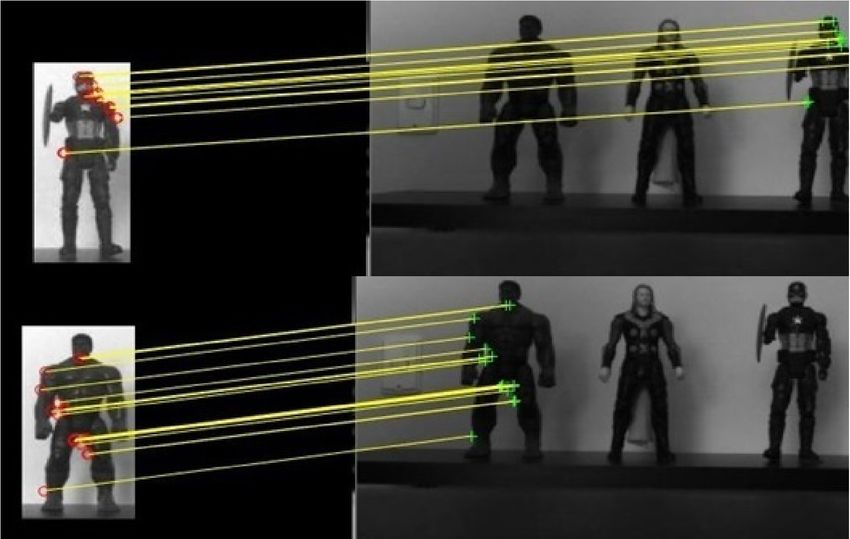
Julian S. Rodriguez. / Electronic Letters on Computer Vision and Image Analysis 20(1):16-27, 2021            17

extrinsic parameters obtained from camera calibration are used to get coordinates in a scene, although depth
information must be estimated; other works use stereo calibration employing two cameras in order to get depth
information [10].

   Recently, depth cameras that use a laser sensor to get information of three dimensions in a scene have been
used, the most popular is Microsoft’s Kinect which has been employed in investigations in several areas in-
cluding face recognition [11], 3D scene reconstruction [12] and human-machine interfaces [13]. Employing
a sensor that combine RGB camera advantages, this means, the possibility of getting information about mor-
phology and characteristics of an object, with a laser sensor to obtain real information of the depth, allows for
determining an object position in the space regarding a coordinate origin without using more than a camera,
that allows for getting a system less expensive in terms of economy and computing. Furthermore, there is an
emerging market of stereo cameras that use information from two lenses to calculate objects volume and depth
employing the epipolar geometry theory [14].
In this paper algorithms of objects recognition in a scene are employed, and the centroid coordinates of the
object in order to be used in the object tracking by a robot are obtained. All the process is carried out using two
cameras separately: (a Kinect and a stereo camera). The results that were obtained are compared to determine
which one is the most suitable to do the previous task according the camera (RGB for Kinect and monochro-
matic for the stereo) and the technique to calculate the depth of them.
This paper is divided by this way: in the section 2 there is a literature review about the most used descriptors of
characteristics to objects recognition, as well as the cameras employed in this work. In the section 3 the used
methodology is described through every phase, in this way, the section number 3.2 explains in detail the object
recognition in the scene and its segmentation phase; in the 3.3 section the camera information (camera matrix)
with the depth information are employed to obtain the real location of a segmented object regarding the image
plane; in the 3.4 section the coordinates of a found point regarding the base of the robot serial are shown; in the
4 section the analysis and discussion of results are presented.

2    State of the art
Several algorithms have been developed in order to find characteristics of interest within images, those charac-
teristics are generally employed to locate connections between images to obtain similarities between them and
to find determinate objects. The most used algorithms are “Scale-invariant feature transform (SIFT” [15],“Cen-
ter surround extremas for realtime feature detection and matching (CenSurE)” [16] , “Difference of Circles
(Doc)” [17] and “Speeded-Up Robust Features (SURF)” [18] and “KAZE”; every one of them has some advan-
tages regarding the amount of similarities that can be found, the time of formulation or invariants in relation to
position or scale and other characteristics. In [19] a comparative analysis of different descriptors is carried out
where KAZE stands out in several aspects.
Alcantarilla et al. [20] presented KAZE characteristics that exploit a nonlinear scale space through a nonlinear
diffusion filtering. That makes the soft focus of images adapt locally to the characteristic points, in this way
noise is reduced and at the same time the limits of images areas are preserved. KAZE detector is based on scale
normalized determinant of Hessian Matrix (Equation 1), which is calculated in several scale levels.

                                                            ∂ 2 f (x)
                                              Hf (X)ij =                                                       (1)
                                                            ∂xi ∂xj
   Response maximum of the detector are collected as characteristic points using a movable window. The de-
scription of characteristic introduces the rotational invariance property when the dominant rotation in a circular
neighborhood around every detected characteristic is found. KAZE characteristics are invariant in relation to
rotation, scale and limited affinity, and they have a better recognizing in variable scales with a moderate in-
crease in computing time.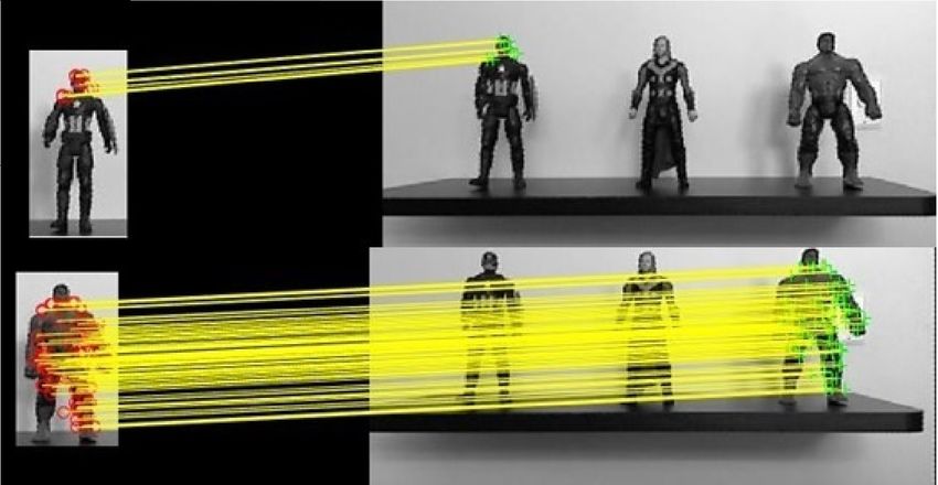
18          Julian S. Rodriguez. / Electronic Letters on Computer Vision and Image Analysis 20(1):16-27, 2021

The second equation (Equation 2) shows the classic nonlinear diffusion formulation.

                                           ∂L
                                                = div(c(x, y)).∇L                                            (2)
                                            ∂t
   Where “c” is a conductivity function, “div” is divergence, ∇is gradient operators and “L” is luminance of
the image.
Furthermore, different devices have recently been developed which allows for an image acquisition as a con-
ventional camera and obtaining depth information, that permits to get information of 3D objects. As it was told
previously, one of the most popular devices is Microsoft’s Kinect that employ an infrared projector, as well as
an infrared camera to produce an image of depth, additionally, Kinect sensor reproduces video with a frequency
of 30 Hz in RGB 32-bit color and a VGA resolution of 640X480 pixels, QVGA resolution of 620X480 pixels.
The limit of Kinect visual range is between 1 and 3.5m of distance with a 57o visual angle horizontally and a
43o angle vertically [21].
Besides Kinect, stereo cameras have been popularized, with them it is possible to get information of depth
through triangulation of the epipolar geometry. Particularly, the camera that was used in this work is an e-Con
System Tara which has two monochromatic cameras with resolutions of 752X480, 640X480 and 320X240 at
60 fps and a distance of base line of 60 mm[22].

3     Method
This paper has two fundamental objectives, the first one is to recognize the position of a specific object in a
scene through a camera in real time in order to determine the spatial location of its mass center in relation to
the coordinate system of a serial robot; the second one is to compare the results of both kinds of camera that
are able to provide 3D information. The Figure 1 shows Phases that are employed to carry out the objective’s
achievement.

                Adequacy of cameras and
                   work environment                        Image capture                       Object recognition
                 Lighting conditions and distance
                                                          • Separate objects              Find similarities between the object
                between camera and object to be
                                                    •   Multiple objects within a scene                and a scene
                          photographed

                                                          Modification of                   Determination of spatial
                                                        coordinates system                        location
                                                    The coordinates of the point of the     The depth information from the
                                                      camera's reference system are        cameras is used to determine the
                                                       transformed to the reference       3D coordinates of the center of the
                                                          system of a robot arm                   recognized object.

                        Figure 1: Block diagram of the methodology used. Source: Author

3.1   Adequacy of cameras and work environment
Both cameras and objects to be photographed are located at 80 cm height, the distance between objects and
camera could be between 0.5m and 1.5m; moreover, there is just one light source to guarantee that photographs
are taken under the same circumstances. Figure 2 shows the described adequacy.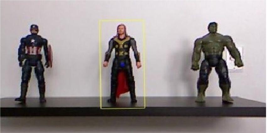
Julian S. Rodriguez. / Electronic Letters on Computer Vision and Image Analysis 20(1):16-27, 2021 19
Figure 2: Conditions that were used to take images. Source: Author
3.2 Object recognition
Regarding object recognition, literature presents experiments that were carried out according databases which
contain 2D and 3D images in several categories, there are some examples in [23] and [24]. In this paper, pic-
tures of objects with similar characteristics are taken and three toy figures were chosen: captain America, Thor
and Hulk. In order to do the recognition, image characteristics of every object are extracted separately to search
similarities in them and the scene that was registered in real time with every camera.
As it was presented previously, it is possible to obtain the characteristics according several techniques, some
of them are Scale-invariant feature transform (SIFT), Center surround extremas for realtime feature detection
and matching (CenSurE), Difference of Circles (Doc) y Speeded-Up Robust Features (SURF), although KAZE
is used in this work because of the comparative analysis that was carried out in [19] showed that KAZE has a
better performance and results in the similarity of characteristics by point.
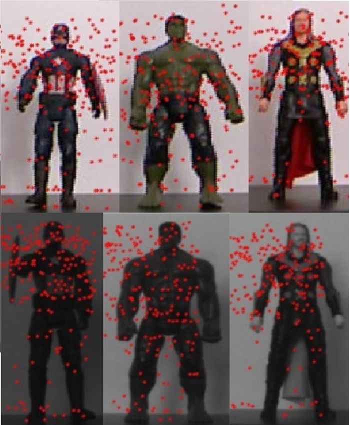
Following the previous phases in relation to KAZE descriptor, characteristic points of interest that were found
separately by the descriptor for each object are presented in figure 3.
The best bin first [25] was the algorithm used to search similarities, that makes the characteristics of the
object coincide with those neighbors of the image which is called scene. The algorithm calculates the distance
between vectors of the characteristics in the objects and in the scene to carry out the similarity; the nearest
neighbor is defined as the main point with a minimum Euclidean distance to the vector descriptor; in figures 4
and 5 similarities found between both objects and scenes are shown
3.3 Determination of spatial location
When the similarities between the characteristics of points of interest in the images of objects and the scene, the
result is the object recognition in the set. Spatial location that is wanted to be found is that one of the centroid
of polygon which surrounds the object in the scene, there is an example in figure 6 where one of the recognized
objects is shown, and also its centroid is highlighted with an asterisk.
Pinhole model describes the geometric relationship between an object coordinates in a 3D space and its pro-
jection in an image plane of a camera [26]. Figure 7 illustrates geometric relationships between a point and its
projection, those are represented in equation 3.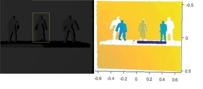
20 Julian S. Rodriguez. / Electronic Letters on Computer Vision and Image Analysis 20(1):16-27, 2021
Figure 3: Points of interest detected by KAZE algorithm for each reference object. Top row taken by a Kinect.
Lower row taken by a stereo camera. Source: Author
Figure 4: Similarity of points for both objects with Kinect. Source: Author
Figure 5: Similarity of points for both objects with stereo camera. Source: Author
Xw
u h i Yw
v =K R T (3)
Zw
1
1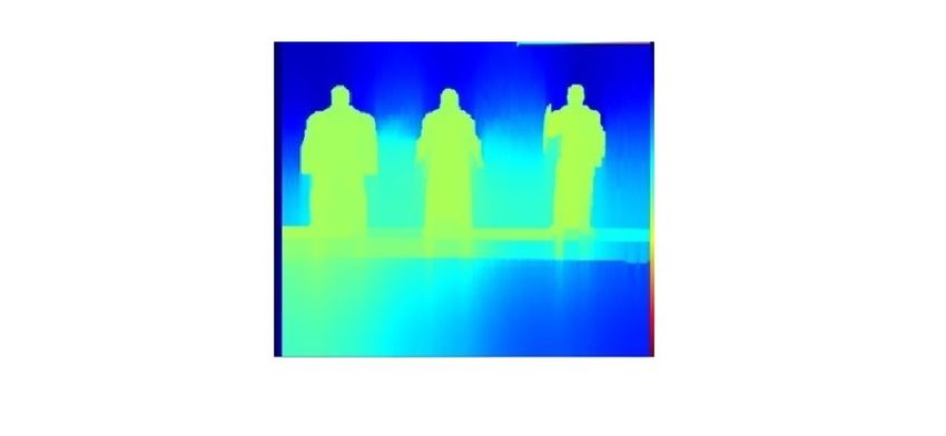
Julian S. Rodriguez. / Electronic Letters on Computer Vision and Image Analysis 20(1):16-27, 2021 21
Figure 6: Recognized object in a scene. Source: Author
Figure 7: Geometric model of camera. [26]
Where [u, v, 1] and [Xw, Y w, Zw] are the homogeneous coordinates of a point in the image and in the 3D
scene respectively; K is the matrix of intrinsic parameters of camera that is composed of the components of
focal distance (f x, f y), coordinates of principal point o0 (u0, v0) and distortion factor (s) which are organized
according the equation 4; R and T are rotation and translation matrix to point the scene toward coordinates of
the camera known as extrinsic parameters.
f x s u0
K = 0 f y v0 (4)
0 0 1
Intrinsic and extrinsic parameters of Kinect camera are found according the calibration procedure described
in [27], where an image that works as a pattern with known conditions (usually a chess board) is employed
to generate relationships of real world (XW , YW , ZW ) in meters with coordinates in the image. K matrix is
important during the calibration procedure, regardless correction factor s, equation 5 is presented.
530.12 0 239.21
K= 0 525.96 266.43 (5)
0 0 1
Despite it is possible to estimate the position without having an exact measure of depth, in order to get a
later application of positioning, unwanted paths can be generated [28]. For that reason, depth data provided
by the selected cameras is employed in this work. Operating range of Kinect is between 1m and 3.5m while
stereo camera’s goes from 0.5m to 3m, that limits the possibility of getting a complete spatial information from
images which were acquired in those ranges.
Figure 8 shows the depth map generated by Kinect for the scene where one of the objects of search is recog-
nized, as well as a 3D point cloud that is represented in the scene; depth data is taken in the coordinates of
polygon centroid that surrounds the known object, in that way with an application of equation 3 it is possible
to obtain information about real coordinates of that point location.
Similarly, figure 9 shows the disparity map obtained with stereo camera that allows for getting depth data.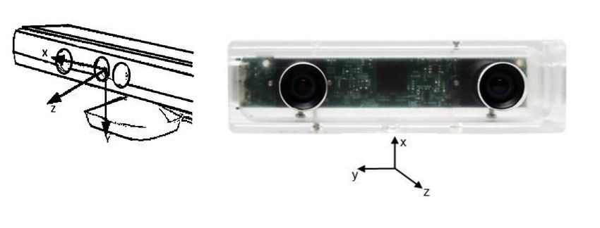
22          Julian S. Rodriguez. / Electronic Letters on Computer Vision and Image Analysis 20(1):16-27, 2021

Figure 8: Map of depth of the scene with recognized object. And point cloud obtained with Kinect. Source:
Author

                    Figure 9: Disparity map obtained with stereo camera. Source: Author

3.4   Modification of coordinates system

Both location of the base of a classifier arm and camera location are fixed. In that way, a transformation based
in the rotation matrix and the translation vector between systems of coordinates is employed in order to convert
the object location of coordinates of the camera into a reference system placed at the base of robot [29]. That
converts the point of the camera which was found (shown in the system (Xc, Y c, Zc)) into one that has as
reference the system (XR, Y R, ZR) corresponding to the robot. (10)

                    Figure 10: Coordinates systems of camera and robot. Source: Author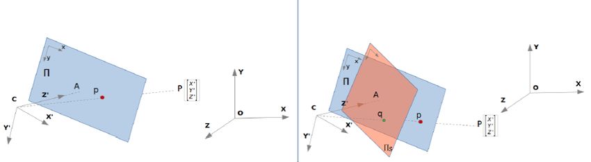
Julian S. Rodriguez. / Electronic Letters on Computer Vision and Image Analysis 20(1):16-27, 2021         23

4     RESULTS AND DISCUSSION

As it was mentioned previously, this paper objectives are comparing the achievement of both cameras in objects
recognition and spatial position. Thus, an experiment was made to valid each objective. The procedure and
results are discussed below:

4.1   Objects recognition

Images of the same scene form different distances varying objects location and amount were taken. The proce-
dure explained in methodology was applied for each image by calculating characteristic points through KAZE
detector in order to find coincidences in the images. Since 1,5m, images that were taken with any camera
have percentages of recognition too low, hence it is not appropriate to recognize objects. That is why distances
are modified until 1,5m. Table 1 sums up the percentages of recognition obtained according the distance of
acquisition of Kinect, and in Table 2, there are the same results but with a stereo camera.

                Table 1: Results of object recognition in the scene with Kinect. Source: Author
                             Distance/Object Captain America Hulk Thor
                                   0,50 m               95%           97% 90%
                                    0,7 m               90%           80% 75%
                                    0,8m                90%           80% 75%
                                     1m                 86%           75% 70%
                                    1,2m                80%           70% 55%
                                    1,5 m               75%           50% 45%

            Table 2: Results of object recognition in the scene with stereo camera. Source: Author
                              Distance/Object Captain America Hulk Thor
                                  0,50 m                95%           97% 90%
                                   0,7 m                90%           80% 75%
                                   0,8m                 90%           80% 75%
                                    1m                  80%           75% 70%
                                   1,2m                 75%           62% 50%
                                   1,5 m                40%           35% 35%

   Two main aspects are shown in tables 1 and 2. First, the results of recognition of images that were obtained
by the stereo camera are slightly fewer than those obtained by Kinect, which can be attributed to the fact that
the images of a stereo camera are slightly darker than those of Kinect, despite photographs are taken with the
same resolution and under the same conditions of illumination. Moreover, the percentage of recognition of
objects decreases when distance increases with both cameras, that is due to image resolution is low.

   After knowing the results of Tables, it is found that images of the scene must be taken at a 0.5m distance
in order to obtain better results; although, according the objective of this work, that could not be possible with
Kinect due to the range of infrared operation starts at 0.8m, it means, the object would be recognized with a
shorter distance, but it is not possible to find real information of depth.
24 Julian S. Rodriguez. / Electronic Letters on Computer Vision and Image Analysis 20(1):16-27, 2021
Figure 11: Coordinates systems of Kinect and stereo camera Tara. [22]
4.2 Validation of objects location
New images with both devices are taken to valid coordinates that are known and related to the sensor. Centroid
coordinates of each object are obtained according to the procedure presented in section 3, and the results are
obtained according to the coordinate system presented in Figure 10. Each distance from sensor to the center
of the object is validate by measuring centroid location of the object using a measuring tape in order to verify
the algorithm results. Results are summed up in Figures 12 and 13 where the vertical axis represents the given
measure using a specific camera, and the horizonal axis concerns to the measure found with the measuring tape.
180
160
Kinect Measure
140
120
100 Captain America
Thor
Hulk
80
80 100 120 140 160 180
Actual Measure(cm)
Figure 12: Measures taken with Kinect Vs Distances measured physically. Source: Author
180
Measurement With Stereo Camera
160
140
120
100 Captain America
Thor
Hulk
80
80 100 120 140 160 180
Actual Measure(cm)
Figure 13: Measures taken with stereo camera Vs Distances measured physically. Source: AuthorJulian S. Rodriguez. / Electronic Letters on Computer Vision and Image Analysis 20(1):16-27, 2021 25
Despite differences between the measures of distances of each object with both cameras, the results pre-
sented in Figures 12 and 13 show the high precision of the distances data taken with Kinect sensor and the
stereo camera, at less for the objective of this work. However, it is possible to deduce that applications where a
bigger level of precision as an assembly of little pieces is required, probably a determination of the real location
of a robot could not happen due to the differences between the order of millimeters. Moreover, Table 3 allows
to have a better depiction of the differences between both devices with a summary of the percentage faults on
average of objects distances taken by each camera.
Table 3: Average percentage errors in the distances of each object. Source: Author
Object/Camera Kinect Stereo
Captain America 1.2% 2.18%
Thor 1.36% 1.88%
Hulk 1.75% 3.19%
General Average 1.44% 2.42%
This Table shows Kinect sensor has less faults with distances measures related to the stereo camera for each
object.
After making the experiments presented and noticing there are some differences between the measures of
distance for each object with both devices, a third experiment is made without any predetermined object, but
by measuring distances to a flat object in order to verify the difference in the result with any dependence on a
specific figure. Again, the distances that were obtained are valid with a measuring tape. Figure 14 shows the
given results and Table 4 represents the percentage faults on average of the distance from each camera to a flat
object.
180
160
Measure on flat pattern
140
120
100
Kinect
Cámara Estéreo
80
80 100 120 140 160 180
Actual Measure(cm)
Figure 14: Measures of distance taken on a flat pattern with stereo camera Vs Kinect. Source: Author
Table 4: Average percentage errors of the distance measurement of each camera to a flat object. Source: Author
Object/Camera Kinect Stereo
Average error percentage 0.82% 2.61%
The response of measures taken on a flat pattern is generally more lineal in relation to measures on other
objects for Kinect, that allows for deducing the response in sensor depth depends on reflection surface due to
the material or shape. Furthermore, measures taken with the stereo camera are slightly on the real ones, that
means Kinect has a better precision with the distance measure regardless the objective of this work.26 Julian S. Rodriguez. / Electronic Letters on Computer Vision and Image Analysis 20(1):16-27, 2021
5 Conclusion
Depth data was employed, as well as the information of image provided by a RGB-D camera (Kinect), and a
stereo camera using calibration parameters to determine the real position of the center of an object in a scene,
experiments of recognition of objects with similar characteristics in the scene were done applying KAZE algo-
rithm; moreover, the results of depth that was obtained in relation to camera shot were verified.
Images must be taken in short distances (less than 0.5m) to obtain satisfactory results in relation to object
recognition due to the low resolution of cameras that were employed. According to those conditions Kinect
proved it has a better achievement in the recognition task with characteristic points developed by KAZE algo-
rithm.
Regarding depth data provided by cameras is the right one to achieve the objective of this work, although, the
operation ranges of Kinect (1m - 2.5m) and stereo camera (0.5m - 3m) do not allow the object to be recognized
in the scene in several times despite depth data that was provided by cameras is satisfactory.
Kinect proved a better achievement in the precision of distance measure once again, with an average general
fault of 1.44% instead of 2.42% given by the stereo camera for the measure of the centroid of predetermined
objects, and 0.82% instead of 2.62% in the distance to a pattern of flat surface.
Validations of distances show it is possible to obtain coordinates and depth data in order to achieve the
wanted application. Although, there is a variation in relation to the distance and the object according the same
distances taken in a flat pattern, for that reason, formal research on precision of depth data for Kinect according
the reflection surface and other variables carried out in a future work could be something interesting.
References
[1] Wanbing Zhao et al. “Robust Visual Servoing Control for Ground Target Tracking of Quadrotors”. In:
IEEE Transactions on Control Systems Technology (2019). DOI: 10.1109/TCST.2019.2922159.
[2] Xu Jin. “Iterative learning control for non-repetitive trajectory tracking of robot manipulators with joint
position constraints and actuator faults”. In: International Journal of Adaptive Control and Signal Pro-
cessing 31.6 (2017), pp. 859–875. DOI: 10.1002/acs.1098.
[3] Jinquan Li et al. “Structured Light-Based Visual Servoing for Robotic Pipe Welding Pose Optimization”.
In: IEEE Access 7 (2019), pp. 138327–138340. DOI: 10.1109/ACCESS.2019.2943248.
[4] Chicheng Liu et al. “Non-vector space visual servoing for multiple pin-in-hole assembly by robot”. In:
2016 IEEE Workshop on Advanced Robotics and its Social Impacts (ARSO). IEEE. 2016, pp. 134–140.
DOI : 10.1109/ARSO.2016.7736270.
[5] Lesley-Ann Duflot et al. “Shearlet-based vs. photometric-based visual servoing for robot-assisted medi-
cal applications”. In: 2016 IEEE/RSJ International Conference on Intelligent Robots and Systems (IROS).
IEEE. 2016, pp. 4099–4104. DOI: 10.1109/IROS.2016.7759603.
[6] Joonho Seo et al. “Ultrasound image based visual servoing for moving target ablation by high intensity
focused ultrasound”. In: The International Journal of Medical Robotics and Computer Assisted Surgery
13.4 (2017), e1793. DOI: https://doi.org/10.1002/rcs.1793.
[7] Mien Van et al. “Fault diagnosis in image-based visual servoing with eye-in-hand configurations using
kalman filter”. In: IEEE Transactions on Industrial Informatics 12.6 (2016), pp. 1998–2007. DOI: 10.
1109/TII.2016.2590338.Julian S. Rodriguez. / Electronic Letters on Computer Vision and Image Analysis 20(1):16-27, 2021 27
[8] Hao Xu, Hesheng Wang, and Weidong Chen. “Uncalibrated visual servoing of mobile manipulators
with an eye-to-hand camera”. In: 2016 IEEE International Conference on Robotics and Biomimetics
(ROBIO). IEEE. 2016, pp. 2145–2150. DOI: 10.1109/ROBIO.2016.7866647.
[9] Josue Lopez-Leyva et al. “Automatic visual servoing control system for industrial robots in arbitrary
work areas based on M-PBVS technique”. In: Acta Technica Napocensis-Series: Applied Mathematics,
Mechanics, and Engineering 62.3 (2019).
[10] Georg R Mueller and Hans-Joachim Wuensche. “Continuous extrinsic online calibration for stereo cam-
eras”. In: 2016 IEEE Intelligent Vehicles Symposium (IV). IEEE. 2016, pp. 966–971. DOI: 10.1109/
IVS.2016.7535505.
[11] Billy YL Li et al. “Using kinect for face recognition under varying poses, expressions, illumination and
disguise”. In: 2013 IEEE workshop on applications of computer vision (WACV). IEEE. 2013, pp. 186–
192. DOI: 10.1109/WACV.2013.6475017.
[12] Ming-Der Yang et al. “Image-based 3D scene reconstruction and exploration in augmented reality”.
In: Automation in Construction 33 (2013), pp. 48–60. DOI: https : / / doi . org / 10 . 1016 / j .
autcon.2012.09.017.
[13] Vinayak Kamath and Sandeep Bhat. “Kinect sensor based real-time robot path planning using hand ges-
ture and clap sound”. In: International Conference on Circuits, Communication, Control and Computing.
IEEE. 2014, pp. 129–134. DOI: 10.1109/CIMCA.2014.7057774.
[14] Gang Xu and Zhengyou Zhang. Epipolar geometry in stereo, motion and object recognition: a unified
approach. Vol. 6. Springer Science & Business Media, 2013.
[15] DG Lown. “Distinctive Image Features form Scale-Invariant Keypoint”. In: Int’l Journal of Computer
Vision 60.2 (2014). DOI: https://doi.org/10.1023/B:VISI.0000029664.99615.94.
[16] Agrawal Motilal and Konoligeand MortenRufusBlas Kurt. “CenSurE: Center Surround Extremas for Re-
altime Feature Detection and Matching”. In: Computer Vision - ECCV 2008, 10th European Conference
on Computer Vision. Computer Vision - ECCV 2008. 2008, pp. 102–115. DOI: https://doi.org/
10.1007/978-3-540-88693-8_8.
[17] A. Hojaij et al. “Difference of Circles Feature Detector”. In: 2012 Ninth Conference on Computer and
Robot Vision. 2012, pp. 63–69. DOI: 10.1109/CRV.2012.16.
[18] Herbert Bay et al. “Speeded-Up Robust Features (SURF)”. In: Computer Vision and Image Under-
standing 110.3 (2008). Similarity Matching in Computer Vision and Multimedia, pp. 346–359. ISSN:
1077-3142. DOI: https : / / doi . org / 10 . 1016 / j . cviu . 2007 . 09 . 014. URL: http :
//www.sciencedirect.com/science/article/pii/S1077314207001555.
[19] Shaharyar Ahmed Khan Tareen and Zahra Saleem. “A comparative analysis of sift, surf, kaze, akaze, orb,
and brisk”. In: 2018 International conference on computing, mathematics and engineering technologies
(iCoMET). IEEE. 2018, pp. 1–10. DOI: 10.1109/ICOMET.2018.8346440.
[20] Pablo Fernández Alcantarilla, Adrien Bartoli, and Andrew J. Davison. “KAZE Features”. In: Computer
Vision – ECCV 2012. Ed. by Andrew Fitzgibbon et al. Berlin, Heidelberg: Springer Berlin Heidelberg,
2012, pp. 214–227. ISBN: 978-3-642-33783-3.
[21] Zhengyou Zhang. “Microsoft Kinect Sensor and Its Effect”. In: IEEE MultiMedia 19 (Apr. 2012), pp. 4–
12. DOI: 10 . 1109 / MMUL . 2012 . 24. URL: https : / / www . microsoft . com / en - us /
research/publication/microsoft-kinect-sensor-and-its-effect/.
[22] e-con Systems India Pvt Ltd. MU Sample Application User. 2014.
[23] Alina Kuznetsova et al. “The open images dataset v4: Unified image classification, object detection, and
visual relationship detection at scale”. In: arXiv preprint arXiv:1811.00982 (2018). DOI: 10.1007/
s11263-020-01316-z.28 Julian S. Rodriguez. / Electronic Letters on Computer Vision and Image Analysis 20(1):16-27, 2021
[24] Mona Jalal et al. “Sidod: A synthetic image dataset for 3d object pose recognition with distractors”. In:
Proceedings of the IEEE Conference on Computer Vision and Pattern Recognition Workshops. 2019,
pp. 475–477.
[25] Zhenjie Chen and Jingqi Yan. “Fast KNN search for big data with set compression tree and best bin
first”. In: 2016 2nd International Conference on Cloud Computing and Internet of Things (CCIOT).
IEEE. 2016, pp. 97–100. DOI: 10.1109/CCIOT.2016.7868311.
[26] Philippe Cornic et al. “Another look at volume self-calibration: calibration and self-calibration within a
pinhole model of Scheimpflug cameras”. In: Measurement Science and Technology 27.9 (2016), p. 094004.
[27] Xiaowei Hu et al. “A robust and accurate calibration method for out-of-focus camera”. In: Electronic
Imaging 2018.2 (2018), pp. 263–1. DOI: https://doi.org/10.2352/ISSN.2470- 1173.
2018.2.VIPC-263.
[28] Gabriel J Garcia et al. “Guidance of robot arms using depth data from RGB-D camera”. In: 10th Inter-
national Conference on Informatics in Control, Automation and Robotics (ICINCO 2013). 2013. DOI:
10.5220/0004481903150321.
[29] Bruno Siciliano et al. Robotics. 1st ed. Springer-Verlag London, 2009. ISBN: 978-1-84996-634-4. DOI:
10.1007/978-1-84628-642-1.You can also read