A technical-economic analysis of turbine inlet air cooling for a heavy duty gas turbine operating with blast-furnace gas
←
→
Page content transcription
If your browser does not render page correctly, please read the page content below
Research, Society and Development, v. 10, n. 9, e59810915006, 2021
 (CC BY 4.0) | ISSN 2525-3409 | DOI: http://dx.doi.org/10.33448/rsd-v10i9.15006

A technical-economic analysis of turbine inlet air cooling for a heavy duty gas
turbine operating with blast-furnace gas
Análise técnico-econômica do resfriamento do ar de entrada do compressor de uma turbina a gás
heavy duty operando com gás de alto-forno
Análisis técnico-económico de la refrigeración del aire de entrada de la turbina para una turbina
de gas de gran potencia que funciona con gas de alto horno

 Received: 04/13/2021 | Reviewed: 04/20/2021 | Accept: 07/28/2021 | Published: 07/29/2021

 Raphael Camargo da Costa
 ORCID: https://orcid.org/0000-0001-5220-4652
 WayCarbon, Sustentabilidade, Brazil
 E-mail: raphael.camargo@waycarbon.com
 Cesar Augusto Arezo e Silva Jr.
 ORCID: https://orcid.org/0000-0002-9842-6522
 Energy Control Center - ECC, Thermo Electric Power Plant, Brazil
 E-mail: cesar.arezo@hotmail.com
 Júlio Cesar Costa Campos
 ORCID: https://orcid.org/0000-0002-9488-8164
 Federal University of São João Del Rei, Brazil
 c
 Federal University of Viçosa, Brazil
 E-mail: julio.campos@ufv.br
 Washington Orlando Irrazabal Bohorquez
 ORCID: https://orcid.org/0000-0002-9762-0665
 Federal University of Juiz de Fora, Brazil
 E-mail: washington.irrazabal@ufjf.edu.br
 Rogério Fernandes Brito
 ORCID: https://orcid.org/0000-0002-6833-7801
 Federal University of Itajubá, Brazil
 E-mail rogbrito@unifei.edu.br
 Antônio M. Siqueira
 ORCID: https://orcid.org/0000-0001-9334-0394
 Federal University of Viçosa, Brazil
 E-mail: antonio.siqueira@ufv.br

 Abstract
 The study was developed inside an integrated steel mill, located in Rio de Janeiro city, aiming to analyse the technical-
 economic feasibility of installing a new inlet air refrigeration system for the gas turbines. The technologies applied for
 such purpose are named Turbine Inlet Air Cooling (TIAC) technologies. The power plant utilizes High Fogging and
 Evaporative Cooling methods for reducing the compressor’s inlet air temperature, however, the ambient climate
 condition hampers the turbine’s power output when considering its design operation values. Hence, this study was
 proposed to analyse the installation of an additional cooling system. The abovementioned power plant has two heavy-
 duty gas turbines and one steam turbine, connected in a combined cycle configuration. The cycle nominal power
 generation capacity is 450 MW with each of the gas turbines responsible for 90 MW. The gas turbines operate with
 steelwork gases, mainly blast furnace gas (BFG), and natural gas. The plant has its own weather station, which provided
 significant and precise data regarding the local climate conditions over the year of 2017. An in-house computer model
 was created to simulate the gas turbine power generation and fuel consumption considering both cases: with the
 proposed TIAC system and without it, allowing the evaluation of the power output increase due to the new refrigeration
 system. The results point out for improvements of 4.22% on the power output, corresponding to the electricity demand
 of approximately 32960 Brazilian homes per month or yearly earnings of 3.92 million USD.
 Keywords: Gas turbine; Blast furnace gas (BFG); Electricity generation; Combined cycle; Steelworks; Turbine Inlet
 Air Cooling (TIAC).
 Resumo
 O estudo foi desenvolvido em uma usina siderúrgica integrada, localizada no Rio de Janeiro, com objetivo de analisar
 a viabilidade técnico-econômica da instalação de um novo sistema de resfriamento do ar de entrada do compressor de
 suas turbinas a gás. As técnicas de resfriamento do ar dos compressores são denominadas Turbine Inlet Air Cooling –
 TIAC. A termelétrica em questão utiliza métodos de nebulização e evaporativos para a redução de temperatura do ar de
 entrada deste compressor, porém as condições climáticas locais impossibilitam a obtenção de valores de geração
 próximos ao do projeto da planta. Por isso, é proposto o referido estudo técnico-econômico da instalação de um sistema
 1
Research, Society and Development, v. 10, n. 9, e59810915006, 2021
 (CC BY 4.0) | ISSN 2525-3409 | DOI: http://dx.doi.org/10.33448/rsd-v10i9.15006

 adicional para resfriamento do ar captado. A planta analisada possui duas turbinas a gás do tipo Heavy Duty operando
 em ciclo combinado e capacidade nominal de 450 MW. As turbinas a gás em questão possuem potência nominal de 90
 MW e opera a partir da combustão de gases de processo siderúrgico, principalmente o gás de alto-forno (BFG). A planta
 possui uma estação meteorológica que forneceu dados para o estudo da eficiência da troca de calor em função das
 condições ambientais. Foram consideradas as condições climáticas, de hora em hora, de todo ano de 2017. Desenvolveu-
 se um modelo computadorizado “in-house” para simular a geração de energia e o consumo de combustível de uma
 turbina com TIAC e sem TIAC, permitindo mensurar o ganho de geração em função do emprego do sistema de
 resfriamento. Os resultados obtidos apontam para um potencial de aumento de potência líquida na turbina a gás de
 4,22%, correspondendo à demanda de eletricidade de aproximadamente 32960 residências brasileiras e receita esperada
 de até 15 milhões de Reais (R$) anuais.
 Palavras-chave: Turbina a gás; Ciclo combinado; Condicionamento de ar; Gás de Alto-Forno (BFG); Modelagem
 de energia; Siderurgia.
 Resumen
 El estudio fue desarrollado dentro de una planta siderúrgica integrada, ubicada en la ciudad de Río de Janeiro, con el
 objetivo de analizar la viabilidad técnico-económica de la instalación de un nuevo sistema de refrigeración por aire de
 entrada para las turbinas de gas. Las tecnologías aplicadas para tal fin se denominan tecnologías TIAC (Turbine Inlet
 Air Cooling). La planta de energía utiliza métodos de alta nebulización y enfriamiento evaporativo para reducir la
 temperatura del aire de entrada del compresor, sin embargo, las condiciones climáticas ambientales dificultan la potencia
 de salida de la turbina cuando se consideran los valores de operación del diseño. Por lo tanto, este estudio fue propuesto
 para analizar la instalación de un sistema de refrigeración adicional. La citada central dispone de dos turbinas de gas de
 gran potencia y una de vapor, conectadas en ciclo combinado. La capacidad nominal de generación de energía del ciclo
 es de 450 MW con cada una de las turbinas de gas responsables de 90 MW. Las turbinas de gas funcionan con gases de
 trabajo del acero, principalmente gas de alto horno (BFG) y gas natural. La planta tiene su propia estación
 meteorológica, que proporciona datos significativos y precisos sobre las condiciones climáticas locales durante el año
 2017. Se creó un modelo informático interno para simular la generación de energía de la turbina de gas y el consumo
 de combustible considerando ambos casos: con el sistema TIAC propuesto y sin él, permitiendo evaluar el aumento de
 potencia debido al nuevo sistema de refrigeración. Los resultados apuntan a mejoras del 4,22% en la producción de
 energía, correspondientes a la demanda de electricidad de aproximadamente 3.2960 hogares brasileños por mes o
 ganancias anuales de 3,92 millones de dólares.
 Palabras clave: Turbina de gas; Gas de Alto Horno (BFG); Modelado energético; Ciclo combinado; Siderúrgica;
 Enfriamiento de Aire de Entrada a la Turbina (TIAC).

Nomenclature

 Upper Case Lower Case
 Air − Fuel Ratio Heat Capacity
 Annual Gain Mass
 Composite Annual Gain Subscripts
 Coefficient of Performance Air
 Latent Heat Atmospheric
 Molar Mass Average
 Pressure Blast Furnace Gas
 Power Output Air Compressor
 Heat BFG Compressor
 Temperature With Cooling
 Temperature After Turbine Dry Bulb
 Turbine Inlet Temperature Exhaust Gas
 Work Inlet
 Greek Latent
 Heat Capacity Ratio Sensible
 Specific Volume Saturation
 Relative Humidity Turbine
 Specific Humidity Water Vapour
 Efficiency Wet Air
 Water
 Without Cooling

 2
Research, Society and Development, v. 10, n. 9, e59810915006, 2021
 (CC BY 4.0) | ISSN 2525-3409 | DOI: http://dx.doi.org/10.33448/rsd-v10i9.15006

Highlights

Major contributions:

 • Explanation of versatile methodology, adopted by a modern power plant, used to evaluate economically the gas
 turbines’ output gains due to turbine inlet air cooling;
 • The first study of its kind developed for turbines operating on blast furnace gas and in tropical humid conditions.

 Minor contributions:

 • Contextualization of a thermo electrical power plant operating on combined cycle configuration and installed
 inside an integrated steel mill;
 • Real case application of the First Law of Thermodynamics.

1. Introduction
 Nowadays, the modern society requirement for energy is continuously raising and studies indicate an annual average
growth rate of approximately 6% on the global electricity demand (Ibrahim, et al., 2018). Following the environmental concerns
regarding climate change, the need for optimization on energy generation processes is verified (Ersayin & Ozgener, 2015),
(Chowdhury, et al., 2018). In this context, a way to utilize energetic resources more efficiently is to produce electricity via
combined cycle power plants (Poullikkas, 2005).
 In a simple manner, the principle for electricity generation on a combined cycle power plant is based on the high
temperatures of the gas turbine (GT) exhaust gases, which are directed to a Heat Recovery Steam Generator (HRSG) providing
enough energy for the steam to move a steam turbine. In other words: the gas turbine Brayton cycle (bottom cycle) is connected
to the steam turbine Rankine cycle (top cycle) through a HRSG, hence the combined cycle terminology (Jeffs, 2008).
 The combined cycle configuration can be designed to operate integrated with an industrial process that involves the
formation of gases and water vapour, such configuration is utilized in industries worldwide to enhance the efficiency of
powertrains, optimizing the energy generation process and reducing its inherent costs and environmental consequences (Ersayin
& Ozgener, 2015), (Jeffs, 2008).
 The electricity demand for the integrated steel mill where this study was conducted is met through the operation of a
combined cycle power plant that uses steelwork gases, mainly blast furnace gas (BFG), as fuel for the gas turbines. The usage
of steelwork gases as fuel is widespread in similar industries, as the steelmaking process itself is energy-intensive and generates
plenty of such gases in the fabrication of pig iron and steel (Uribe-Soto, et al., 2017). Improvements in energy and resources
efficiency are a priority for such industries, especially in times of raising competitiveness, environmental concerns and volatility
in electricity prices (He & Wang, 2017).
 Therefore, researches involving performance enhancement, economics and environment in the context of energy
generation are extremely important in a world of raising awareness concerning sustainable development.
 Modesto and Nebra (2009) and Yao, et al., (2013) present exergo-economic analyses of power generation systems
utilizing steelwork gases, Ibrahim, et al., (2018) perform a review about the exergetic analysis in combined cycle power plants.
Temir and Bilge (2004) discuss a thermoeconomical analysis of a trigeneration system, considering operation and installation
costs and suggesting changes in the parameters of operation for efficiency improvement. Shirazi, et al., (2014) provide a thermo-
economic-environmental analysis for a TIAC system and Ersayin and Ozgener (2015) analyse the performance of a combined
cycle power plant through the first and second law of thermodynamics.
 The majority of the thermoelectric power plants installed in steel plants operate only in the Rankine cycle. Ryzhkov, et
al., (2016) present 42 thermoelectric power plants operating in combined cycle and utilizing BFG or a mix of steelwork gases as

 3
Research, Society and Development, v. 10, n. 9, e59810915006, 2021
 (CC BY 4.0) | ISSN 2525-3409 | DOI: http://dx.doi.org/10.33448/rsd-v10i9.15006

fuel for the gas turbines. However, the power plant analysed in this study is the first of its kind located in the Southern hemisphere
and in tropical humid climate conditions. The studied power plant is located in Rio the Janeiro city, Brazil.
 The ambient air temperature holds influence in a gas turbine capacity of generating energy (Shi, et al., 2010). For an
increase in ambient air temperature from 15°C to 35°C the power output can be reduced from 14% to 20% (Mustapha, 2007). It
is important to emphasize that gas turbines are designed to operate in specific conditions. For the turbine’s compressor inlet air
temperature the ISO Standard, with a temperature of 15°C, is considered (Poullikkas, 2005), (Kakaras, et al., 2004).
 Nevertheless, when considering practical situations, gas turbines may function in ambient conditions that are distant
from the designed point, as the ones installed in intertropical countries with higher average temperatures and relative humidity
(RH). Such conditions undermine turbine performance during a considerable amount of its operating time.
 In that sense, turbine inlet air cooling (TIAC) technologies are applied to bring the ambient air temperature to values
closer to the designed ISO standards.
 The positive impact of applying TIAC technologies is evidenced by Kakaras, et al., (2004), Alhazmy and Najjar, (2004),
Ibrahim, et al., (2011) and Noroozian and Bidi, (2016). For inlet temperatures ranging from 12°C to 15°C considerable power
output gains are achieved. Kamal, et al., (2017) point out a 3,9% power output improvement on a natural gas turbine operating
in the Malaysian climate, due to the installation of an electric chiller.
 The studied thermoelectric power plant utilizes Evaporative Cooling (EC) and High Fogging methods for conditioning
the turbine inlet air. For high temperatures and high relative humidity, the efficiency of evaporative coolers is controversial.
Kamal, et al., (2017) and Santos and Andrade, (2012) point out to the reduced efficiency of EC methods in this context,
meanwhile, Chaker and Meher-Homji, (2007) declare that power output gains ranging from 2% to 5% are possible. What was
observed in the studied power plant corroborates the affirmations of Omar Kamal, et al., (2017) and Santos and Andrade, (2012).
 At the analysed situation, it was possible to measure the air temperature before and after the evaporative cooler through
previously installed sensors and no significant reduction was observed. The ambient air conditions at the power plant site strongly
hamper the efficiency of the EC. For this case study, references uniting TIAC technologies applied in high temperature and high
relative humidity ambient conditions with turbines operating on blast furnace gas were searched but none was found.
 Thereafter, this study was developed to perform a technical-economic analysis and evaluate the feasibility of installing
a new cooling system for the plant’s gas turbines. The adopted premise is the inlet air cooled down to 15°C. The First Law of
Thermodynamics is applied, along with project design data and monitored process’ values to simulate the energy transformation
across the studied gas turbines. Information provided by the plant’s own weather station is also used to define the most relevant
climatic conditions to be simulated and create a model to evaluate the turbines’ operation over the period of one year.

1.1 Turbine inlet air cooling (TIAC) technologies
 The power output gains arising from the application of TIAC technologies are based on simple physical and chemical
principles, but they must be carefully analysed. The Air-Fuel Ratio (AFR) inside a GT combustion chamber is an important
factor to be considered when analysing its power output. The turbine’s compressor admissible air mass flow is proportional to
the ambient air density, this happens because the compressor is a constant volume machine.
 The combustion chamber is also a constant volume machine and, for the combustion process with a fixed AFR, by
cooling the inlet air and increasing the air mass flow, the fuel injection is consequently increased, causing the combustion process
to release more energy (Alhazmy & Najjar, 2004).
 Fuel availability and the economic and environmental impacts of increasing its consumption must also be analysed. For
the studied integrated steel mill, BFG is widely available and very cheap, as it is a by-product of the industry’s main activity.
Using more of it also reduces the need for gas flaring - which is burning the excess gas to relieve reservoir pressure.
 4
Research, Society and Development, v. 10, n. 9, e59810915006, 2021
 (CC BY 4.0) | ISSN 2525-3409 | DOI: http://dx.doi.org/10.33448/rsd-v10i9.15006

1.1.1 Evaporative cooler (EC)
 In the gas turbine context, the Evaporative Cooler is installed at the compressor air inlet. It is a device responsible for
cooling the ambient air through heat exchange with water. The cooling pads behave as wet sponges, where part of the ambient
air heat is transferred to water as latent heat, hence cooling the inlet air (Ibrahim, et al., 2011).

 Figure 1. Evaporative cooler schematics.

 Source: Authors.

1.1.2 Absorption chiller
 Absorption Chillers, as many other types of chillers, are able to condition the ambient air to specific desired
temperatures. Therefore, those devices break the link between the GT power output and the local ambient air conditions, enabling
the generation to remain constant (Kakaras, et al., 2004). For the development of this study, the YORK® YPC Absorption Chiller
with a Coefficient of Performance (COP) of 1.19 was utilized.
 For a chiller equipment, the COP presents the ratio between the thermal energy removed from the environment and the
electric energy provided to achieve the desired temperature, as follows:

 = (1)

1.1.3 Cooling load
 The Cooling Load (CL) is the amount of energy needed to cool the ambient air to the desired temperature. This load
depends on the environmental conditions such as temperature, relative humidity (RH) and atmospheric pressure. The calculations
for the sensible and latent parcels of the CL were made according to Shukla & Singh, (2016), as follows:

 ̇
 ,
 ̇ = , ( , − , ) (2)

 ̇
 ,
 ̇ = [ , ( , , + ) − , ( , , + ) − ( , − , ) , , ] (3)

 = (0.287 + 0.462 , ) (4)

 , = (5)
 ( − )

 5
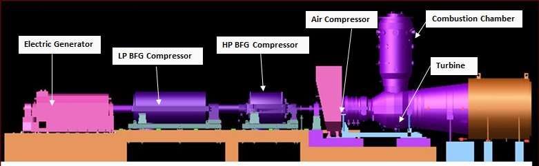
Research, Society and Development, v. 10, n. 9, e59810915006, 2021
 (CC BY 4.0) | ISSN 2525-3409 | DOI: http://dx.doi.org/10.33448/rsd-v10i9.15006

 Thus, it is observable that exists an energetic cost to cool the ambient air. Then, it becomes important to analyse if the
power output gains obtained by TIAC technologies are superior to the amount of energy required to reduce the ambient air
temperature.

1.2 Plant overview
 At the studied power plant, the gas turbines are driven by the combustion of steelwork gases, mainly BFG. Once the
turbines are working, their exhaust gases are each directed to their corresponding HRSG, providing - together with the coke plant
- high-pressure steam for the steam turbine (ST). The power plant installed capacity is 450 MW.
 The electricity generated at the plant exceeds the amount needed for the all the industrial and managerial activities performed
at the site. The surplus is transferred to the national interconnected system, providing electricity for approximately 1 million
residences or 23% of Rio de Janeiro’s state population. Figure 2 shows a representative diagram of the installed combined cycle
configuration for one gas turbine

 Figure 2. Studied power plant combined cycle configuration representation for one gas turbine.

 Source: Authors.

 The studied GTs are ALSTOM GT11N2 60 Hz gas turbines, with power output capacity of 90 MW and are able to
operate with BFG and/or natural gas. They possess, connected to their shafts, three distinct compressors: two for the BFG - one
for low-pressure gas (LP) and the other one for high-pressure gas (HP) - and the other one for ambient air. The powertrain is
represented on Figure 3.

 6
Research, Society and Development, v. 10, n. 9, e59810915006, 2021
 (CC BY 4.0) | ISSN 2525-3409 | DOI: http://dx.doi.org/10.33448/rsd-v10i9.15006

 Figure 3: Powertrain representation.

 Source: Authors.

 BFG is a by-product of the transformation of iron ore in pig iron. It is composed by N 2, CO2, H2, CO and CH4. Pugh, et
al., (2013), Komori, et al., (2003) and Green, et al., (1996) present similar values for its volumetric composition. Table 1 shows
BFG volumetric composition according to Green, et al., (1996).
 Detailed information on steel making and BFG formation can be found in Pugh, et al., (2013), Komori, et al., (2003),
Peacey and Davenport, (1979), and Geerdes, et al., (2009). Despite being developed inside an integrated steel mill, this study
does not focus on steel making nor BFG formation.

 Table 1. BFG Volumetric Composition.

 BFG VOLUMETRIC COMPOSITION

 N2 54,2 %
 H2 4,0 %
 CO 23,0 %
 CO2 18,0 %
 CH4 0,8 %

 Source: Authors.

 As the BFG possesses a lower heating value when compared to natural gas and other fuels, modifications were made
on the studied gas turbines when considering their original design. Information regarding design alterations for turbines operating
with low heating value gases is presented by Komori, et al., (2003). The studied GTs present a reduction of 28% on their power
output when compared to the same model turbines operating only on natural gas.

1.2.1 Gas turbines and energy balance
 The gas turbines are devices that allow the conversion of chemical energy coming from combustion reactions to
mechanical rotational energy on their shafts, which in turn, is utilized by a coupled electric generator to generate electricity. The
turbine air compressor is also coupled to the shaft; it is responsible for compressing ambient air at a desired pressure, directing
it to the combustion chamber. At the chamber, a mix of compressed air and fuel is burnt (combustion). The hot gases resulting
from the combustion process are directed to the turbine shaft, rotating it. This mechanical energy is sufficient to start the
electricity generator, the air compressor and other coupled equipment.

 7
Research, Society and Development, v. 10, n. 9, e59810915006, 2021
 (CC BY 4.0) | ISSN 2525-3409 | DOI: http://dx.doi.org/10.33448/rsd-v10i9.15006

 The First Law of Thermodynamics allows dealing with energy parcels being transferred in a determined system and its
surroundings. By applying it to gas turbines it is possible to determine the turbine power output considering the mass and energy
balance on its components (Ibrahim, et al., 2018). Such analysis was made for the studied gas turbine. Figure 4 (a) illustrates the
main components of a gas turbine, Figure 4 (b) shows a 3-D perspective cut of an ALSTOM GT11N2 gas turbine.

 Figure 4. (a) GT main components; (b) GT Alstom GT11N2 3-D Cut.

 (a) (b)
 Source: Authors.

1.2.2 Compressor work
 It is the energy demanded to compress the inlet air and was calculated according to Ersayin & Ozgener, (2015).
Numerical subscripts relate to Figure 4 (a):

 ̇ = ̇ , ( 2 − 1 ) (6)

 −1
 1
 2 = [ ( 2) − 1] + 1 (7)
 1

 2
 For modelling purposes, air was considered an ideal gas. The compression ratio ( ) was taken from the turbine data
 1

sheet. For compressor efficiency the utilized value was 85,4%, according to Soares, (2015). For the heat capacity ratio ( ) the
widely accepted value of 1.4 was utilized.

1.2.3 Turbine work
 It is the energy released by the combustion gases expanding while exhausting the turbine and was calculated according
to Ersayin and Ozgener, (2015). Numerical subscripts relate to Figure 4 (a):

 ̇ = ̇ , ( 3 − 4 ) (8)

 For this case study, the mass flow through the turbine is considered as a mix of air and BFG, with an AFR of 1.98, that
 2 1
is, of air volume for of BFG volume.
 3 3

 This ratio is monitored by the power plant, as are the values for the Turbine Inlet Temperature (TIT) = 1085°C and
Temperature After Turbine (TAT) = 540°C. The average specific heat was calculated considering the volumetric contribution of
each component.

 8
Research, Society and Development, v. 10, n. 9, e59810915006, 2021
 (CC BY 4.0) | ISSN 2525-3409 | DOI: http://dx.doi.org/10.33448/rsd-v10i9.15006

1.2.4 Turbine Power Output
 It is the turbine work minus the work of the compressors (air compressor, LP BFG compressor and HP BFG
compressor). For the cases where the cooling is applied, the amount of energy demanded by the new chiller is also decreased.
 Turbine efficiency of 90% was considered, following to the manufacturer data sheet. Additional 5% of losses occurring
at the combustion chamber, due friction and pressure drops were added, according to Soares, (2015).

 = ̇ − ̇ − ̇ (9)

 + ̇ ̇
 = ̇ − ̇ − ̇ − (10)

 Being the turbine power output without cooling and the turbine power output considering the new absorption
chiller. ̇ is the air compressor work for the case without cooling and ̇ is the air compressor work for the case with TIAC.

The total amount of energy consumed by both BFG compressors, ̇ , was considered 29 MW according to project data. This
value was considered the same for the cases with and without the application of the TIAC technology because the modelled
value for the case considering cooling was very close to the abovementioned one.

1.2.5 Annual gain
 Annual Gain (AG) is the economic gain, calculated in US Dollars (US$), coming from the power output increase due to the
conditioning of the compressor’s inlet air for fixed climatic conditions. The AG was calculated as follows:

 24 ℎ 365 235 $
 = × × × 0,92 × ( − ) (11)
 ℎ

 235 $
 The base value for the electricity price practiced by the power plant at the time this study was developed was ,
 ℎ
 63.45 $
value that corresponded to in early October 2018. The turbine operates during 92% of the year, and the values for
 ℎ

and are inserted in formula (Shirazi & Najafi, 2014) in MW.

2. Methodology
 This work is characterized as a case study, from qualitative and quantitative data to provide an understanding about the
proposed analyses, (Pereira, et al., 2018). The case study was conducted at Ternium Brazil's Powerplant, focusing on a technical-
economic analysis, aiming to assess the feasibility of installing a new cooling system for the plant's gas turbines. All the analyses
were carried out in loco.
 An evaluation model of the Net Power Supplied was developed in an electronic spreadsheet, based on current articles
on the subject, classic books on thermodynamics and thermal systems, manufacturers' data sheets and also process values
monitored by Ternium Brazil’s Powerplant. The model was applied to several cooling configurations in several ambient air
conditions and, for each simulation, the Net Power Supplied was compared in both situations: with TIAC and without TIAC.
This way it was possible to measure, in a theoretical way, the percentage gain in MW expected in generation for each

 9
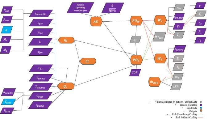
Research, Society and Development, v. 10, n. 9, e59810915006, 2021
 (CC BY 4.0) | ISSN 2525-3409 | DOI: http://dx.doi.org/10.33448/rsd-v10i9.15006

configuration, as well as to calculate the Equivalent Gain in R$ for the situation with cooling.
 In this context, the hypothesis of air intake cooled to 15°C was adopted. The First Law of Thermodynamics was applied,
together with the project data and the monitored process values to simulate the energy transformation through the studied gas
turbines. The information provided by the plant's own weather station is also used to define the most relevant climatic conditions
to be simulated and to create a model to evaluate the operation of the turbines during the period of one year.

2.1 Model Development
 First, an in-house computer model was developed, utilizing MS Excel ®. This model was capable of evaluating the
turbine power output considering both cases: without inlet air cooling ( ) and with inlet air cooling ( ). Process variables
and values were calculated following the aforementioned equations and utilizing real process monitored values. Such model is
capable of providing for the studied turbine, given the input data, the expected power output, the fuel consumption, the cooling
load related to a fixed climatic condition and the annual gain (AG) due to the new cooling system. In other words, given the
ambient temperature and relative humidity (RH) as inputs, the model provides an estimate of the power output, BFG mass flow,
the cooling load necessary to cool the ambient air to 15°C and the expected economic gains coming from the installation of a
new cooler. Figure 5 shows a flow chart representing the simplified architecture of the developed model.

2.2 Model Validation
 The model was validated by comparing its outputs for power output and fuel consumption, considering the case without
cooling, with the information provided by the Elipse® - a software developed by Prosys Engenharia, which is responsible for
monitoring, in real time, the turbine power output and its fuel consumption.
 The reason for utilizing the case without cooling is the observed inefficiency of the evaporative cooler, that is, it was
considered that the inlet air enters the compressor at ambient temperature. Installed sensors confirmed such condition.

 10
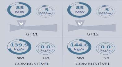
Research, Society and Development, v. 10, n. 9, e59810915006, 2021
 (CC BY 4.0) | ISSN 2525-3409 | DOI: http://dx.doi.org/10.33448/rsd-v10i9.15006

 Figure 5. Computer Model Simplified Architecture.

 Source: Authors.

 The difference between the modelled and monitored values for power output was less than 1%. The fuel consumption
presented by the computer model presented variations ranging from 0% to 3.3% when compared to the abovementioned software.
Table 2 shows the values for turbine power output and fuel consumption, presented by the computer model, for the ambient air
conditions of 29°C and 79% RH, situation observed at the plant on March 1 st, 2018 at 9h00min. Figure 6 shows the values
presented by Elipse® at the same moment.

2.3 Climate data analysis
 After the modelled values were validated, the climate data provided by the power plant’s own weather station for the
whole year of 2017 were analysed. The weather station collects and stores data hourly and such information allowed a detailed
composition considering the variation of the ambient air condition. A total of 8633 measurements, corresponding to the interval
between 01/01/2017 and 12/31/2017, was analysed.

 11
Research, Society and Development, v. 10, n. 9, e59810915006, 2021
 (CC BY 4.0) | ISSN 2525-3409 | DOI: http://dx.doi.org/10.33448/rsd-v10i9.15006

 Table 2. Modelled outputs for 29°C and 79% RH.
 PW 85,127 MW

 ̇ 140,01 kg/s
 Source: Authors.

 Figure 6. Turbines 1 and 2 power output and fuel consumption presented by Elipse® for 29°C and 79% RH.

 Source: Authors.

 Figure 7 indicates the time percentage, through 2017, for the specified ranges of RH. Figure 8 indicates the time
percentage for the specified temperature ranges, considering the RH intervals shown in Figure 7.
 By analysing both graphs it is noticed that, for example, the RH at the power plant site was between 60% and 70% in
24.3% of the measurements taken by the weather station during the year of 2017. Even more, for the measurements where 60%
< RH < 70%, the ambient air temperature was between 20°C and 25°C that for 67.9% of the time.

 Figure 7. Power plant site’s RH conditions during 2017.

 RH AT T H E PO WE R PL ANT IN 2017 (% )
 32,4
 TIME PERCENTAGE (%)

 24,3

 22,63
 11,94

 8,73

 0

 50%
Research, Society and Development, v. 10, n. 9, e59810915006, 2021
 (CC BY 4.0) | ISSN 2525-3409 | DOI: http://dx.doi.org/10.33448/rsd-v10i9.15006

 Figure 8. Predominant temperature intervals for the defined RH ranges.

 PREDOMINANT TEMPERATURE INTERVALS FOR THE DEFINED RH
 RANGES
 Concentration of the temperature measurements for the

 80

 67,9
 70

 60 55
 defined RH Ranges (%)

 48,2 46,7
 50
 42,7

 40 34,4 34,7

 28,4 27,2
 30
 24
 19,6
 20 15,9 16,2
 14
 8,9
 10 4,9
 2,5 2,5 1,6
 0 0,1 0 1,3 1,5 0,8 0 0,97 0 0 0 0 0 0 0
 0
 35°C
Research, Society and Development, v. 10, n. 9, e59810915006, 2021
 (CC BY 4.0) | ISSN 2525-3409 | DOI: http://dx.doi.org/10.33448/rsd-v10i9.15006

 Table 3. Annual Gains for predominant climatic conditions.
 RH 55% Annual Gain (US$)
 ΔT = 10°C @ 25°C 2,211,027.84
 ΔT = 5°C @ 20°C 689,264.86

 RH 65% Annual Gain (US$)
 ΔT = 10°C @ 25°C 2,096,481.81
 ΔT = 5°C @ 20°C 552,929.71
 ΔT = 15°C @ 30°C 2,891,554.33

 RH 75% Annual Gain (US$)
 ΔT = 10°C @ 25°C 1,986,210.39
 ΔT = 15°C @ 30°C 2,700,642.06

 RH 85% Annual Gain (US$)
 ΔT = 10°C @ 25°C 1,880,367.68
 ΔT = 15°C @ 30°C 2,523,695.92

 RH 95% Annual Gain (US$)
 ΔT = 10°C @ 25°C 1,778,794.19
 ΔT = 15°C @ 30°C 2,345,379.76
 Source: Authors.

2.5 Composite annual gain (CAG)
 The CAG is an estimate of the economic gain due to the compressor inlet air cooling to 15°C during the whole year,
considering the climate variations. For its calculation, the values shown in Figure 3, and the data presented in Figures 7 and 8
were utilized. Those values are the coefficients shown at the empirical equation (12) that follows:

 = 1 ( 11 =10° @25° + 12 =10° @25° )@ 55% + 1 ( 11 =10° @25° + 12 =15° @30° +
 13 =5° @20° )@ 65% + 1 ( 11 =10° @25° + 12 =15° @30° )@ 75% + 1 ( 11 =10° @25° +
 12 =15° @30° )@ 85% + 1 ( 11 =10° @25° + 12 =15° @30° )@ 95% (12)

Where:
 • 1 = 0.324 is the coefficient relative to the time percentage that the RH ranged from 50% to 60%, according to Figure
 7.
 • 11 = 0.5 is the coefficient relative to the time percentage the temperature was ranging from 20°C to 25°C, for the RH

 range defined by 1 , according to Figure 8. Value rounded up for convenience.

 • 12 = 0,5 is the coefficient relative to the time percentage the temperature was ranging from 15°C to 20°C, for the RH

 range defined by 1 , according to Figure 8. Value rounded up for convenience.
 • The subscript @RH55% indicates that for the AG calculations the input value of RH = 55% was utilized. This value
 corresponds to the intermediate value of the RH range analysed for the coefficient 1 .

 The values of the coefficients 1 , 11 , 12 , 13 , 1 , 11 , 12 , 1 , 11 , 12 , 1 , 11 , 12 and the meaning of the subscripts
@RH65%, @RH75%, @RH85% e @RH95% are defined similarly. Table 4 shows the utilized values.

 14
Research, Society and Development, v. 10, n. 9, e59810915006, 2021
 (CC BY 4.0) | ISSN 2525-3409 | DOI: http://dx.doi.org/10.33448/rsd-v10i9.15006

 Table 4. CAG Calculation coefficients.

 Coefficient Value
 b1 0.243
 b11 0.679
 b12 0.224
 b13 0.097
 c1 0.119
 c11 0.7
 c12 0.3
 d1 0.087
 d11 0.284
 d12 0.716
 e1 0.227
 e11 0.162
 e12 0.838
 Source: Authors.

 • It is observed that:

 1 + 1 + 1 + 1 + 1 = 1 (13)

and,

 11 + 12 + 13 = 11 + 12 = 11 + 12 = 11 + 12 = 1 (14)

 Both sums must remain with the same result, even when new coefficients are added for model refinement purposes.

3. Results and Discussion
 Figure 9 exhibits the modelled power output gains in MW and in percentage, due to TIAC at the selected conditions.

 15
Research, Society and Development, v. 10, n. 9, e59810915006, 2021
 (CC BY 4.0) | ISSN 2525-3409 | DOI: http://dx.doi.org/10.33448/rsd-v10i9.15006

 Figure 9. Power Output Gains vs RH (MW and %).

 Power Output Gains due TIAC
 8

 7

 6

 5
 Gains [W or %]

 4

 3

 2

 1

 0
 95 90 85 80 75 70 65 60 55 50
 RH [%]

 Gains for cooling from 30°C to 15°C [MW] Gains for cooling from 30°C to 15°C [%]

 Gains for cooling from 25°C to 15°C [MW] Gains for cooling from 25°C to 15°C [%]

 Gains for cooling from 20°C to 15°C [MW] Gains for cooling from 20°C to 15°C [%]

 Source: Authors.

 The power output gain curves associated with the relative humidity behave as expected. Higher gains are obtained in
situations with smaller values of RH; this happens because of the higher energy demand for cooling the ambient air with high
levels of humidity.
 It is also observable that as the cooling ΔT lower, the same happens to the power output gains. Power output gains for
a 15°C cooling (from 30°C to 15°C) are higher than the ones obtained by cooling 10°C (from 25°C to 15°C), which in turn are
higher than the ones obtained by cooling 5°C (from 20°C to 15°C).
 Figure 10 shows First Law Efficiencies for the abovementioned situations and evidences the small influence of TIAC
Technologies on turbine efficiency. These efficiencies are slightly smaller (2-3%) than the ones presented by Ibrahim, et al.,
(2018) and Ersayin & Ozgener, (2015) for a gas turbine cycle operating on natural gas with TIT values similar to the one used
in this study. The power output gains obtained are due to the increased mass flow in the combustion chamber (Ehyaei, et al.,
2015). However, the negative influence of higher values of RH is noticeable for the cases where the cooling is considered.

 16
Research, Society and Development, v. 10, n. 9, e59810915006, 2021
 (CC BY 4.0) | ISSN 2525-3409 | DOI: http://dx.doi.org/10.33448/rsd-v10i9.15006

 Figure 10. First Law Efficiencies.

 First Law Efficiencies and Relative Humidity
 39,00%

 38,50%

 38,00%
 EFFICIENCIES

 T amb = 25°C
 37,50% T amb = 30°C

 37,00% T amb = 20°C
 T amb = 30°C with TIAC
 36,50%
 T amb = 25°C with TIAC
 36,00% T amb = 20°C with TIAC

 35,50%
 50 60 70 80 90 100
 RH (%)

 Source: Authors.

 Table 5 exhibits the CAG for this case study, the Minimum and Maximum Cooling Loads in tons of refrigeration (TR)
- which are the minimum and maximum capacities required for the new chiller and the expected extra BFG Consumption.
 The BFG Extra Consumption was estimated applying analysis and calculations analogous to the CAG.

 Table 5. CAG, Cooling Loads and Extra BFG Consumption.
 Composite Maximum Minimum BFG Extra
 Annual Gain Cooling Load Cooling Load Consumption
 (US$) (TR) (TR) (kg/s)
 1,962,810.49 2800 900 5.83
 Source: Authors.

 The results presented in Table 5 are relative to the operation of only one turbine. Therefore, for the two ALSTOM
GT11N2 turbines, installed at the studied power plant, the CAG would be approximately 3.9 million US$; to achieve that, 2
chillers that meet the range of 900-2800 TR and an additional supply of 10.7 kg/s of BFG would be necessary.
 In terms of electricity generation, the average gain obtained for each turbine is 3.8 MW, adding up to 7.6 MW,
considering both. That is, an increase of 4.22% in generation, related to the optimal condition of 90 MW per turbine. This extra
generation is able to supply the electricity consumed by approximately 32960 Brazilian residences monthly, considering the base
value of 166 kWh/month.
 The 4.22% enhancement agrees with the results presented by Omar Kamal, et al., (2017), achieved through an analysis
using the simulation software GT Pro®, for a natural gas turbine with inlet air cooling through an electric chiller, pointing out to
a 3.86% improvement in the power output. Santos and Andrade, (2012) present gains of approximately 14%, coming from the
installation of an absorption chiller with a higher COP than the one utilized in this study, applied for a smaller natural gas turbine
operating on similar climatic conditions. Noroozian and Bidi, (2016) point out to power output gains of 1.138% due to a 3.2%
cooling in ambient air temperature, through a mechanical chiller.
 The empirical equation utilized for CAG calculations can be as precise as needed. That is, it is possible to create new
coefficients and terms to encompass all the temperature and relative humidity variations. It is also possible to adjust them with

 17
Research, Society and Development, v. 10, n. 9, e59810915006, 2021
 (CC BY 4.0) | ISSN 2525-3409 | DOI: http://dx.doi.org/10.33448/rsd-v10i9.15006

the accuracy relevant to the analyst engineer. The complexity of the analysis and the work involved raise as the equation is
refined.
 The yearly climate variations may also be taken into account, for long-term analysis of investment and returns. In
general, this method can be applied to obtain estimates regarding the economic benefits of applying turbine inlet air cooling
technologies with considerable precision.

4. Conclusion
 Turbine Inlet Air Cooling via absorption chiller, even in high temperatures and high humidity conditions, augments the
power output also for gas turbines using blast furnace gas as fuel, enhancing the economic gains and optimizing the available
energetic resources.
 It is important to study the impact of TIAC Technologies at the combined cycle. It must be verified if there is an increase
in TIT, due to the increased mass flow at the combustion chamber, and its possible effects on turbine operation safety.
Furthermore, it is also recommended to study alternative means of cooling inlet air down to 15°C, as verifying possibilities of
providing the energy necessary for the cooling independently from the gas turbine own generation - considerably enhancing the
power output.
 In conclusion, the hereby explained methodology presents itself as a tool to evaluate economically many other similar
situations. The results obtained through it can be utilized to assist managerial level decisions in integrated steel mills, or any kind
of thermoelectric power plant that operates with gas turbines under resembling environmental conditions, provided the access to
project data, process monitoring values and local climate data. It also allows the evaluation of the reduced environmental impacts
coming from BFG gas flaring.

Acknowledgments
 The authors gratefully acknowledge the support received from Powerplant of Ternium Brazil for the execution of this
work.

References
Alhazmy, M. M., & Najjar, Y. S. H. (2004). Augmentation of gas turbine performance using air coolers. Applied Thermal Engineering, 24(2–3), 415–429.
https://doi.org/10.1016/j.applthermaleng.2003.09.006

Chaker, M, & Meher-Homji, CB. "Evaporative Cooling of Gas Turbine Engines: Climatic Analysis and Application in High Humidity Regions." Proceedings
of the ASME Turbo Expo 2007: Power for Land, Sea, and Air. Volume 3: Turbo Expo 2007. Montreal, Canada. May 14–17, 2007. pp. 761-773.
ASME. https://doi.org/10.1115/GT2007-27866.

Chowdhury, J. I., Hu, Y., Haltas, I., Balta-Ozkan, N., Matthew, G., & Varga, L. (2018). Reducing industrial energy demand in the UK: A review of energy
efficiency technologies and energy saving potential in selected sectors. Renewable and Sustainable Energy Reviews, 94(July), 1153–1178.
https://doi.org/10.1016/j.rser.2018.06.040

Ehyaei, M. A., Tahani, M., Ahmadi, P., & Esfandiari, M. (2015). Optimization of fog inlet air cooling system for combined cycle power plants using genetic
algorithm. Applied Thermal Engineering, 76, 449–461. https://doi.org/10.1016/j.applthermaleng.2014.11.032

Ersayin, E., & Ozgener, L. (2015). Performance analysis of combined cycle power plants: A case study. Renewable and Sustainable Energy Reviews, 43, 832–
842. https://doi.org/10.1016/j.rser.2014.11.082

Geerdes, M., Toxopeus, H., Vaynshteyn, R., & Van Laar, R. (2009). The future of BF ironmaking - lowering hot metal costs with innovative processes. Millenium
Steel, 29–32. file://ce/rd_organisation/PRC-ISC/Common/03. Technology/01. Literature/POS3096 - Geerdes et al - The future of BF ironmaking - lowering hot
metal costs with innovative processes.pdf

Green, J., Strickland. A., Kimsesiz, E., Temucin, I., (1996). Blast furnace gas fired boiler for Eregli Iron & Steel Works (Erdemir). Turkey. Proceedings of the
American Power Conference, p. 1218-1223.

He, K., & Wang, L. (2017). A review of energy use and energy-efficient technologies for the iron and steel industry. Renewable and Sustainable Energy Reviews,
70(June 2015), 1022–1039. https://doi.org/10.1016/j.rser.2016.12.007

 18
Research, Society and Development, v. 10, n. 9, e59810915006, 2021
 (CC BY 4.0) | ISSN 2525-3409 | DOI: http://dx.doi.org/10.33448/rsd-v10i9.15006

Ibrahim, T. K., Mohammed, M. K., Awad, O. I., Abdalla, A. N., Basrawi, F., Mohammed, M. N., Najafi, G., & Mamat, R. (2018). A comprehensive review on
the exergy analysis of combined cycle power plants. Renewable and Sustainable Energy Reviews, 90(March), 835–850.
https://doi.org/10.1016/j.rser.2018.03.072

Ibrahim, T. K., Rahman, M. M., & Abdalla, A. N. (2011). Improvement of gas turbine performance based on inlet air cooling systems: A technical review.
International Journal of Physical Sciences, 6(4), 620–627. https://doi.org/10.5897/IJPS10.563

Jeffs, E. (2008). Generating Power at High Efficiency: Combined Cycle Technology for Sustainable Energy. UK: Woodhead Publishing. 1ª edição (8 maio
2008).

Kakaras, E., Doukelis, A., & Karellas, S. (2004). Compressor intake-air cooling in gas turbine plants. Energy, 29(12-15 SPEC. ISS.), 2347–2358.
https://doi.org/10.1016/j.energy.2004.03.043

Modesto, M., & Nebra, S. A. (2009). Exergoeconomic analysis of the power generation system using blast furnace and coke oven gas in a Brazilian steel mill.
Applied Thermal Engineering, 29(11–12), 2127–2136. https://doi.org/10.1016/j.applthermaleng.2008.12.033

Noroozian, A., & Bidi, M. (2016). An applicable method for gas turbine efficiency improvement. Case study: Montazar Ghaem power plant, Iran. Journal of
Natural Gas Science and Engineering, 28, 95–105. https://doi.org/10.1016/j.jngse.2015.11.032

Omar Kamal, S. N., Salim, D. A., Mohd Fouzi, M. S., Hong Khai, D. T., & Yusri Yusof, M. K. (2017). Feasibility Study of Turbine Inlet Air Cooling using
Mechanical Chillers in Malaysia Climate. Energy Procedia, 138, 558–563. https://doi.org/10.1016/j.egypro.2017.10.159

Peacey, J.G. & Davenport, W.G. (1979). The Iron Blast Furnace: Theory and Practice. Pergamon Press.

Pereira, A.S., Shitsuka, D.M., Parreira, F.J. & Shitsuka, R. (2018). Metodologia da pesquisa científica: UFSM.

Poullikkas, A. (2005). An overview of current and future sustainable gas turbine technologies. Renewable and Sustainable Energy Reviews, 9(5), 409–443.
https://doi.org/10.1016/j.rser.2004.05.009

Pugh, D., Giles, A., Hopkins, A., O’Doherty, T., Griffiths, A., & Marsh, R. (2013). Thermal distributive blast furnace gas characterisation, a steelworks case
study. Applied Thermal Engineering, 53(2), 358–365. https://doi.org/10.1016/j.applthermaleng.2012.05.014

Ryzhkov, A. F., Levin, E. I., Filippov, P. S., Abaimov, N. A., & Gordeev, S. I. (2016). Making More Efficient Use of Blast-Furnace Gas at Russian Metallurgical
Plants. Metallurgist, 60(1–2), 19–30. https://doi.org/10.1007/s11015-016-0247-1

Santos, A. P., & Andrade, C. R. (2012). Analysis of gas turbine performance with inlet air cooling techniques applied to Brazilian sites. Journal of Aerospace
Technology and Management, 4(3), 341–353. https://doi.org/10.5028/jatm.2012.04032012

Shi, X., Agnew, B., Che, D., & Gao, J. (2010). Performance enhancement of conventional combined cycle power plant by inlet air cooling, inter-cooling and
LNG cold energy utilization. Applied Thermal Engineering, 30(14–15), 2003–2010. https://doi.org/10.1016/j.applthermaleng.2010.05.005

Shirazi, A., Najafi, B., Aminyavari, M., Rinaldi, F., & Taylor, R. A. (2014). Thermal-economic-environmental analysis and multi-objective optimization of an
ice thermal energy storage system for gas turbine cycle inlet air cooling. Energy, 69, 212–226. https://doi.org/10.1016/j.energy.2014.02.071

Shukla, A. K., & Singh, O. (2016). Performance evaluation of steam injected gas turbine based power plant with inlet evaporative cooling. Applied Thermal
Engineering, 102, 454–464. https://doi.org/10.1016/j.applthermaleng.2016.03.136

Soares, C. (2015). Gas Turbines: A Handbook of Air, Land and Sea Applications. Butterworth-Heinemann; (2a ed.).

Temir, G., & Bilge, D. (2004). Thermoeconomic analysis of a trigeneration system. Applied Thermal Engineering, 24(17–18), 2689–2699.
https://doi.org/10.1016/j.applthermaleng.2004.03.014

Toyoaki KOMORI, Hiroyuki HARA, H. A. and Y. K. (2003). Design for F Class Blast Furnace Gas Firing 300 MW Gas Turbine Combined Cycle Plant.
Proceedings of the International Gas Turbine Congress, c, 1–8.

Uribe-Soto, W., Portha, J. F., Commenge, J. M., & Falk, L. (2017). A review of thermochemical processes and technologies to use steelworks off-gases.
Renewable and Sustainable Energy Reviews, 74(March), 809–823. https://doi.org/10.1016/j.rser.2017.03.008

Yao, H., Sheng, D., Chen, J., Li, W., Wan, A., & Chen, H. (2013). Exergoeconomic analysis of a combined cycle system utilizing associated gases from steel
production process based on structural theory of thermoeconomics. Applied Thermal Engineering, 51(1–2), 476–489.
https://doi.org/10.1016/j.applthermaleng.2012.09.019

 19
You can also read


