Asynchronous indoor positioning system based on visible light communications
←
→
Page content transcription
If your browser does not render page correctly, please read the page content below
Asynchronous indoor positioning
                 system based on visible light
                 communications

                 Weizhi Zhang
                 M. I. Sakib Chowdhury
                 Mohsen Kavehrad

Downloaded From: https://www.spiedigitallibrary.org/journals/Optical-Engineering on 05 Nov 2021
Terms of Use: https://www.spiedigitallibrary.org/terms-of-use
Optical Engineering 53(4), 045105 (April 2014)

                Asynchronous indoor positioning system based on
                visible light communications
                Weizhi Zhang,* M. I. Sakib Chowdhury, and Mohsen Kavehrad
                Department of Electrical Engineering, Pennsylvania State University, University Park, Pennsylvania 16802

                              Abstract. Indoor positioning has become an attractive research topic within the past two decades. However, no
                              satisfying solution has been found with consideration of both accuracy and system complexity. Recently,
                              research on visible light communications (VLC) offer new opportunities in realizing accurate indoor positioning
                              with relatively simple system configuration. An indoor positioning system based on VLC technology is intro-
                              duced, with no synchronization requirement on the transmitters. Simulation results show that, with over 95%
                              confidence, the target receiver can be located with an accuracy of 5.9 cm, assuming indirect sunlight exposure
                              and proper installation of light-emitting diode bulbs. © 2014 Society of Photo-Optical Instrumentation Engineers (SPIE) [DOI: 10.1117/
                              1.OE.53.4.045105]

                              Keywords: indoor positioning system; visible light communications; light-emitting diode.
                              Paper 140049 received Jan. 14, 2014; revised manuscript received Mar. 24, 2014; accepted for publication Mar. 25, 2014; published
                              online Apr. 25, 2014.

                1 Introduction                                                                        VLC-based techniques employ fluorescent lamps and
                Indoor positioning is a research area that is gaining lots of                     light-emitting diodes (LEDs). VLC-based techniques have
                attention recently. Its applications cover a wide area where                      the advantage that the sources do not produce EM interfer-
                the technology can be incorporated into consumer electron-                        ence, and thus can be used in environments where RF is pro-
                ics products. For example, in the case of in-house navigation,                    hibited. Most of the VLC-based techniques use LEDs as the
                indoor positioning technology can be utilized by handheld                         light source, since they can be modulated more easily com-
                products to provide location identification, and thus guide                       pared with fluorescent lamps and hence, location data can be
                users inside large museums and shopping malls. Another                            transmitted in a simpler way. Moreover, LEDs are currently
                potential application is location detection of products inside                    being installed in most buildings, especially larger ones, e.g.,
                large warehouses where indoor positioning can automate                            museums and shopping malls, as the primary lighting source
                some of the inventory management processes. Indoor posi-                          instead of fluorescent lamps since they have the advantage of
                tioning techniques, if installed in consumer electronic prod-                     much longer life and lower operating cost though the initial
                ucts, can also be utilized to provide location-based services                     fixed cost is still higher. So, proposed indoor positioning
                and advertisements to the users. For the attractive applica-                      techniques that are based on VLC and LEDs are excellent
                tions mentioned above, many giant corporations are devoting                       options. This article focuses on VLC technology based on
                their research and development resources into indoor posi-                        LEDs. The accuracy achieved is also better using VLC tech-
                tioning technologies.                                                             nology than RF-based techniques as is shown in this article.
                    But, rapid positioning indoors are difficult to achieve by                        There are different positioning algorithms that have
                global positioning system (GPS) because radio signals from                        been used in the literature and can be broadly divided into
                                                                                                  three categories: triangulation, scene analysis, and proximity,
                GPS satellites do not penetrate well through walls of large
                                                                                                  regardless of the light sources.6–13 Triangulation is the gen-
                buildings. Hence, users using GPS indoors face large
                                                                                                  eral name of positioning techniques that use the geometric
                positioning errors as well as not being able to connect to
                                                                                                  properties of triangles for location estimation, and consist
                GPS satellites at all. To circumvent this situation, two pos-
                                                                                                  of mainly two branches: lateration and angulation.
                sible alternatives exist, namely radio frequency (RF)-based
                                                                                                  Lateration methods estimate the target location by measuring
                techniques and visible light communications (VLC)-based
                                                                                                  its distances from multiple reference points. In VLC-based
                techniques.
                                                                                                  positioning techniques, reference points are the light sources
                    RF-based techniques include, but are not limited to,
                                                                                                  and the target is the optical receiver. The distance is mea-
                the following technologies: wireless local area network,
                                                                                                  sured indirectly by measuring the received signal strength
                radio-frequency identification, cellular, ultrawide band, blue-
                                                                                                  (RSS), time-of-arrival (TOA), or time-difference-of-arrival
                tooth,1–4 etc. These methods deliver positioning accuracies
                                                                                                  (TDOA). This article uses RSS-based positioning method
                from tens of centimeters to several meters.5 But this amount
                                                                                                  as it is found to achieve better accuracy than other methods.
                of accuracy is not sufficient for the applications described
                                                                                                  Zhou et al. reported an accuracy of 0.5 mm using RSS-based
                above. Apart from the relatively poor accuracy of indoor posi-                    technique.7 TOA-based methods require complete synchro-
                tioning achievable by RF-based techniques, they also add to                       nization among the clocks of transmitters and receiver,
                the electro-magnetic (EM) interference. For these reasons, the                    and have not been used in VLC-based techniques, but are
                techniques based on VLC are gaining more attraction.                              used for GPS. TDOA-based methods can also be used in

                *Address all correspondence to: Weizhi Zhang, E-mail: wuz113@psu.edu              0091-3286/2014/$25.00 © 2014 SPIE

                Optical Engineering                                                       045105-1                                          April 2014   •   Vol. 53(4)

Downloaded From: https://www.spiedigitallibrary.org/journals/Optical-Engineering on 05 Nov 2021
Terms of Use: https://www.spiedigitallibrary.org/terms-of-use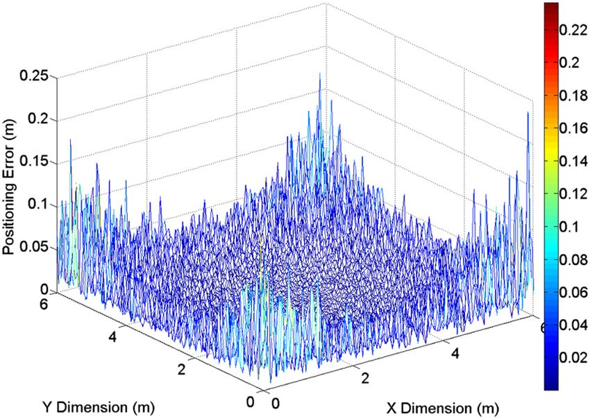
Zhang, Chowdhury, and Kavehrad: Asynchronous indoor positioning system based on visible light communications

                VLC-based systems, while in most cases the TDOA infor-
                mation is acquired indirectly.8,9 These methods require syn-
                chronization among the transmitters.
                    The second category of triangulation methods, angula-
                tion, measure angles relative to several reference points
                (angle of arrival, AOA). Location estimation is then per-
                formed by finding intersection of direction lines, which
                are radii range from reference points to the target.10 The
                widely deployed front-facing cameras, which are inherently
                imaging receivers, on smartphones and tablets have brought
                opportunities for this method to become realistic on mobile
                consumer electronics. However, due to the limited field-of-
                view (FoV) of these cameras, to reach good performance
                for a real system, a very dense lighting grid is required;
                otherwise, the system can only be deployed inside rooms
                with very high ceilings.                                                                             Fig. 1 System configuration.
                    Scene analysis refers to a group of positioning algorithms
                that matches measured information to a previously calibrated
                database, thus omitting the computation. TOA, TDOA, RSS,                          links is the DC gain. In LOS links, the channel gain can be
                and AOA can be used to collect the measurement data.                              estimated fairly accurately by considering only the LOS
                However, these methods require accurate precalibration                            propagation path. The channel DC gain is expressed as
                for a specific environment and cannot be instantly deployed                                 mþ1
                in a new setting. RSS information is used as the measurement                                     A · cosm ðϕÞ · T s ðψÞ · gðψÞ · cosðψÞ; 0 ≤ ψ ≤ Ψc
                                                                                                  Hð0Þ ¼ 2πd2                                                       ;
                data by Hann et al.11 and an accuracy of 0.651 cm is reported.                               0;                                          ψ > Ψc
                    Proximity method is very simple in the sense that it relies                                                                                  (1)
                only upon a grid of reference points, each having a well-
                known position; when a target collects signal from a single                       where A is the physical area of the detector, ψ is the angle of
                source, it is considered to be colocated with the source. Thus,                   incidence with respect to the receiver axis, T s ðψÞ is the gain
                the accuracy is no more than the resolution of the grid itself.                   of optical filter, gðψÞ is the concentrator gain, Ψc is the con-
                Lee et al.12,13 proposed and experimentally demonstrated                          centrator FoV semi-angle, ϕ is the angle of irradiance with
                a proximity-based indoor positioning system, where, apart                         respect to the transmitter perpendicular axis, and d is the dis-
                from positioning provided by the visible light LEDs,                              tance between transmitter and receiver, as shown in Fig. 2.
                a Zigbee wireless network is used to transmit the location                           The Lambertian order m is given by m ¼ − ln 2∕ ln
                information to the observer node, as well as to extend the                        ðcos Φ1∕2 Þ, where Φ1∕2 is the half power angle of the
                working range.                                                                    LED bulb. The received optical power is given by:
                    As mentioned earlier, this article uses RSS-based triangu-                    Pr ¼ Hð0Þ · Pt , where Pt denotes the transmitted optical
                lation method. One novel aspect of the technique described                        power from the LED bulb.
                in this article is that the transmitters do not require synchro-
                nization at all, implying no connections are needed among
                the transmitters. Thus, the system proposed in this article                       2.2 Channel Multiaccess Method
                is easier and cheaper to deploy inside different indoor                           As shown in Fig. 1, there are multiple transmitters and one
                environments.                                                                     receiver in this system. Therefore, the channel multiaccess
                    The rest of the article is organized as follows. Section 2                    problem has to be solved. Previous LED-based indoor posi-
                describes the indoor optical wireless channel, the asynchro-                      tioning methods usually use time division multiaccess as a
                nous channel multiplexing method, and the positioning                             solution, which requires perfect synchronization among all
                method. Section 3 describes the simulation model and
                includes a signal-to-noise (SNR) analysis and simulation
                results and discussion on them. Section 4 contains the con-
                clusion of the article.

                2 System Design and Positioning Algorithm
                2.1 Indoor Optical Wireless Channel
                As shown in Fig. 1, the system contains a set of LED bulbs
                on the ceiling and a mobile terminal. LED bulbs function
                as transmitters, sending different hardware IDs related to
                their physical locations. An optical receiver inside the
                mobile terminal extracts the location information to perform
                positioning.
                   The optical channels considered in this article are all line-
                of-sight (LOS) links. Following the research done by Kahn
                and Barry,14 the most important quantity to characterize such                                           Fig. 2 Channel model.

                Optical Engineering                                                       045105-2                                            April 2014   •   Vol. 53(4)

Downloaded From: https://www.spiedigitallibrary.org/journals/Optical-Engineering on 05 Nov 2021
Terms of Use: https://www.spiedigitallibrary.org/terms-of-use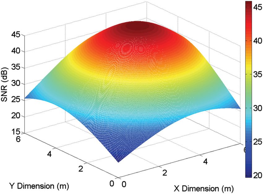
Zhang, Chowdhury, and Kavehrad: Asynchronous indoor positioning system based on visible light communications

                Fig. 3 Basic framed slotted additive link on-line Hawaii system
                (ALOHA) protocol (three transmitters, four slots per frame).

                LEDs, resulting in higher deployment cost and time. Here, an
                asynchronous channel multiplexing method called basic-
                framed slotted ALOHA6,15 (BFSA) is proposed. BFSA is
                a variant of basic additive link on-line Hawaii system
                (ALOHA) protocol; it defines a frame structure containing
                a fixed number of time slots. Each transmitter randomly
                selects a slot within a frame and transmits its location
                data in that slot. As each of the transmitters randomly selects
                a slot, it is possible that sometimes there is overlap among                      Fig. 4 Probability of successful transmission versus number of slots
                them in time. Such overlap is assumed as a detection failure.                     per frame, n ¼ 4.
                Figure 3 shows an example of the working principle of
                BFSA protocol. There are 3 transmitters and 4 slots and
                their operation are shown in two frames. In the first                             difference between synchronous and asynchronous systems
                                                                                                  is negligible.
                frame, the transmitters all select different slots and the
                                                                                                     Now, BFSA protocol requires bandwidth for individual
                receiver will be able to distinguish their signals individually
                                                                                                  transmitter to be N times of the originally needed.
                as there is no interference. However, in the second frame,
                                                                                                  However, the data rate this system is working at is not
                transmitter 1 and 2 both have selected slot 3. Due to this,
                                                                                                  very high; so, a relatively large N can be chosen to ensure
                the receiver will not be able to distinguish their individual                     successful transmissions for most of the time.
                signals for their mutual interference and a detection failure                        Suppose 128 bits are used to represent the hardware ID
                is expected in that frame. It should also be noted that since                     for individual LED bulbs, plus an 8-bit beginning flag, an
                the transmitters are not synchronized, the exact start time of                    8-bit ending flag and a segment of 16-bit CRC to form a
                transmission in each slot by the transmitters is different,                       packet that is to be transmitted within a frame. The system
                which may lead to overlap among their transmissions                               will perform positioning 10 times per second and use a frame
                even if they select adjacent slots. Here, detection failure is                    structure containing 400 slots. The required date rate is then
                supposed as a result of any overlap, even partial.                                given by
                    The traditional factor used to evaluate the performance of
                ALOHA-based protocols is throughput. Throughput is                                400 × ð128 þ 8 þ 8 þ 16Þbit∕0.1 s ¼ 640 Kbps:                       (3)
                defined as the rate of successful transmission by the nodes.
                However, it cannot be used in this system for evaluation pur-                        This speed is definitely deliverable even with available
                poses because the receiver has to receive all signals from                        off-the-shelf LEDs. On the other hand, with 128 bits the sys-
                different LEDs to estimate its position. In other words, suc-                     tem will be able to label 2128 ¼ 3.4 × 1038 LEDs, which is
                cessful reception of only one signal from one transmitter is                      far more than actually needed. Therefore, this indoor posi-
                not enough for the receiver to localize itself. Therefore, the                    tioning system will work universally at every place where
                only factor to consider here is the probability of successful                     supporting LEDs are installed.
                transmission from all transmitters to a given receiver.
                    As mentioned earlier, it is assumed that any overlap                          2.3 Positioning Algorithm
                among signals will lead to a detection failure. Under this
                assumption, the probability of successful transmission                            In the system, the RSS information of received signal will
                (Psuccess ) in BFSA protocol, given total synchronization, is                     be used to estimate the receiver’s distances from transmitters
                                                                                                  on the ceiling, after which the receiver will be located by
                                                                                                triangulation.
                                 N
                Psuccess ¼           ∕N n ;                                             (2)           Each of the LED bulbs will simply transmit its own code,
                                 n                                                                modulated in on-off-keying (OOK) format. An LED bulb
                                                                                                  will use only one slot within the duration of one frame
                where n is the number of transmitters and N is the number of                      length, while delivering output at a constant power level
                slots in a frame.                                                                 for illumination purposes. Therefore, the receiver will be
                   When n is bigger than 2, there is no closed mathematical                       receiving only one modulated signal at one instance for
                form of Psuccess for asynchronous systems. But difference in                      most of the time. The OOK modulation used in this system
                performance between synchronous and asynchronous sce-                             has a modulation depth of 12.5% to minimize the flickering
                narios can be obtained by running computer simulations.                           problem.16 Since the optical emitted power is linearly pro-
                Figure 4 shows Psuccess versus the number of slots per                            portional to the amplitude of the electrical signal, the differ-
                frame, N, for four transmitters. It can be seen that when                         ence in transmitted power between logical 0s and 1s at the
                N is large enough (e.g., N ≥ 200), the performance                                transmitter side is given as

                Optical Engineering                                                       045105-3                                             April 2014   •   Vol. 53(4)

Downloaded From: https://www.spiedigitallibrary.org/journals/Optical-Engineering on 05 Nov 2021
Terms of Use: https://www.spiedigitallibrary.org/terms-of-use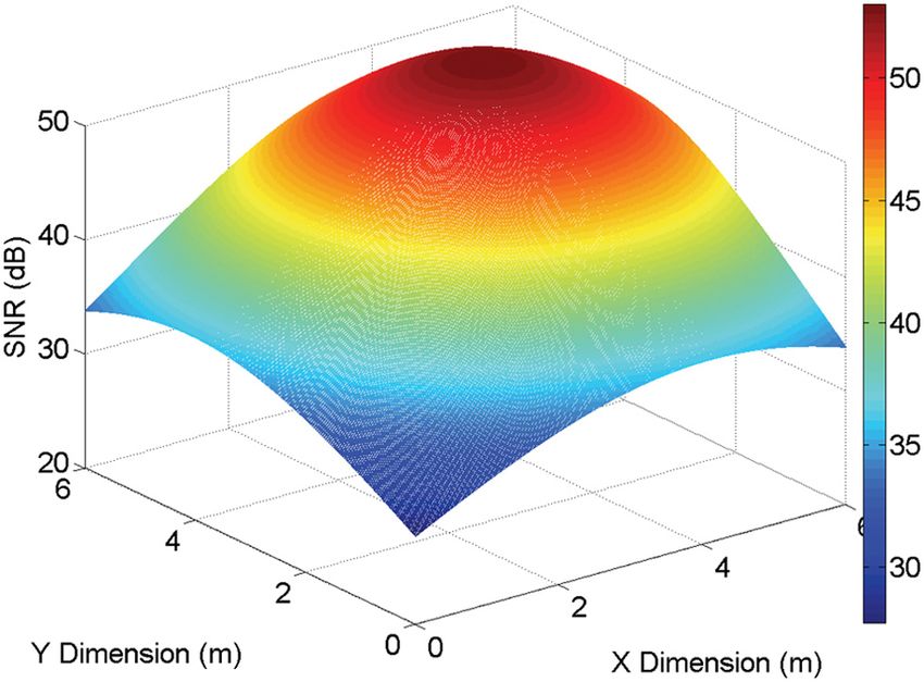
Zhang, Chowdhury, and Kavehrad: Asynchronous indoor positioning system based on visible light communications
Pdiff ¼ ηOOK Pconst ; (4) 2.4 Linear Least Square Estimation
To estimate the unknown position of the receiver by knowing
where ηOOK is the modulation depth of the OOK modulation the distances from several reference points (transmitters’
and equal to 0.125 in this article. horizontal coordinates), linear least square estimation is
Pconst is the optical power emitted from LED bulb without used since it will provide the most reliable estimation
modulation. Therefore, the difference at the receiver side when there are a small number of reference points.
Pdiff r will be given by After the estimated horizontal distance between the
receiver and each of the three transmitters (denoted as A,
mþ1 B, and C) is obtained, a set of three quadratic equations
Pdiff r ¼ Hð0Þ · Pdiff ¼ A · cosm ðϕÞ · T s ðψÞ
2πd2 as follows is formed:
· gðψÞ · cosðψÞ · Pdiff : (5)
ðx − xA Þ2 þ ðy − yA Þ2 ¼ d2A ; (12)
Given the receiver’s FoV is large enough so that 0 ≤ ψ ≤
Ψc always holds, the distance between the transmitter and the ðx − xB Þ2 þ ðy − yB Þ2 ¼ d2B ; (13)
receiver dest can be estimated by measuring Pdiff r at the
receiver:6
sffiffiffiffiffiffiffiffiffiffiffiffiffiffiffiffiffiffiffiffiffiffiffiffiffiffiffiffiffiffiffiffiffiffiffiffiffiffiffiffiffiffiffiffiffiffiffiffiffiffiffiffiffiffiffiffiffiffiffiffiffiffiffiffiffiffiffiffiffiffiffiffiffiffiffiffiffiffiffiffiffiffiffiffiffiffiffiffiffiffiffiffiffiffiffiffiffi ðx − xC Þ2 þ ðy − yC Þ2 ¼ d2C ; (14)
ðm þ 1ÞA · cosm ðϕÞ · T s ðψÞ · gðψÞ · cosðψÞ · Pdiff
dest ¼ : where ½xA ; xB ; xC and ½yA ; yB ; yC are the coordinates of
2π · Pdiff r LED bulbs in X and Y axes, ½dA ; dB ; dC are the horizontal
(6) distances from the receiver to LED bulbs, ðx; yÞ is the receiv-
er’s position to be estimated.
The optical concentrator gain gðψÞ for a compound para- To get one estimation for the receiver’s position ðx; yÞ, the
bolic concentrator is given as14 following equation group has to be solved:
n2C 2xðxA − xC Þ þ x2C − x2A þ 2yðyA − yC Þ þ y2C − y2A ¼ d2C − d2A
gðψÞ ¼ ; 0 ≤ ψ ≤ Ψc ; :
sin2 ðΨc Þ (7) 2xðxB − xC Þ þ x2C − x2B þ 2yðyB − yC Þ þ y2C − y2B ¼ d2C − d2B
0; ψ > Ψc
(15)
where nC denotes the refractive index of the concentrator.
If more than three reference points are involved, all the
Assuming both the receiver axis and the transmitter axis
equation groups formed by any three quadratic equations
to be perpendicular to the ceiling, the following equations
are first solved, after which the estimations are averaged
hold:
out to obtain the final estimated position of the receiver.
qffiffiffiffiffiffiffiffiffiffiffiffiffiffiffiffiffiffiffiffiffiffiffiffi
dest ¼ d2est−xy þ H2 ; (8) 3 Performance Evaluation
3.1 Simulation Model
cosðϕÞ ¼ cosðψÞ ¼ H∕dest ; (9) The system configuration is depicted in Fig. 5. As shown,
there are four LED bulbs located on the ceiling. Since the
where dest−xy is the estimated horizontal distance between the LEDs within one bulb are colocated and modulated by
transmitter and the receiver and H is the vertical distance the same circuit, they will perform as a single optical
between the ceiling and the receiver. All the LEDs are char- transmitter.
acterized as first-order Lambertian light sources; so, m ¼ 1. In the proposed system, each of these four LED bulbs will
Also, to simplify the calculation, the transmission of optical transmit a unique code assigned to them (first four bits are
filter and the gain of optical concentrator are combined into 0111, 1011, 1101, 1110, respectively, the rest 124 bits are
one gain: same), modulated in OOK format. The receiver is located
within the horizontal plane of 1-m height. Parameters
T s ðψÞ · gðψÞ ¼ G; (10) used in the simulation are shown in Table 1.
where G is a constant related to characteristics of filter and 3.2 SNR Analysis
concentrator. Consequently,
Before running the simulation, the SNR is calculated to
vffiffiffiffiffiffiffiffiffiffiffiffiffiffiffiffiffiffiffiffiffiffiffiffiffiffiffiffiffiffiffiffiffiffiffiffiffiffiffiffiffiffiffiffiffiffiffiffiffiffiffiffiffiffiffi
ffi
usffiffiffiffiffiffiffiffiffiffiffiffiffiffiffiffiffiffiffiffiffiffiffiffiffiffiffiffiffiffiffiffiffiffiffiffiffiffiffi ffi examine the effects of it on the system. The signal compo-
u A · G · P · H 2 nent is given by
dest−xy ¼ t diff
− H2 : (11)
π · Pdiff r
S ¼ γ 2 P2diff r ; (16)
So long as the positions of LEDs related to different codes where γ is the detector responsivity and Pdiff r is given
are known to the receiver, by collecting signals coming from by Eq. (5).
at least three LEDs, the receiver will be able to use triangu- Following Komine and Nakagawa’s research,17 the noise
lation to determine its current position on a two-dimen- is Gaussian having a total variance N, which is the sum of
sional plane. contribution from shot noise and thermal noise, given by
Optical Engineering 045105-4 April 2014 • Vol. 53(4)
Downloaded From: https://www.spiedigitallibrary.org/journals/Optical-Engineering on 05 Nov 2021
Terms of Use: https://www.spiedigitallibrary.org/terms-of-use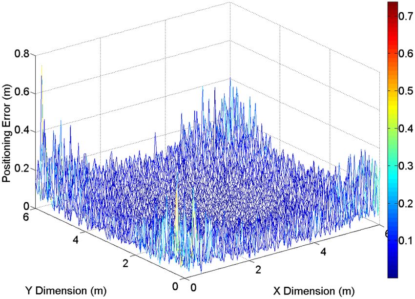
Zhang, Chowdhury, and Kavehrad: Asynchronous indoor positioning system based on visible light communications
factor, I 2 ¼ 0.562.17 A p-i-n/field-effect transistor (FET)
transimpedance receiver is used and the noise contributions
from gate leakage current and 1∕f noise are negligible.19
Prec is given by
X
4
Prec ¼ Hi ð0ÞPi ; (19)
i¼1
where H i ð0Þ and Pi are the channel DC gain and instanta-
neous emitted power for the i’th LED bulb, respectively.
On the other hand, the thermal noise variance is given by
8πkT K 16π 2 kT K Γ 2 2
σ 2thermal ¼ ηAI 2 B2 þ η A I 3 B3 ; (20)
Go gm
where the two terms represent feedback-resistor noise and
FET channel noise. Here, k is Boltzmann’s constant, T K
is absolute temperature, Go is the open-loop voltage gain,
Fig. 5 System model used in simulation.
η is the fixed capacitance of photodetector per unit area,
Γ is the FET channel noise factor, gm is the FET transcon-
ductance, and I 3 ¼ 0.0868.
In the simulation, the following values are used:20
N ¼ σ 2shot þ σ 2thermal : (17) T K ¼ 295 K, Go ¼ 10, gm ¼ 30 mS, Γ ¼ 1.5, and
η ¼ 112 pF∕cm2 . Parameters of the receiver are listed in
The shot noise variance is given by Table 2. To evaluate the impact of SNR on the system, a dis-
tribution map of SNR with respect to LED bulb D, which is
located at (4, 4, 4) (m), is shown in Fig. 6, assuming direct
σ 2shot ¼ 2qγðPrec ÞB þ 2qI bg I 2 B; (18) sunlight exposure and in Fig. 7, assuming indirect sunlight
exposure.
where q is the electronic charge, B is equivalent noise As can be observed from the figures, the SNR is about
bandwidth, which is equal to the modulation bandwidth 10 dB lower in direct sunlight exposed room environment
here, I bg is background current, whose traditional value is for the same location, compared with indirect sunlight expo-
5100 μA given direct sunlight exposure and 740 μA assum- sure. This is mainly because of the increased contribution
ing indirect sunlight exposure18 and the noise bandwidth from shot noise to the total noise level. Besides, it is
shown in both figures that the signal transmitted from
LED bulb D experiences a very low SNR at the room corner
Table 1 Parameters in simulation. (0, 0, 0) (m). This will be translated into relatively large error
in estimating the distance between the LED bulb D and
the receiver when it is located at the corner, in other
Parameter Value words, the system performance will be downgraded when
Room dimension ðL × W × HÞ 6 × 6 × 4 m3 the user is far away from the LED bulbs.
Power of light-emitting diode 16-W each
(LED) bulb (P const ) 3.3 Results and Discussions
The system performance is evaluated when the receiver is at
Positions of LED bulbs A(2, 2, 4) a fixed height of 1 m. For the receiver positions, 0.05 m is set
ðx ; y ; zÞ (m)
B(4, 2, 4) as the resolution, meaning that the Euclidean distance
between adjacent positions of the receiver is 0.05 m.
C(2, 4, 4)
D(4, 4, 4)
Table 2 Receiver parameters.
Codes used by LED bulbs A(0 1 1 1) (The remaining
124 bits are same)
B(1 0 1 1) Parameter Value
C(1 1 0 1) Field-of-view (Ψc ) (half angle) 70 deg
D(1 1 1 0) Physical area of photo-detector (A) 1.0 cm2
Modulation depth (ηOOK ) 12.5% Gain of optical filter (T s ðψÞ) 1.0
Modulation bandwidth (B) 640 KHz Refractive index of optical concentrator (n C ) 1.5
Receiver height 1m O/E conversion efficiency (γ) 0.54 (A∕W)
Optical Engineering 045105-5 April 2014 • Vol. 53(4)
Downloaded From: https://www.spiedigitallibrary.org/journals/Optical-Engineering on 05 Nov 2021
Terms of Use: https://www.spiedigitallibrary.org/terms-of-use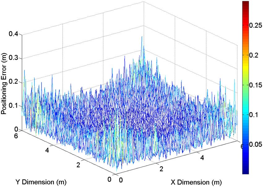
Zhang, Chowdhury, and Kavehrad: Asynchronous indoor positioning system based on visible light communications
Fig. 6 Signal-to-noise (SNR) distribution for light-emitting diode Fig. 9 Positioning error (in units of meter) distribution under indirect
(LED) bulb D (direct sunlight exposure). sunlight exposure.
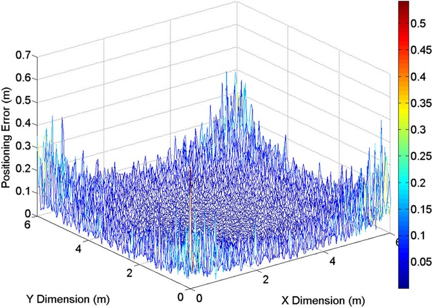
Figure 8 shows the positioning error distribution in the pres-
ence of direct sunlight exposure and Fig. 9 depicts the result
when indirect sunlight exposure is assumed.
As expected, the positioning errors are relatively small
for the majority of the room area, but become significantly
large when the receiver approaches corners. Moreover, the
positioning errors obtained with indirect sunlight exposure
are much smaller compared with direct sunlight exposure
situation, which is a more noisy environment. To directly
compare the difference between these two scenarios, the his-
tograms of positioning errors are shown, respectively, in
Figs. 10 and 11.
To assess the performance of a positioning system more
practically, precision, which indicates how the system con-
sistently delivers a certain level of service within a long time-
scale (i.e., over many trials), is widely employed.
Generally, the cumulative distribution function (CDF) of
positioning error is used to evaluate the precision. By taking
Fig. 7 SNR distribution for LED bulb D (indirect sunlight exposure). the effects of BFSA protocol into consideration, using
a frame structure containing 400 slots per frame for simula-
tion, the precision curve (CDF curve of positioning error) of
this system is obtained and shown in Fig. 12.
Fig. 8 Positioning error (in units of meter) distribution under direct
sunlight exposure. Fig. 10 Histogram of positioning error (direct sunlight exposure).
Optical Engineering 045105-6 April 2014 • Vol. 53(4)
Downloaded From: https://www.spiedigitallibrary.org/journals/Optical-Engineering on 05 Nov 2021
Terms of Use: https://www.spiedigitallibrary.org/terms-of-use
Zhang, Chowdhury, and Kavehrad: Asynchronous indoor positioning system based on visible light communications

                                                                                                              Table 3 Parameters in extended simulation.

                                                                                                  Parameter                                          Value

                                                                                                  Room dimension ðL × W × HÞ                      6 × 6 × 4 m3

                                                                                                  Power of LED bulb (P const )                    16-W each

                                                                                                  Positions of LED                              A(2, 2, 4.005)
                                                                                                  bulbs ðx; y; zÞ (m)
                                                                                                                                                  B(3.98, 2, 4)

                                                                                                                                              C(2.01, 4.005, 4)

                                                                                                                                               D(4, 4.01, 3.99)

                                                                                                  Codes used by LED bulbs            A(0 1 1 1)         (The remaining
                                                                                                                                                      124 bits are same)
                                                                                                                                     B(1 0 1 1)
                 Fig. 11 Histogram of positioning error (indirect sunlight exposure).
                                                                                                                                     C(1 1 0 1)

                                                                                                                                     D(1 1 1 0)

                                                                                                  Modulation depth (ηOOK )                           12.5%

                                                                                                  Modulation bandwidth (B)                         640 KHz

                                                                                                  Maximum orientation angle of                       5 deg
                                                                                                  the receiver

                                                                                                  Receiver height                                     1m

                                                                                                      As we can see, the mean of positioning errors, in both
                                                                                                  situations, increases compared with the values shown in
                                                                                                  Figs. 10 and 11, but not dramatically. Therefore, the perfor-
                                                                                                  mance of this system will remain within the same level, even
                                                                                                  if the LED bulbs involved are installed at slightly incorrect
                                                                                                  positions.
                                                                                                      The precision curves (CDF curve of positioning error) of
                                                                                                  this system assuming wrong positions of LED bulbs are
                Fig. 12 Cumulative distribution function (CDF) curves of positioning              shown in Fig. 17. As indicated by the curves, if 95% is
                error under direct and indirect sunlight exposure.                                assumed as an acceptable service coverage rate, the proposed
                                                                                                  system will be able to deliver an accuracy of 17.25 cm
                                                                                                  (11.2 cm), within indoor environments with direct (indirect)
                   As indicated by the curves, if 95% is assumed as an                            sunlight exposure.
                acceptable service coverage rate, the proposed system will
                be able to deliver an accuracy of 14.3 cm (5.9 cm), within
                indoor environments with direct (indirect) sunlight exposure.

                3.4 Extended Simulation and Results
                An extended simulation was completed to further evaluate
                the system performance under realistic conditions, taking
                wrong positioning of LED bulbs as well as orientation
                angle of the receiver into consideration. The parameters
                we used in this extended simulation are shown in Table 3.
                   Figures 13 and 14 show the positioning error distribution
                assuming wrong positions of LED bulbs, in the presence of
                direct and indirect sunlight exposure, respectively. As we can
                see in these figures, the accuracy of positioning is not
                severely downgraded due to wrong positioning. This conclu-
                sion is confirmed by Figs. 15 and 16, which show the histo-
                gram of positioning error under both direct and indirect                          Fig. 13 Positioning error (in units of meter) distribution under direct
                sunlight exposure.                                                                sunlight exposure assuming wrong positions of LED bulbs.

                Optical Engineering                                                       045105-7                                                April 2014   •   Vol. 53(4)

Downloaded From: https://www.spiedigitallibrary.org/journals/Optical-Engineering on 05 Nov 2021
Terms of Use: https://www.spiedigitallibrary.org/terms-of-use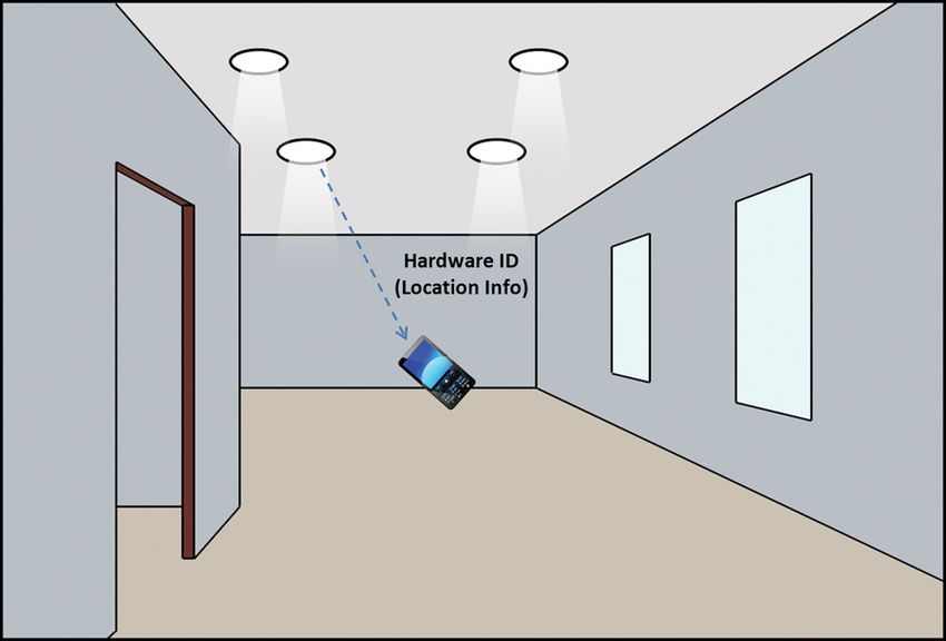
Zhang, Chowdhury, and Kavehrad: Asynchronous indoor positioning system based on visible light communications

                Fig. 14 Positioning error (in units of meter) distribution under indirect
                sunlight exposure assuming wrong positions of LED bulbs.                          Fig. 17 CDF curves of positioning error under direct and indirect sun-
                                                                                                  light exposure assuming wrong positions of LED bulbs.

                                                                                                  4 Conclusions
                                                                                                  In this article, an asynchronous indoor positioning system
                                                                                                  based on VLC technology is proposed. The use of BFSA
                                                                                                  protocol is addressed as a solution to the channel multiaccess
                                                                                                  problem. The feasibility of this protocol is then shown
                                                                                                  considering the realistic modulation bandwidth of a typical
                                                                                                  LED. After noise analysis, simulation results for indoor
                                                                                                  environments with both direct and indirect sunlight exposure
                                                                                                  were described. Results indicate that the proposed system
                                                                                                  is able to provide indoor positioning service with a precision
                                                                                                  of 95% within 17.25 cm assuming direct sunlight exposure,
                                                                                                  and a precision of 95% within 11.2 cm when indirect sun-
                                                                                                  light exposure is assumed, taking possible wrong positions
                                                                                                  of LED bulbs and orientation angle of the receiver into
                                                                                                  consideration.

                                                                                                  Acknowledgments
                                                                                                  This research in part was supported by a National Science
                Fig. 15 Histogram of positioning error assuming wrong positions of                Foundation award IIP-1169024, IUCRC on optical wireless
                LED bulbs (direct sunlight exposure).                                             applications.

                                                                                                  References
                                                                                                     1. C. Wang et al., “An implementation of positioning system in indoor
                                                                                                        environment based on active RFID,” in IEEE Joint Conf. on Pervasive
                                                                                                        Computing, pp. 71–76 (2009).
                                                                                                     2. J. Zhou et al., “Providing location services within a radio cellular
                                                                                                        network using ellipse propagation model,” in IEEE 19th Int. Conf.
                                                                                                        Advanced Information Networking and Applications, pp. 559–564
                                                                                                        (2005).
                                                                                                     3. Y. Liu and Y. Wang, “A novel positioning method for WLAN based on
                                                                                                        propagation modeling,” in 2010 IEEE Int. Conf. Progress in
                                                                                                        Informatics and Computing, pp. 397–401 (2010).
                                                                                                     4. L. Son and P. Orten, “Enhancing accuracy performance of Bluetooth
                                                                                                        positioning,” in 2007 IEEE Wireless Communications and Networking
                                                                                                        Conf., pp. 2726–2731 (2007).
                                                                                                     5. H. Liu et al., “Survey of wireless indoor positioning techniques and
                                                                                                        systems,” IEEE Trans. Syst., Man, Cybernet., Part C: Appl. Rev.
                                                                                                        37(6), 1067–1080 (2007).
                                                                                                     6. W. Zhang and M. Kavehrad, “A 2-D indoor localization system based
                                                                                                        on visible light LED,” in Proc. IEEE Photonics Society Summer
                                                                                                        Topical Conf.—Optical Wireless Systems Applications, pp. 80–81
                                                                                                        (2012).
                                                                                                     7. Z. Zhou, M. Kavehrad, and P. Deng, “Indoor positioning algorithm
                                                                                                        using light-emitting diode visible light communications,” Opt. Eng.
                                                                                                        51(8), 085009 (2012).
                                                                                                     8. K. Panta and J. Armstrong, “Indoor localisation using white LEDs,”
                                                                                                        Electron. Lett. 48(4), 228–230 (2012).
                                                                                                     9. S. Y. Jung, S. Hann, and C. S. Park, “TDOA-based optical wireless
                Fig. 16 Histogram of positioning error assuming wrong positions of                      indoor localization using LED ceiling lamps,” IEEE Trans.
                LED bulbs (indirect sunlight exposure).                                                 Consum. Electron. 57(4), 1592–1597 (2011).

                Optical Engineering                                                       045105-8                                                 April 2014   •   Vol. 53(4)

Downloaded From: https://www.spiedigitallibrary.org/journals/Optical-Engineering on 05 Nov 2021
Terms of Use: https://www.spiedigitallibrary.org/terms-of-use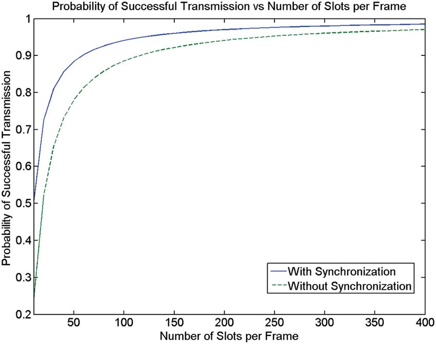
Zhang, Chowdhury, and Kavehrad: Asynchronous indoor positioning system based on visible light communications

                 10. T. Tanaka and S. Haruyama, “New position detection method using              Weizhi Zhang obtained his BS degree from the Department of
                     image sensor and visible light LEDs,” in IEEE Second Int. Conf.              Physics at South China University of Technology, Guangzhou,
                     Machine Vision. ICMV’09, pp. 150–153 (2009).                                 China, in 2009. He is now working toward his PhD degree in electrical
                 11. S. Hann et al., “White LED ceiling lights positioning systems for            engineering at the Pennsylvania State University. He is a researcher
                     optical wireless indoor applications,” in IEEE 36th European
                     Conference and Exhibition on Optical Communication (ECOC),                   at the Center on Optical Wireless Applications (COWA). His research
                     pp. 1–3, IEEE (2010).                                                        is currently focused on optical communication and related applica-
                 12. Y. U. Lee et al., “Hybrid positioning with lighting LEDs and Zigbee          tions, especially indoor optical positioning and free-space optics.
                     multihop wireless networks,” Proc. SPIE 8282, 82820L (2012).
                 13. Y. U. Lee and M. Kavehrad, “Two hybrid positioning system design             M. I. Sakib Chowdhury obtained his BSc degree in electrical and
                     techniques with lighting LEDs and ad-hoc wireless network,” IEEE             electronic engineering from Bangladesh University of Engineering
                     Trans. Consum. Electron. 58(4), 1176–1184 (2012).                            and Technology in 2007. He worked for 3 years in the telecommuni-
                 14. J. M. Kahn and J. R. Barry, “Wireless infrared communications,” Proc.        cations industry upon his graduation. He is currently a PhD student in
                     IEEE 85(2), 265–298 (1997).                                                  the EE Department at the Pennsylvania State University and
                 15. M. Bolic, D. Simplot-Ryl, and I. Stojmenovic, RFID Systems,
                     Research Trends and Challenges, Wiley, New York (2010).                      a researcher of Center on Optical Wireless Applications (COWA).
                 16. G. Archenhold, “Health and safety of artificial lighting,” Mondo Arc         His research interests include indoor optical wireless communications
                     63, 111–118 (2011).                                                          and radio frequency-based communications in next-generation
                 17. T. Komine and M. Nakagawa, “Fundamental analysis for visible-light           mobile networks.
                     communication system using LED lights,” IEEE Trans. Consum.
                     Electron. 50(1), 100–107 (2004).                                             Mohsen Kavehrad is with the Pennsylvania State University EE
                 18. A. J. Moreira, R. T. Valadas, and A. M. de Oliveira Duarte, “Optical         Department as Weiss Chair professor and director of the Center
                     interference produced by artificial light,” Wireless Networks 3(2),          for Information and Communications Technology Research. He
                     131–140 (1997).
                 19. R. G. Smith and S. D. Personick, “Receiver design for optical fiber          has published over 350 papers, book chapters, books, and key pat-
                     communication systems,” in Semiconductor Devices for Optical                 ents. His research interests are in the areas of wireless and optical
                     Communication, pp. 89–160, Springer, Berlin Heidelberg (1982).               communications networked systems. In January 2012, he became
                 20. A. P. Tang, J. M. Kahn, and K. P. Ho, “Wireless infrared communi-            a director of an NSF Industry/University Cooperative Research
                     cation links using multi-beam transmitters and imaging receivers,”           Center, jointly with Georgia Tech, called the Center on Optical
                     in IEEE Int. Conf. Communications. ICC 96, Conference Record,                Wireless Applications.
                     Converging Technologies for Tomorrow’s Applications, Vol. 1,
                     pp. 180–186 (1996).

                Optical Engineering                                                       045105-9                                              April 2014   •   Vol. 53(4)

Downloaded From: https://www.spiedigitallibrary.org/journals/Optical-Engineering on 05 Nov 2021
Terms of Use: https://www.spiedigitallibrary.org/terms-of-use
You can also read