Autonomous Driving Robot That Drives and Returns along a Planned Route in Underground Mines by Recognizing Road Signs
←
→
Page content transcription
If your browser does not render page correctly, please read the page content below
applied
              sciences
Article
Autonomous Driving Robot That Drives and Returns along a
Planned Route in Underground Mines by Recognizing
Road Signs
Heonmoo Kim and Yosoon Choi *

                                          Department of Energy Resources Engineering, Pukyong National University, Busan 48513, Korea;
                                          kimhunmu@gmail.com
                                          * Correspondence: energy@pknu.ac.kr; Tel.: +82-51-629-6562; Fax: +82-51-629-6553

                                          Abstract: In this study, an autonomous driving robot that drives and returns along a planned
                                          route in an underground mine tunnel was developed using a machine-vision-based road sign
                                          recognition algorithm. The robot was designed to recognize road signs at the intersection of a tunnel
                                          using a geometric matching algorithm of machine vision, and the autonomous driving mode was
                                          switched according to the shape of the road sign to drive the robot according to the planned route.
                                          The autonomous driving mode recognized the shape of the tunnel using the distance data from the
                                          LiDAR sensor; it was designed to drive while maintaining a fixed distance from the centerline or
                                          one wall of the tunnel. A machine-vision-based road sign recognition system and an autonomous
                                          driving robot for underground mines were used in a field experiment. The results reveal that all road
                                          signs were accurately recognized, and the average matching score was 979.14 out of 1000, confirming

                                   stable driving along the planned route.
Citation: Kim, H.; Choi, Y.
Autonomous Driving Robot That
                                          Keywords: smart mining; underground mine; road sign recognition; machine vision; autonomous driving
Drives and Returns along a Planned
Route in Underground Mines by
Recognizing Road Signs. Appl. Sci.
2021, 11, 10235. https://doi.org/         1. Introduction
10.3390/app112110235                            Autonomous driving technology enables vehicles to automatically drive to a desired
                                          point by recognizing and judging the driving environment. Recently, autonomous driving
Academic Editors: Paola Pellegrini        technology has been applied to mobile robots and is being used in fields such as manufac-
and Rocco Furferi
                                          turing [1], logistics [2], and national defense [3]. Many studies [4–12] have been conducted
                                          to implement high-level autonomous driving technology in these fields. For example, Datta
Received: 12 August 2021
                                          et al. [13] tested various tasks in a manufacturing environment using autonomous mobile
Accepted: 27 October 2021
                                          robots equipped with wheel encoders, cameras, light detection and ranging (LiDAR), and
Published: 1 November 2021
                                          robot arms. Wang and Du [14] developed an autonomous driving robot for logistics using
                                          an infrared sensor, encoder, global positioning system (GPS), ultrasonic sensor, navigation,
Publisher’s Note: MDPI stays neutral
                                          path planning, and information fusion functions. Park et al. [15] developed a military
with regard to jurisdictional claims in
                                          autonomous driving robot equipped with a laser scanner, GPS, and camera.
published maps and institutional affil-
iations.
                                                In the mining industry, several studies of autonomous driving technology have been
                                          conducted in underground mining environments using autonomous robots [16–26]. Baker
                                          et al. [27] developed “groundhog”, an autonomous driving robot that can be used even in
                                          underground mines having poor road conditions. The autonomous driving robot was able
                                          to recognize the surrounding environment through the fusion of multiple sensors, perform
Copyright: © 2021 by the authors.
                                          tasks such as tunnel mapping, and return to the starting point. Field driving tests were
Licensee MDPI, Basel, Switzerland.
                                          performed in an abandoned mine environment using the developed autonomous driving
This article is an open access article
                                          robot, and stable driving performance was confirmed. Bakambu [28] used an autonomous
distributed under the terms and
conditions of the Creative Commons
                                          robot to estimate real-time location in an underground mining environment, performed 2D
Attribution (CC BY) license (https://
                                          and 3D tunnel mapping work, and evaluated its accuracy.
creativecommons.org/licenses/by/                Recently, studies have been conducted on the use of autonomous robots with camera
4.0/).                                    sensors for underground mining [29,30]. Zhao et al. [31] developed an autonomous driving

Appl. Sci. 2021, 11, 10235. https://doi.org/10.3390/app112110235                                           https://www.mdpi.com/journal/applsci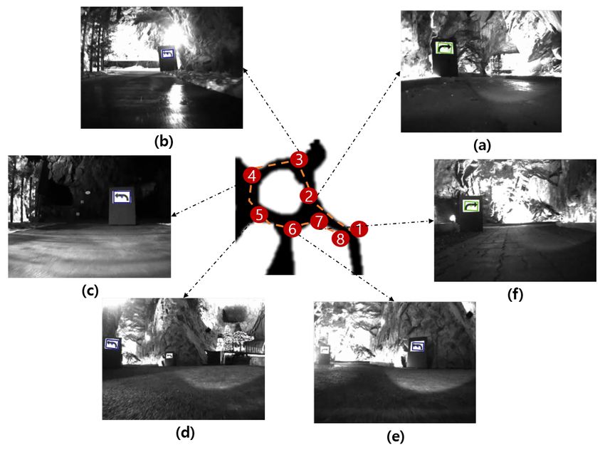
Appl. Sci. 2021, 11, 10235                                                                                          2 of 13

                             robot to perform initial exploration work in case of a human accident in an underground
                             coal mine. In addition to being capable of autonomous driving, the developed robot can
                             be remote controlled, and is equipped with a toxic gas detection sensor, camera sensor,
                             and long-distance wireless communication router; furthermore, the operator can check
                             the driving environment in real time using a camera. Jing et al. [32] performed 3D tunnel
                             mapping for an underground mine tunnel using mobile robots and a depth camera that
                             can recognize 3D views. Zeng et al. [33] developed a real-time localization system in an
                             underground mine using an autonomous driving loader for underground mining and a
                             camera sensor. The developed localization system was able to perform accurate localization
                             by integrating image processing technology and simultaneous localization and mapping.
                                   As aforementioned, most previous studies using autonomous robots in underground
                             mines involved autonomous driving along only certain straight paths in underground
                             mine tunnels. However, in a real underground mining environment, autonomous driving
                             in a straight tunnel section as well as path planning technology to drive, for example, in
                             a planned direction on a two-way road or returning after arriving at a turning point, are
                             required. In addition, in underground mines, the shape of the tunnel is frequently changed
                             by the blasting of the tunnel for mining minerals, making it difficult to effectively utilize
                             the route planning technology using the global map surveyed in advance. Therefore, to
                             improve the utilization of autonomous robots for underground mining, technologies for
                             efficiently recognizing road signs using a camera sensor-based vision system and driving
                             along a planned route in an underground mine without a global map should be developed.
                                   The purpose of this study was to realize the autonomous driving and returning of a
                             robot along a planned route in underground mine tunnels using a machine-vision-based
                             road sign recognition algorithm. While driving, the autonomous driving robot recognizes
                             the shape of the underground mine using a LiDAR sensor and drives along the centerline
                             of the road. After recognizing the road sign, it switches to the left or right wall-following
                             driving mode. In this paper, the system configuration of autonomous driving robots and
                             the road sign recognition algorithm are explained, and the results of field experiments in
                             underground mines are presented.

                             2. Materials and Methods
                             2.1. Autonomous Driving Robot
                                  Table 1 provides the details of the equipment of the autonomous driving robot system
                             developed in this study. Th autonomous driving robot consists of a controller, mobile
                             robot, and sensors. In this study, a laptop PC with a Windows 10 (Microsoft Corporation,
                             Redmond, WA, USA) operating system was used as the main controller, and an ERP-42
                             robot equipped with four-wheel drive and four-wheel steering was used as the mobile
                             robot. A vision camera, LiDAR sensor, inertial measurement unit (IMU) sensor, and wheel
                             encoder sensor were used to perform pose estimation, localization, and object detection.
                             The vision camera used was the Bumblebee XB3, a stereo camera, but only RGB images were
                             used because road signs had to be recognized. The IMU sensor fuses the magnetometer,
                             acceleration, and gyroscope sensor using a Kalman filter to output the 3-axis Euler angle
                             for the robot’s pose [26].
                                  Figure 1 shows the interior and exterior of the autonomous driving robot developed
                             in this study. A LiDAR sensor, webcam, and vision camera were installed in the front side
                             the robot. A LiDAR sensor was used to recognize the shape of the underground mine
                             tunnel, and the webcam was designed to transmit the webcam display to the remote laptop.
                             In addition, a vision camera was used to recognize road signs. A battery and converter
                             were placed to supply power to the robot and the sensors. A protective case was used to
                             safeguard the internal equipment from external physical shocks and water leakage.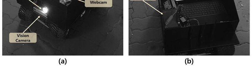
Appl. Sci. 2021, 11, 10235 3 of 13
Table 1. Specifications of sensors, controller, and driving platform used in this study.
Equipment Model Specification
Laptop PC Intel Core i7-9750H CPU 4.50 GHz (Intel, Santa Clara,
Main Controller Windows 10 (Microsoft Corporation, CA, UAS), 16 GB RAM, NVIDIA GeForce 1650 4GB
Redmond, WA, USA) (NVIDIA, Santa Clara, CA, USA)
Size: 650 mm (length) × 470 mm (width) × 158 mm
(height)
Weight: 8kg
Drive: 4 differential gears
Mobile Robot ERP-42 (Unmanned Solution, Seoul, Korea)
Max speed: 8 km/h
Max run time: 2.5 h
Battery: 14.8 V, 12 ah
Lighting intensity: 1050 lumen
Image: ICX445 (1280 × 960 max pixels)
3.75 µm square pixels
Vision Camera Bumblebee XB3 (Flir, Wilsonville, OR, USA)
Interface: IEEE-1394
Frame Rate: 16 FPS
Field of View: 270◦
Interface: TCP/IP
LiDAR LMS-111 (SICK, Waldkirch, Germany)
Operating Range: 0.5 m–20 m
Scanning frequency: 25 Hz/50 Hz
Error: Roll/Pitch ± 0.2◦ , Yaw ± 0.5◦
IMU EBIMU–9DOFV4 (E2BOX, Hanam, Korea)
Output Range: −180–+180◦
IG-32PGM 01TYPE (YOUNGJIN B&B, Seoul,
Appl. Sci. 2021,Wheel encoder
11, x FOR PEER REVIEW Korea)
Motor gear ratio: 13Encoder gear ratio: 61 4 of 14
Figure
Figure 1.
1. Autonomous
Autonomous driving
driving robot
robot and
and sensors
sensors used
used in
in this
this study:
study: (a)
(a) external
external view,
view, and
and (b)
(b) internal view.
internal view.
2.2. Machine
2.2. Machine Vision
Vision Algorithm
Algorithm
In this
In this study,
study, a machine vision algorithm was was used
used to
to recognize
recognize road
road signs
signs in
in under-
under-
ground mines. In the case of
ground mines. In the case of general general roads, an object recognition technology based on
artificial intelligence using a large amount of learning data should be used to recognize aa
artificial intelligence using a large amount of learning data should be used to recognize
wide variety
wide variety of
of road
road signs.
signs. In
In contrast,
contrast, in
in the
the case
case of
of underground
underground mines,
mines, it
it is
is sufficient
sufficient to
to
recognize only
recognize only the
the right
right and
and left
left road
road signs
signs at
at intersections because the
intersections because the driving
driving route
route is
is
limited to the excavated tunnel. Therefore, in this study, we used a geometric
limited to the excavated tunnel. Therefore, in this study, we used a geometric matching matching
algorithm, which
algorithm, which isis aa machine
machine vision
vision technology
technology thatthat uses
uses aa single
single image
image asas learning
learning data
data
to recognize road signs without the use of several computational
to recognize road signs without the use of several computational resources. resources.
Geometric matching is a technology that detects the boundary line of an object using
an edge detection algorithm, compares it with the shape of a template image, and matches
it. Geometric matching algorithms can be used efficiently when the distinction between
the object and the background is clear; however, the efficiency is low when the boundary
of the object is not clear or when matching only a part of the object. Geometry matching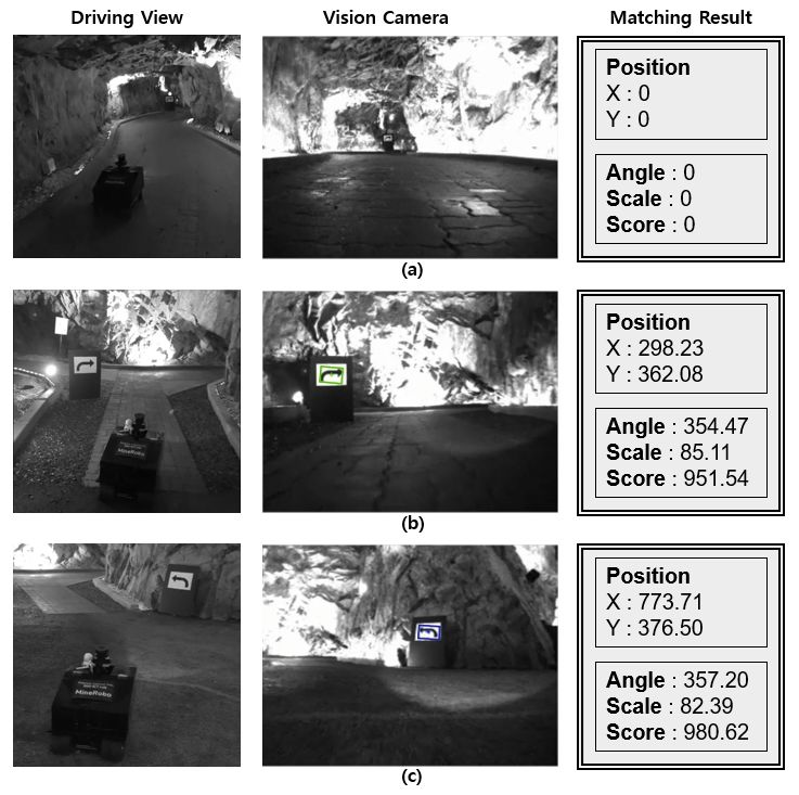
Appl. Sci. 2021, 11, 10235 4 of 13
Geometric matching is a technology that detects the boundary line of an object using
an edge detection algorithm, compares it with the shape of a template image, and matches
it. Geometric matching algorithms can be used efficiently when the distinction between the
object and the background is clear; however, the efficiency is low when the boundary of the
object is not clear or when matching only a part of the object. Geometry matching shows
high performance even in the presence of lighting changes, blurring, and noise. It can be
efficiently performed based on geometrical shape changes, such as the movement, rota-
tion, and scale change of an object on a screen. Geometric matching can be classified into
commonly used edge-based geometric matching techniques and feature-based geometric
matching techniques for matching circular, square, and linear template images. The geo-
metric matching algorithm consists of the following steps: learning (curve extraction and
feature extraction) and matching (feature correspondence matching, template model match-
ing, and match refinement). Figure 2 shows the template image and matching result
Appl. Sci. 2021, 11, x FOR PEER REVIEW of
5 of 14
geometric matching. At the top of the matching result image, the matching image number,
the center pixel coordinates of the matched image, and the matching score are displayed.
Matching result
Figure2.2.Matching
Figure result and template
template image
imageof
ofthe
thegeometric
geometricmatching
matchingalgorithm used
algorithm inin
used this study.
this
study.
This method employs normalized gray values and implements more accurate match-
ing when there isemploys
This method a dense normalized
texture. When the
gray size of
values theimplements
and template image more is K × L and
accurate the
match-
sizewhen
ing of thethere
targetisimage
a denseis M × N, the
texture. cross
When correlation
the size of theattemplate
(i, j) is calculated
image isusing
K × LEquation
and the
(1). of
size Figure 3 shows
the target the correlation
image is M × N, the between the template
cross correlation at image and the target
(i, j) is calculated image
using when
Equation
performing pattern matching [34].
(1). Figure 3 shows the correlation between the template image and the target image when
performing pattern matching [34].
−1 K−1
∑Lx= 0 ∑y=0 (w(x, y) − w)(f(x + i, y + j) − f(i, j))
C(i, j) = q (1)
(w(x, 2y) − L
∑xw)(f(x +1i, y + j) − f(i, j))
q
−1 K−1 −1 K− 2
∑xL= ∑
0 y=0 ( w ( x, y ) − w ) =0 ∑y=0 (f(x + i, y + j) − f(i, j))
C(i, j) =
(1)
where i = 0, 1, 2, . . . , M−1 and j(w(x,
= 0, 1,y)2,−....
w)The correlation is calculated
(f(x + i, y + j)through
− f(i, j))the C(i, j)
value at the highest point among the values up to N − 1.
where i = 0, 1, 2, …, M−1 and j = 0, 1, 2, .... The correlation is calculated through the C(i, j)
value at the highest point among the values up to N − 1.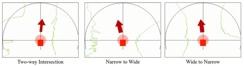
(w(x, y) − w)(f(x + i, y + j) − f(i, j))
                                        C(i, j) =
                                                                                                                                (1)
                                                                 (w(x, y) − w)                  (f(x + i, y + j) − f(i, j))

Appl. Sci. 2021, 11, 10235                                                                                                    5 of 13
                             where i = 0, 1, 2, …, M−1 and j = 0, 1, 2, .... The correlation is calculated through the C(i, j)
                             value at the highest point among the values up to N − 1.

                             Figure
                              Figure 3.
                                      3. Conceptual
                                         Conceptualdiagram
                                                     diagramof
                                                             ofcross
                                                                cross correlation
                                                                       correlation between
                                                                                   between template
                                                                                            template image
                                                                                                      image and
                                                                                                            and target
                                                                                                                 target image
                                                                                                                         image for
                                                                                                                               for
                             calculating
                              calculatingthe
                                          thepattern
                                              patternmatching
                                                     matchingscore.
                                                              score.

                                  The accuracy of the matching algorithm is calculated using Equation (2) [35]. In this
                             study, National Instruments Vision Development Module, Vision Acquisition Software,
                             Vision Builder for Automated Inspection, Vision Assistant, and LabVIEW were used to
                             implement each matching algorithm [36].

                                                                          Matched Pixels
                                                        Match Score =                        × 1000                              (2)
                                                                         Total Pixels in ROI
                                  The match score indicates the matching accuracy score. It is output as a number
                             between 0 and 1000, and the closer it is to 1000, the higher the accuracy. The region of
                             interest (ROI) represents the area where matching is performed; in this study, it represented
                             the entire area captured by the camera.

                             2.3. Autonomous Driving and Wall following Algorithm
                                   In this study, we controlled the steering of an autonomous driving robot through the
                             distance difference between the left and right shaft walls measured through the LiDAR
                             sensors and the road signs detected by the vision camera. The autonomous driving robot
                             captured the RGB image from the vision camera, converted it into a grayscale image, and
                             checked the presence of road signs in real time using the road sign recognition algorithm.
                             If the road sign was not detected, the distance to the left and right walls was measured using
                             an autonomous driving algorithm, and the robot drove along the centerline of the road [22].
                             If the road sign was detected, the distance to the sign was calculated by comparing the scale
                             of the sign on the screen with the size of the actual road sign. The road sign used in this
                             study was 40 cm wide and 30 cm long. The type of road sign was recognized when it was
                             measured to be closer than the threshold distance. The distance was measured in the left or
                             right direction according to the type of recognized sign, and the vehicle traveled along one
                             wall at a certain distance. In this study, considering the speed of the robot and the width of
                             the underground mine tunnel, the robot was designed to detect when the road sign was
                             less than 5 m away, and it drove approximately 2 m away from the wall. Figure 4 shows
                             the processing diagram of the road sign recognition and autonomous driving algorithms.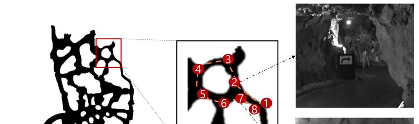
Appl.
Appl.Sci. 2021,11,
Sci.2021, 11,10235
x FOR PEER REVIEW 67of
of13
14
Figure 4. Process
Figure4. Process diagram
diagramof
ofroad
roadsign
signrecognition
recognitionand
andautonomous
autonomousdriving
drivingmode.
mode.
Equations
Equations (3)–(7)
(3)–(7) show
show the
the relationship
relationship between
between thethe distance
distance differences
differences (X(X input)
input)
measured from the LiDAR sensor and the steering angle (Y output) for
measured from the LiDAR sensor and the steering angle (Y output) for the autonomous the autonomous
driving
driving algorithm developedin
algorithm developed inthis
thisstudy.
study.Here,
Here, X represents
X represents the the value
value obtained
obtained by
by sub-
subtracting the distance to the left wall from the distance to the right wall, and
tracting the distance to the left wall from the distance to the right wall, and the Y value the Y value
represents
representsthethesteering
steeringvalue
valueofof
thetherobot. Max.
robot. Threshold
Max. Thresholdandand
Min. Threshold
Min. represent
Threshold the
represent
maximum and minimum threshold values at which the steering value changes,
the maximum and minimum threshold values at which the steering value changes, re- respectively.
That is, the Max.
spectively. That steering and steering
is, the Max. Min. steering meansteering
and Min. the maximum
mean thevalues that canvalues
maximum be moved
that
in the left and right directions, respectively; the Max. Threshold and Min. Threshold
can be moved in the left and right directions, respectively; the Max. Threshold and Min.
mean the threshold values at which the maximum and minimum steering values start,
Threshold mean the threshold values at which the maximum and minimum steering val-
respectively. Max. Steering and Min. Steering are the steering values for when the robot
ues start, respectively. Max. Steering and Min. Steering are the steering values for when
rotates, with a value between −100 and 100, with the left side representing (−) and the
the robot rotates, with a value between −100 and 100, with the left side representing (−)
right side representing (+). While the autonomous driving algorithm uses the distance
and the right side representing (+). While the autonomous driving algorithm uses the dis-
difference between the left and right walls, the wall-following algorithm controls steering
tance difference between the left and right walls, the wall-following algorithm controls
through the distance difference from one side wall [23]. That is, the autonomous driving
steering through the distance difference from one side wall [23]. That is, the autonomous
mode or the wall tracking mode is switched according to the direction indicated by the
driving mode or the wall tracking mode is switched according to the direction indicated
road mark, and the left and right steering are automatically controlled.
by the road mark, and the left and right steering are automatically controlled.
X < Max.Threshold,
X < Max. Threshold, Y = −Max.Steering
Y = −Max. Steering (3)
(3)
−Max.Threshold ≤Y −Max. SteeringValue(X
< Min.Threshold,
X= Y= − Min. Threshold)
−Max.SteeringValue (X−Min.Threshold)2
(4)
−Max. Threshold ≤ X < Min. Threshold, (Min.Threshold−Max.Treshold)2 (4)
(Min. Threshold − Max. Treshold)
− Min.Threshold ≤ X ≤ Min.Threshold, Y = 0 (5)
−Min. Threshold ≤ X ≤ Min. Threshold, Y = 0 2
(5)
Max.SteeringValue(X−Min.Threshold)
Min.Threshold < X ≤ Max.Threshold, Y = (6)
Max. SteeringValue(X − Min. Threshold)
(Max.Threshold −Min.Threshold)2
(6)
Min. Threshold < X ≤ Max. Threshold, Y =
(Max. Threshold Y−=
X > Max.Threshold, Min. Threshold)
Max.Steering (7)
X > Max. Threshold, Y = Max. Steering (7)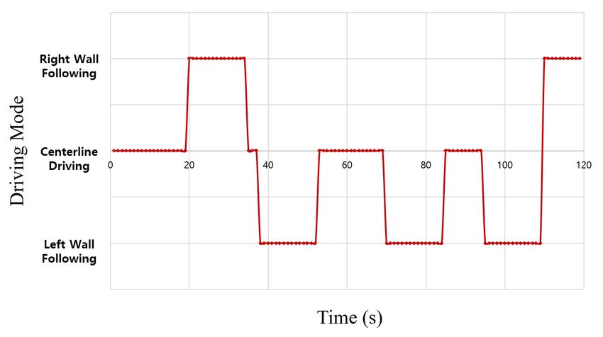
Appl.
Appl. Sci. 2021, 11,
Sci. 2021, 11, 10235
x FOR PEER REVIEW 78 of
of 13
14
2.4. Field Experiment
experimentswere
Field experiments wereconducted
conductedininananabandoned
abandoned underground
underground amethyst
amethyst mine
mine lo-
located
cated inin Korea
Korea (35◦ 320 43”
(35°32′43″ N,N, 129◦ 50 37”
129°5′37″ E). E). Specific
Specific areas
areas with
with a length
a length of approximately
of approximately 60
60 and
m m and a height
a height of of
2.52.5
mm amongallallthe
among theunderground
undergroundmine minetunnels
tunnelswere
were selected
selected as areas
for conducting the experiment, as shown in Figure 5. As shown in Figure 5, the the driving
driving
route was set by starting from Area 1 and returning to
returning AreaArea 8, and a total of six road signs
were
were placed
placed in
in areas
areas 2,
2, 3,
3, 4,
4, 5,
5, 6,
6, and
and 7.
7.
Conceptual diagram
Figure 5. Conceptual diagram of
of the (a) field experiment area and (b) road signs installed in the
the
underground mine.
In this study, the road road sign
sign installed
installed in
in the
the underground
underground mine
mine shaft
shaft was
was recognized
recognized
through the optimal matching algorithm selected from the indoor experiment, experiment, and the the
driving mode was switched to the wall-following algorithm algorithm in the left and right directions
according to
according to the
the type
type ofof road
road sign.
sign. In
In addition,
addition, when
when the
the wall-following
wall-following mode
mode continued
continued
for more
for more than
than 15 15 s,
s, it
it switched
switched to to the
the autonomous
autonomous driving
driving mode
mode that
that enables
enables driving
driving along
along
the centerline of the road. During the experiment, the driving path of the robot and the
the centerline of the road. During the experiment, the driving path of the robot and the
screen of
screen of the
thelaptop
laptopPC PCwere
wererecorded
recorded and
andanalyzed forfor
analyzed thethe
driving path,
driving driving
path, state,state,
driving and
recognition
and accuracy
recognition accuracyof road signs.
of road signs.
3. Results
3. Results
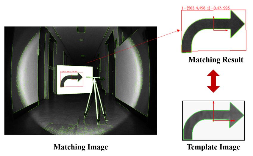
Figure 6 shows the autonomous driving robot recognizing road signs in the under-
Figure 6 shows the autonomous driving robot recognizing road signs in the under-
ground mine, driving straight and taking left and right turns; in addition, the matching
ground mine, driving straight and taking left and right turns; in addition, the matching
results of road signs are shown. In the straight section, we confirmed that the robot drove
results of road signs are shown. In the straight section, we confirmed that the robot drove
along the centerline of the tunnel, measuring both the distance to the wall in the left and
along the centerline of the tunnel, measuring both the distance to the wall in the left and
right directions without recognizing the road sign (Figure 6a). In the left and right turn
right directions without recognizing the road sign (Figure 6a). In the left and right turn
sections, we confirmed that the robot drove along the left and right walls by recognizing
sections, we confirmed that the robot drove along the left and right walls by recognizing
the road sign and switching the autonomous driving mode (Figure 6b,c). In the matching
the road sign and switching the autonomous driving mode (Figure 6b,c). In the matching
result in Figure 6, it can be seen that the x and y coordinates of the detected road sign
result in Figure 6, it can be seen that the x and y coordinates of the detected road sign were
were output. In addition, the rotation angle of the mark, the scale for the template image,
output.
and the In addition,
matching the rotation
score angle of the
were calculated. Themark, the scaledriving
autonomous for therobot
template image,
drove safelyand
in
the matching score were calculated. The autonomous driving robot drove
an underground mine tunnel of approximately 60 m for 128 s without a global map, safely in anand
un-
derground
we confirmedmine tunnel
that, of approximately
after recognizing 60 m itfor
road signs, 128 s without
returned a global
stably while map, and
following we
the left
confirmed that,
and right walls. after recognizing road signs, it returned stably while following the left
and right walls.Appl. Sci. 2021, 11, 10235 8 of 13
Appl. Sci. 2021, 11, x FOR PEER REVIEW 9 of 14
Figure 6. Figure 6. Field experimental
Field experimental scenes,scenes,
viewview of vision
of vision camera
camera andandmatching
matching results
results of
ofthe
theautonomous
autonomousdriving robotrobot
driving in (a) in (a) the
the straight section, (b) the right turn section, and (c) the left turn section.
straight section, (b) the right turn section, and (c) the left turn section.
Figure 7 illustrates the process of changing the autonomous driving mode when the
Figure 7 illustrates
autonomous robot drovethethrough
processthe
of tunnel.
changing Whilethedriving
autonomous
through driving mode when the
the underground
autonomous robot drove through the tunnel. While driving through
mine experiment area, it drove for 49 s in the centerline autonomous driving mode, the underground
25 s
mineinexperiment area, it drove
the right wall-following mode,for 4945s sininthe
and centerline
the left autonomous
wall-following mode. We driving
confirmed mode, 25 s
that the robot’s driving mode switched when six road signs were recognized;
in the right wall-following mode, and 45 s in the left wall-following mode. We confirmed furthermore,
when
that the the wall-following
robot’s driving mode mode lasted for
switched moresix
when than 15 s,signs
road it switched back to centerline
were recognized; furthermore,
tracking autonomous driving mode.
when the wall-following mode lasted for more than 15 s, it switched back to centerline
Appl. Sci. 2021, 11, x FOR PEER REVIEW 10 of 14
tracking autonomous driving mode.
Figure
Figure7.7.Graph
Graphshowing thethe
showing change in in
change autonomous driving
autonomous andand
driving wall-following mode
wall-following in the
mode infield
the field experiment.
experiment.
Figure 8 presents the data of the LiDAR sensor obtained from three road types (two-
way intersection, narrow-to-wide section, and wide-to-narrow section) and the robot’s
driving direction. At the two-way intersection, after recognizing the road sign in the right
direction, the robot drove along the right side at a constant distance. In the narrow-to-
wide section where the width of the road widened rapidly, after recognizing the road
signs in the left direction, the robot drove along the left side. In addition, in the wide-to-Appl. Sci. 2021, 11, 10235 9 of 13
Figure 7. Graph showing the change in autonomous driving and wall-following mode in the field
experiment.
Figure 8 presents the 8data
Figure of thethe
presents LiDAR
data sensor obtained
of the LiDAR fromobtained
sensor three road types
from (two-
three road types (two-
way intersection,
way narrow-to-wide section, and wide-to-narrow
intersection, narrow-to-wide section) and the
section, and wide-to-narrow robot’s
section) and the robot’s
driving direction. At the
driving two-way
direction. Atintersection,
the two-wayafter recognizing
intersection, afterthe road sign in
recognizing thethe
roadright
sign in the right
direction, the direction,
robot drovethe along the right
robot drove alongside
theatright
a constant
side at adistance.
constant In the narrow-to-
distance. In the narrow-to-wide
wide section where
sectionthe width
where theof the road
width of thewidened rapidly,
road widened after recognizing
rapidly, the road
after recognizing the road signs in
signs in the left
thedirection, the robot
left direction, drovedrove
the robot along along
the left
theside.
left In addition,
side. in the in
In addition, wide-to-
the wide-to-narrow
narrow section,section, after recognizing
after recognizing thein
the sign sign
thein the
left left direction,
direction, it wasitpossible
was possible
for theforrobot
the robot to safely
to safely enterenter the narrow
the narrow path path without
without colliding
colliding with with the right
the right wall.wall.
Figure
Figure 8. Tunnel 8. Tunnel
shape shape
obtained fromobtained from LiDAR
LiDAR sensor sensor
in two-way in two-waynarrow-to-wide,
intersection, intersection, narrow-to-wide, and sections.
and wide-to-narrow
wide-to-narrow sections.
Figure 9 shows the results of recognizing road signs when the robot was driving in an
underground
Figure 9 shows mine.ofThe
the results autonomous
recognizing roaddriving robot recognized
signs when the robot was all road signsinat a total of six
driving
an underground points
mine.andThecorrectly classified
autonomous the road
driving robotsigns in the leftall
recognized and right
road directions.
signs at a totalIn Figure 9, two
of six points and road signs were
correctly captured
classified thetogether.
road signs However,
in the lefttheand
road signs
right recognition
directions. In system
Figure calculated the
9, two road signs distance
were bycaptured
comparing the size of
together. the matched
However, the image with the
road signs template image
recognition system and recognized
Appl. Sci. 2021, 11, x FOR PEER REVIEW 11 of 14
the relatively close road marker first. In addition,
calculated the distance by comparing the size of the matched image with the template we confirmed that the autonomous robot
sequentially recognized the road signs in the back.
image and recognized the relatively close road marker first. In addition, we confirmed The matching score for a total of six points
that the autonomous was calculated
robot
Scale as 979.14
92.51 points
(%)sequentially 81.11on average,
recognized the road
117.90 thesigns
scale
94.13inwas
the 80–120%,
82.39 The and
back. 85.11the rotation was
match-
◦ (Table 2).
ing score for ameasuredtotal Rotation (°) ±10
of sixtopoints
be 354.52
was 3.44 as 979.14
calculated 0.41 points 354.00
on average, 357.20
the scale354.47
was
80–120%, and the rotation was measured to be ±10° (Table 2).
Table 2. Field experimental results of autonomous driving robot for recognizing the road signs in
the underground mine.
Item Site 2 Site 3 Site 4 Site 5 Site 6 Site 7
Score 985.08 974.02 984.66 998.94 980.62 951.54
Direction Right Left Left Left Left Right
Figure 9. ViewFigure
of 9.recognizing
View of recognizing road signs
road signs in the in experimental
the experimentalarea
area using
usingvision
visionsystem developed
system in this study.
developed in this(a)study.
Site 2. (a) Site 2. (b)
(b) Site 3. (c) Site 4. (d) Site 5. (e) Site 6. (f) Site 7.
Site 3. (c) Site 4. (d) Site 5. (e) Site 6. (f) Site 7.
4. Discussion
4.1. Applications and Expected Effect
An autonomous driving robot was employed in this study for underground mining
using the developed road sign recognition algorithm; the robot not only drove in a straight
tunnel, but also selected a path to drive at the intersection by recognizing the road signsAppl. Sci. 2021, 11, 10235 10 of 13
Table 2. Field experimental results of autonomous driving robot for recognizing the road signs in the
underground mine.
Item Site 2 Site 3 Site 4 Site 5 Site 6 Site 7
Score 985.08 974.02 984.66 998.94 980.62 951.54
Direction Right Left Left Left Left Right
Scale (%) 92.51 81.11 117.90 94.13 82.39 85.11
Rotation (◦ ) 354.52 3.44 0.41 354.00 357.20 354.47
4. Discussion
4.1. Applications and Expected Effect
An autonomous driving robot was employed in this study for underground mining
using the developed road sign recognition algorithm; the robot not only drove in a straight
tunnel, but also selected a path to drive at the intersection by recognizing the road signs
without a global map. It was feasible to perform multipoint path planning to return to the
tunnel entrance. In addition, if path-following technology can be used to drive and return
to a desired point in an area that is difficult for humans to access and where the driving
route changes frequently, such as in underground mines, the utilization of autonomous
robots will be useful in fields such as safe exploration and tunnel surveying.
Even if there is not enough learning image data for road signs due to the environmental
characteristics of underground mines, if an image matching algorithm that applies only a
single image as training data is used, road signs can be recognized efficiently. In addition,
a stable recognition performance can be maintained if the geometric matching algorithm
most suitable for an underground mining environment is used.
4.2. Limitations and Future Work
• Artificial intelligence object recognition: The shape of the entire tunnel changes fre-
quently because of the ongoing excavation work in underground mines, and accord-
ingly, the movement paths of vehicles and workers also change frequently. Hence,
road signs at actual underground mine sites are often temporarily marked on the
wall. Therefore, the utilization of the road sign recognition system can be expected
to further expand if the image of each temporary marker is stored as data and object
recognition technology that uses a large number of learning images, such as machine
learning and deep learning, is used. In addition, the recognition of static objects, such
as workers or transport equipment in the tunnel, as well as stationary road signs, may
be performed.
• Sensor: Because there are no lanes in underground mines, the drivable area is un-
clear, and because the shape of the tunnel wall is irregular, collisions may occur in
unpredictable areas. Therefore, it is suggested to use not only the 2D LiDAR sensor
or vision camera in this study, but also a 3D LiDAR that can widely recognize the
rear, side, and upper part of the tunnel. In addition, because the intensity of lighting
is different for each underground mining site, and the accuracy of matching may be
reduced if the lighting is too strong, an illuminance sensor that can recognize the
illuminance intensity of the surroundings and reflect it in the lighting system should
be additionally utilized.
• Specificity of the underground mining site: The underground mining site has various
sections such as a U-turn area, a three-pronged road, and an area where minerals are
loaded, in addition to straight, left, and right turns. Therefore, to consider these envi-
ronmental characteristics and changes, additional research on autonomous driving
algorithms for driving in complex routes should be conducted.
• Road sign visibility: In an underground mine environment, dust is frequently gener-
ated by blasting, and puddles and mud can be caused by stagnant water on the edge
of the road. The visibility of the road sign may be limited by these factors, and the
robot may not accurately recognize the road sign. Therefore, for a robot to drive along
a planned route, elements (dust, mud) that hinder visibility must be periodically re-Appl. Sci. 2021, 11, 10235 11 of 13
moved. In addition, in mines with large shafts, the minimum size to clearly recognize
road signs should be considered when driving along the centerline of the road, and
the installation location of road signs should be selected so as not to interfere with the
robot’s driving route [37].
5. Conclusions
In this study, an autonomous driving robot for underground mines and a road sign
recognition system using a machine-vision-based geometric matching algorithm were
developed. The developed system was designed to recognize road signs using a vision
camera and switch the autonomous driving mode for returning to the planned route while
the robot was driving through an underground mine. A field experiment conducted in an
underground mine demonstrated a matching score of 979.14 out of 1000. We confirmed
that the road signs were accurately recognized at all points, and the robot was driven stably
according to the wall tracking algorithm.
In the previous studies for developing autonomous robots utilized in underground
mines [22–26], the robots were forced to drive along a simple one-way route. However,
this study demonstrated that autonomous robots can drive complex multipoint routes
in underground mines while recognizing the road signs using a machine-vision-based
algorithm. Therefore, it became possible for autonomous robots to perform missions such
as environmental monitoring, 3D tunnel mapping, and accident detection as they navigate
complex routes in underground mines. Nevertheless, this study has a limitation in that
the driving experiment was conducted on flat and smooth road surfaces. In the future,
driving experiments and performance evaluation on rough and unpaved road surfaces
should be conducted.
Underground mines present environmental challenges in the application of autonomous
driving technology because GPS cannot be used and there are no lanes in such environments.
In particular, there is a limitation in that it is difficult to recognize road signs, workers, and
transport equipment because of insufficient light. Therefore, to increase the utilization of
autonomous driving technology in underground mining environments, it is very important
to develop and utilize a vision system that can recognize a wide range of environments. The
results of this study are expected to be useful reference materials for autonomous driving
technology to be used in underground mines in the future.
Author Contributions: Conceptualization, Y.C.; data curation, Y.C.; funding acquisition, Y.C.; in-
vestigation, H.K. and Y.C.; methodology, H.K. and Y.C.; project administration, Y.C.; resources,
Y.C.; software, Y.C.; supervision, Y.C.; validation, H.K.; visualization, H.K.; writing—original draft,
H.K.; writing—review and editing, Y.C. All authors have read and agreed to the published version
of the manuscript.
Funding: This work was supported by a National Research Foundation of Korea (NRF) grant funded
by the Korean government (MSIT) (2021R1A2C1011216).
Institutional Review Board Statement: Not applicable.
Informed Consent Statement: Not applicable.
Data Availability Statement: Data sharing not applicable.
Conflicts of Interest: The authors declare no conflict of interest.
References
1. Bavelos, A.C.; Kousi, N.; Gkournelos, C.; Lotsaris, K.; Aivaliotis, S.; Michalos, G.; Makris, S. Enabling Flexibility in Manufacturing
by Integrating Shopfloor and Process Perception for Mobile Robot Workers. Appl. Sci. 2021, 11, 3985. [CrossRef]
2. Kassai, E.T.; Azmat, M.; Kummer, S. Scope of Using Autonomous Trucks and Lorries for Parcel Deliveries in Urban Settings.
Logistics 2020, 4, 17. [CrossRef]
3. Reis, J.; Cohen, Y.; Melão, N.; Costa, J.; Jorge, D. High-Tech Defense Industries: Developing Autonomous Intelligent Systems.
Appl. Sci. 2021, 11, 4920. [CrossRef]Appl. Sci. 2021, 11, 10235 12 of 13
4. Fox, D.; Burgard, W.; Thrun, S. The dynamic window approach to collision avoidance. IEEE Robot. Autom. Mag. 1997, 4, 23–33.
[CrossRef]
5. Adams, M.; Zhang, S.; Xie, L. Particle filter based outdoor robot localization using natural features extracted from laser scanners.
In Proceedings of the IEEE International Conference on Robotics and Automation (ICRA ’04), New Orleans, LA, USA, 26 April–1
May 2004; Volume 2, pp. 1493–1498.
6. Thrun, S.; Burgard, W.; Fox, D. Probabilistic Robotics; MIT Press: Cambridge, MA, USA, 2005.
7. Moreno, L.; Armingol, J.M.; Garrido, S.; De La Escalera, A.; Salichs, M.A. A genetic algorithm for mobile robot localization using
ultrasonic sensors. J. Intell. Robot. Syst. Theory Appl. 2002, 34, 135–154. [CrossRef]
8. Liu, C.; Zhou, C.; Cao, W.; Li, F.; Jia, P. A Novel Design and Implementation of Autonomous Robotic Car Based on ROS in Indoor
Scenario. Robotics 2020, 9, 19. [CrossRef]
9. Boston Dynamics. Available online: https://www.bostondynamics.com/ (accessed on 5 July 2021).
10. DAIMLER’S PROMETHEUS Project. Available online: https://media.daimler.com/marsMediaSite/en/instance/ko/The-
PROMETHEUS-project-launched-in-1986-Pioneering-autonomous-driving.xhtml?oid=13744534 (accessed on 5 July 2021).
11. Masood, K.; Dauptain, X.; Zoppi, M.; Molfino, R. Hydraulic Pressure-Flow Rate Control of a Pallet Handling Robot for an
Autonomous Freight Delivery Vehicle. Electronics 2020, 9, 1370. [CrossRef]
12. Mercorelli, P. Using Fuzzy PD Controllers for Soft Motions in a Car-like Robot. Adv. Sci. Technol. Eng. Syst. J. 2018, 3, 380–390.
[CrossRef]
13. Datta, S.; Ray, R.; Banerji, D. Development of autonomous mobile robot with manipulator for manufacturing environment. Int. J.
Adv. Manuf. Technol. 2008, 38, 536–542. [CrossRef]
14. Wang, C.; Du, D. Research on logistics autonomous mobile robot system. In Proceedings of the 2016 IEEE International Conference
on Mechatronics and Automation, Harbin, China, 7–10 August 2016.
15. Park, Y.; Jee, T.; Kang, S.; Ryu, C.; Ko, J. Implementation of Autonomous Navigation based on the Open Architecture. J. Inst.
Electron. Eng. Korea 2007, 44, 34–38.
16. Miller, I.D.; Fernando, C.; Anthony, C.; Shivakumar, S.S.; Lee, E.S.; Jarin-Lipschitz, L.; Akhilesh, B.; Rodrigues, N.; Zhou, A.;
Cohen, A.; et al. Mine Tunnel Exploration Using Multiple Quadrupedal Robots. IEEE Rob. Autom. Lett. 2020, 5, 2840–2847.
[CrossRef]
17. Berglund, T.; Brodnik, A.; Jonsson, H.; Staffanson, M.; Söderkvist, I. Planning Smooth and Obstacle-Avoiding B-Spline Paths for
Autonomous Mining Vehicles. IEEE Trans. Autom. Sci. Eng. 2010, 7, 167–172. [CrossRef]
18. Bakambu, J.N.; Polotski, V. Autonomous system for navigation and surveying in underground mines. J. Field Rob. 2007, 24,
829–847. [CrossRef]
19. Shaffer, G.K.; Stentz, A.; Whittaker, W.L.; Fitzpatrick, K.W. Position Estimator for Underground Mine Equipment. IEEE Trans. Ind.
Appl. 1992, 28, 1131–1140. [CrossRef]
20. MobileTronics’s VirtuRail. Available online: https://innovation.strabag.com/en/project/virturail-with-an-autonomous-train-
into-the-heart-of-the-tunnel/ (accessed on 5 July 2021).
21. Günther, F.; Mischo, H.; Lösch, R.; Grehl, S.; Güth, F. Increased safety in deep mining with iot and autonomous robots.
In Proceedings of the 39th International Symposium ‘Application of Computers and Operations Research in the MIneral
Industry’(APCOM 2019), Wroclaw, Poland, 4–6 June 2019; Mueller, C., Assibey-Bonsu, W., Baafi, E., Dauber, C., Doran, C.,
Jaszczuk, M.J., Nagovitsyn, O., Eds.; CRC Press: London, UK, 2019; pp. 101–105.
22. Kim, H.; Choi, Y. Development of a LiDAR Sensor-based Small Autonomous Driving Robot for Underground Mines and Indoor
Driving Experiments. J. Korean Soc. Miner. Energy Resour. Eng. 2019, 56, 407–415. [CrossRef]
23. Kim, H.; Choi, Y. Field Experiment of a LiDAR Sensor-based Small Autonomous Driving Robot in an Underground Mine. Tunn.
Undergr. Space 2020, 30, 76–86. [CrossRef]
24. Kim, H.; Choi, Y. Comparison of Three Location Estimation Methods of an Autonomous Driving Robot for Underground Mines.
Appl. Sci. 2020, 10, 4831. [CrossRef]
25. Kim, H.; Choi, Y. Self-driving algorithm and location estimation method for small environmental monitoring robot in underground
mines. Comput. Model. Eng. Sci. 2021, 127, 943–964. [CrossRef]
26. Kim, H.; Choi, Y. Location estimation of autonomous driving robot and 3D tunnel mapping in underground mines using pattern
matched LiDAR sequential images. Int. J. Min. Sci. 2021, 31, 779–788. [CrossRef]
27. Baker, C.; Morris, A.; Ferguson, D.; Thayer, S.; Whittaker, C.; Omohundro, Z.; Reverte, C.; Whittaker, W.; Thrun, S. A Campaign in
Autonomous Mine Mapping. In Proceedings of the IEEE International Conference on Robotics and Automation (ICRA ’04), New
Orleans, LA, USA, 26 April–1 May 2004; IEEE: New York, NY, USA, 2004.
28. Bakambu, J.N. Integrated autonomous system for exploration and navigation in underground mines. In Proceedings of the IEEE
International Conference on Intelligent Robots and Systems, Beijing, China, 9–15 October 2006.
29. Szrek, J.; Zimroz, R.; Wodecki, J.; Michalak, A.; Góralczyk, M.; Worsa-Kozak, M. Application of the Infrared Thermography and
Unmanned Ground Vehicle for Rescue Action Support in Underground Mine—The AMICOS Project. Remote Sens. 2021, 13, 69.
[CrossRef]
30. Szrek, J.; Wodecki, J.; Błażej, R.; Zimroz, R. An Inspection Robot for Belt Conveyor Maintenance in Underground Mine—Infrared
Thermography for Overheated Idlers Detection. Appl. Sci. 2020, 10, 4984. [CrossRef]Appl. Sci. 2021, 11, 10235 13 of 13
31. Zhao, J.; Gao, J.; Zhao, F.; Liu, Y. A Search and Rescue Robot System for Remotely Sensing the Underground Coal Mine
Environment. Sensors 2017, 17, 2426. [CrossRef] [PubMed]
32. Jing, N.; Ma, X.; Guo, W.; Wang, M. 3D Reconstruction of Underground Tunnel Using Depth-camera-based Inspection Robot.
Sensors Mater. 2019, 31, 2719–2734. [CrossRef]
33. Zeng, F.; Jacobson, A.; Smith, D.; Boswell, N.; Peynot, T.; Milford, M. TIMTAM: Tunnel-Image Texturally Accorded Mosaic for
Location Refinement of Underground Vehicles with a Single Camera. IEEE Robot. Autom. Lett. 2019, 4, 4362–4369. [CrossRef]
34. IMAQ Vision Concept Manual. Available online: https://www.ni.com/pdf/manuals/322916a.pdf (accessed on 5 July 2021).
35. Sharma, G.; Sood, S.; Singh Gaba, G.; Gupta, N. Image Recognition System using Geometric Matching and Contour Detection.
Int. J. Comput. Appl. 2012, 51, 48–53. [CrossRef]
36. National Instruments. Available online: https://www.ni.com/ (accessed on 5 July 2021).
37. Civera, M.; Zanotti Fragonara, L.; Surace, C. Using Video Processing for the Full-Field Identification of Backbone Curves in Case
of Large Vibrations. Sensors 2019, 19, 2345. [CrossRef] [PubMed]You can also read