CLARIFICATION GUIDE OF THE UCI TECHNICAL REGULATION
←
→
Page content transcription
If your browser does not render page correctly, please read the page content below

CLARIFICATION GUIDE
                OF THE UCI TECHNICAL REGULATION
01.01.2023 version
As the summit organization of world cycle sport, the International Cycling Union (UCI) is the
guarantor of the proper application of ethical and sporting regulations.
The UCI Regulations assert the primacy of man over machine. Observance of the regulations
by all parties involved facilitates sporting fairness and safety during competition.
This document does not replace Articles 1.3.001 to 1.3.034 of the UCI Regulations, but
rather complements them and illustrates the technical rules defined therein. The objective
of this document is to offer a definitive interpretation in order to facilitate understanding
and application of the Regulations by international commissaires, teams and manufacturers.
This practical guide applies to equipment used in road, track and cyclo-cross events. Each
discipline has its own technical characteristics and each may have variants depending on the
type of event.
The UCI Equipment Unit may be contacted by anyone seeking information on the technical
regulations. The technical regulations can be consulted on the UCI website under the "Rules"
heading. Further details on the approval procedures for frames, forks and wheels are also
available on the UCI website under the "Equipment" heading.
DEFINITIONS
    B
    •   BAR END PLUGS – a handlebar accessory that exclusively covers open ends of the
        handlebar / extensions / base bar.
    •   BASE BAR – a steering assembly with a grip position allowing for an aerodynamic
        posture.
    •   BESPOKE EQUIPMENT – any product that belongs to a brand and a model range and
        offers customisation features around the adaptation of the equipment.
    •   BICYCLE - a vehicle with two wheels of equal diameter. The front wheel shall be
        steerable; the rear wheel shall be driven through a system comprising pedals and a
        chain. Exceptions to this rule may exist for certain cycling disciplines, in which case
        specific rules are provided for in the respective discipline.
    •   BOTTLE CAGE – an add-on accessory used to affix a water bottle to a bicycle.
    E
    •   EQUIPMENT – any product a rider will use in the UCI sanctioned event including but
        not limited to clothing, safety equipment and bicycles.
    F
        FOREARM SUPPORT – a component of the fixed additional time trial extension
        handlebar that provides an additional point of support.

                                                                                             1
CLARIFICATION GUIDE OF THE UCI TECHNICAL REGULATION

  H
  •   HANDLEBAR COCKPIT – a combination of the handlebars or the base bar with the
      fixed additional time trial extension handlebar, stem plus any accessories (controls,
      levers, etc. and all their mounting accessories).
  •   FIXED ADDITIONAL TIME TRIAL EXTENSION HANDLEBAR – a steering assembly
      secured to the handlebar or the base bar to improve the rider’s aerodynamic
      posture.
  •   HANDLEBAR GRIP – an accessory designed to provide padding and vibration
      damping to ensure a proper grip between the hands and the handlebars.
  •   CYCLING COMPUTER MOUNT – an accessory that is designed solely for the secure
      installation of a cycling computer.
  M
  •   MAXIMUM / MINIMUM DIMENSION OF THE CROSS SECTION - the largest and
      smallest dimensions of tube sections respectively, i.e. the maximum and minimum
      dimensions authorised in any direction.
  R
  •   RECTANGULAR BOX: The sides of the box are named as follows:

  •   REFERENCE PLANE - a nominally horizontal plane.
  S
  •   STEM - a component on a bicycle that connects the handlebars to the steerer tube
      of the bicycle fork.
  T
  •   TRADITIONAL HANDLEBARS (commonly referred to as a Drop Handlebars) - a
      steering assembly with multiple grip positions allowing for an aerodynamic posture.
      The handles of the traditional handlebars are bent below the rest of the bar.

                                                                                         2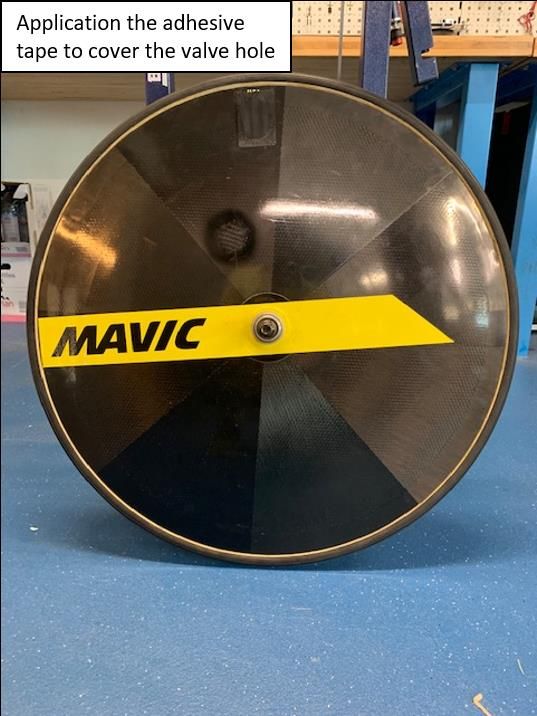
CLARIFICATION GUIDE OF THE UCI TECHNICAL REGULATION

Section 1 : general provisions
§ 1 Principles

ARTICLE 1.3.001

“Each licence holder shall ensure that his equipment (bicycle with accessories and other
devices fitted, headgear, clothing, etc.) does not, by virtue of its quality, materials or design,
constitute any danger to himself or to others.

The licence holder is responsible for his or her equipment and for ensuring its compliance
with the regulations. The licence holder must thus have knowledge of the technical
regulations to be able to apply them to the bicycle, accessories and clothing. The objective
of the approval procedures put in place by the UCI is to assist licence holders in this task.
The bicycle must be designed and constructed to the highest professional standards in
accordance with official quality and safety standards in a manner that respects the UCI's
technical regulations, allowing the rider to adopt, without difficulty or risk, the required
positions (support points, withdrawn saddle position, hands on the handlebars, position of
handlebar extensions, etc.).

ARTICLE 1.3.001 BIS

“Each licence holder shall ensure that the equipment he uses on the occasion of road, track
or cyclo-cross events shall be approved by the UCI according to the specifications of the
Approval Protocols in force and available on the UCI Website.”
The UCI put at disposal on the UCI website the list of homologated Road, Time-Trial, Cyclo-
cross, Track framesets (frame, fork, seat post and the frame components between the head
tube and the handlebar stem) as well as the Cyclo-cross and road wheels under the
"Equipment" heading. For any item of equipment that is subject to an approval procedure to
be used in competition, it must be approved in advance by the UCI with details published on
the website. The other material items don’t need to be homologated but must respect
article 1.3.006 obligations.

ARTICLE 1.3.002

“The UCI shall not be liable for any consequences deriving from the choice of the equipment
used by licence holders, nor for any defects it may have or its non-compliance. Equipment
used must meet all relevant ISO quality and safety requirements for bicycles (as referenced
for illustration purposes in the Clarification Guide published on the UCI website) as well as
any other standards applicable in the country of the event.”

“The licence-holder shall use the equipment which is certified and compliant with quality and
safety standards as provided by the manufacturer, without any modification whatsoever. The
licence-holder shall be entirely and exclusively liable for any modification made to the
equipment, in particular in the event of an incident, and may be subject to disciplinary
sanctions in accordance with the UCI Regulations.”

                                                                                                3
CLARIFICATION GUIDE OF THE UCI TECHNICAL REGULATION

Updated on 01.01.19

It is essential that the equipment used in competition meets the prevailing quality and safety
standards for bicycles. Mechanics and riders should also be aware of the ISO 4210 Standard
on safety that applies to cycling equipment. They should refer to this Standard before
modifying or adjusting any bicycle component. From 2019, all the framesets submitted to
the UCI for approval will have to join a certification confirming the compliance with the ISO
4210 security norm. The certification template is available in the section « Equipment » of
the UCI website.

Modifying equipment used in competition in relation to products supplied by the
manufacturer is prohibited for obvious safety reasons. Whether it is a matter of modifying
the length of the saddle, adapting approved wheels, filing off fork drop-out safety lugs or
meeting the 3:1 rule by adding tape to handlebars. No modification of equipment that is not
conducted by the manufacturer is authorized by the UCI without prior approval.

Figure 1: Examples of the prohibited modification of equipment (addition of tape, filing off
fork drop-out safety lugs)

Figure 2: Example of the prohibited modification of equipment (the carbon cover added to
the chainring
The addition of handlebar tape to improve a rider's grip and any addition of adhesive tape to
maintain, avoid abrasion, provide visual continuity or any other function is authorized in
condition when it does not constitute an excrescence or enlarges the general shape of
equipment.

                                                                                               4
CLARIFICATION GUIDE OF THE UCI TECHNICAL REGULATION

Figure 3: Example of application the adhesive tape on the Time Trial disc wheel

Figure 4: Illustration of the addition of the adhesive tape to cover bolts access

ARTICLE 1.3.003

“In no event shall the fact that a rider has been able to take part in the competition give rise
to liability on the part of the UCI; checks on equipment that may be carried out by the
commissaires or by an agent or a body of the UCI being limited to compliance with purely
sporting and technical requirements. Where required, checks on equipment and material
may be carried out, before, during or after the race, at the request of the president of the
commissaires’ panel, or that of an agent or body of the UCI.
For that purpose, the commissaire and the UCI can seize equipment for a subsequent check,
if necessary before, during or after the race, irrespective of whether the equipment was used
during the competition.

If the seized equipment is found not to comply with the requirements of the UCI Regulations,
the UCI may retain such item of equipment until the conclusion of any related disciplinary
proceedings.”

                                                                                              5
CLARIFICATION GUIDE OF THE UCI TECHNICAL REGULATION

ARTICLE 1.3.003 BIS

“Evading, refusing or failing to allow or enable a commissaire or other competent body to
conduct an equipment check shall be sanctioned as follows:
Rider or other team member: suspension of between one month and one year and/or a fine
of between CHF 1’000.- and CHF 100’000.-
Team: suspension of between one and six months and/or a fine between CHF 5’000 and CHF
100’000”

§ 2 Technical innovations

ARTICLE 1.3.004

“Except in mountain bike racing, no technical innovation regarding anything used, worn or
carried by any rider or license holder during a competition (bicycles, equipment mounted on
them, accessories, helmets, clothing, means of communication telemetry, device, sensors,
etc.) may be used until approved by the UCI. Requests for approval shall be submitted to the
UCI, accompanied by all necessary documentation.
All associated examination costs are to be paid by the applicant and are determined by the
UCI Management Committee according to the complexity of the submitted technical
innovation.
The UCI will study the application of the technical innovation from a sporting and technical
point of view and respond within 6 months from the date of submission of a complete file,
including the application, all relevant exhibits and any additional documents requested by
the UCI. The innovation comes into force as from the acceptance date.
There is no technical innovation in the sense of the present article if the innovation entirely
falls within the specifications foreseen in the regulations.”

Technical innovations must be submitted to the UCI in advance and approved by the
Equipment Commission before they can be used in competition.
A technical innovation is defined as a new system, device or item of equipment that allows
an improvement of a rider’s performance, adds new functions to the bicycle, modifies the
bicycle’s general appearance or affects any other aspect of the UCI regulations.
If there is any doubt, it is preferable to present new equipment to the UCI which will
determine whether it is a matter of a technical innovation or not. New equipment will be
carefully studied by experts in order to evaluate the benefits and how such equipment could
improve cycle sport as well as assessing the risks and any potential divergence from the
regulations. The most appropriate decision will then be taken in the interest of the sport.

                                                                                             6
CLARIFICATION GUIDE OF THE UCI TECHNICAL REGULATION

ARTICLE 1.3.005

“If at the start of a competition or stage the commissaires' panel considers that a rider
arrives with a technical innovation or an equipment not yet accepted by the UCI, it shall
refuse to permit the rider to start with such an innovation.
In the event of use in competition, the rider shall automatically be expelled from the
competition or disqualified. There shall be no right to appeal against the decision of the
commissaire's panel.
If this technical innovation or the equipment not yet accepted by the UCI are not noticed or
sanctioned by the commissaire's panel, the UCI disciplinary commission shall order the
disqualification. The UCI shall refer to the disciplinary commission, either automatically or at
the request of all interested. The disciplinary commission will only apply sanctions after
having received the opinion of the equipment commission.
In out of competition situations, the UCI shall decide whether an item should be considered a
technical innovation and whether the procedure provided for in article 1.3.004 is to be
followed.”
There are 3 different possibilities to sanction the use of a technical innovation in
competition that was not approved by the UCI first:
   • In cases where the technical innovation is checked before the start of a race, the rider is
     not allowed to start the race unless he removes or replaces the concerned equipment.
   • In cases where the technical innovation is spotted during the race, the rider is
     automatically expelled from the competition or disqualified.
   • In cases where the technical innovation is not sanctioned by the commissaire's panel
     neither before the start, nor during the race, the disqualification may be decided
     afterward by the UCI disciplinary commission.
During the events, the commissaire's panel make the decision to determine if an equipment
meets the technical innovation's definition and which sanction to apply. In out of
competition situations or when a technical innovation is reported after the end of an event,
the UCI disciplinary commission make the decision if a technical innovation was used and
what would be the sanction that applies.

§ 3 Commercialisation

ARTICLE 1.3.006

“Equipment shall be of a type that is sold for use by anyone practicing cycling as a sport.
Any equipment in development phase and not yet available for sale (prototype) must be
subject of an authorization request to the UCI Equipment Unit before its use. Authorization
will be granted only for equipment which is in the final stage of development and for which
commercialization will take place no later than 12 months after the first use in competition.
The manufacturer may request a single prolongation of the prototype status if justified by
relevant reasons.

                                                                                              7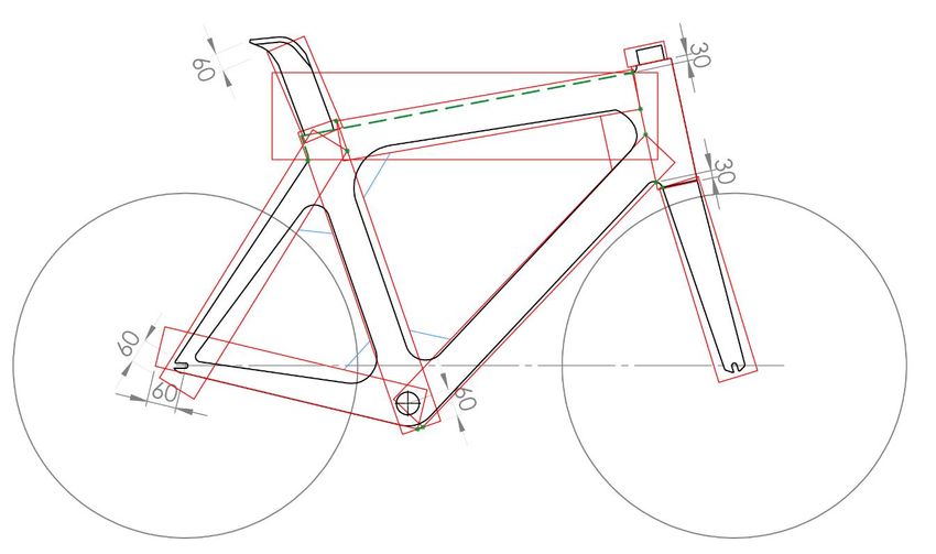
CLARIFICATION GUIDE OF THE UCI TECHNICAL REGULATION

When assessing a request for use of equipment which is not yet available for sale, the UCI
Equipment Unit will pay particular attention to safety of the equipment which will be
submitted to it for authorization.
The use of equipment designed especially for the attainment of a particular performance
(record or other) shall be not authorised.
Upon expiry of the authorized period of use of a prototype (equipment not yet available for
sale), any item of equipment must be commercially available in order to be used in cycling
events. The requirement of commercial availability shall be understood as equipment having
to be available through a publicly available order system (whether with manufacturer,
distributor or retailer). Upon an order being placed, the order shall be confirmed within 30
days and the relevant equipment shall be made available for delivery within a further 90-day
deadline. In addition, the retail price of the equipment shall be publicly advertised, shall not
render the equipment de facto unavailable to the general public and shall not unreasonably
exceed the market value for equipment of a similar standard.

Any equipment which is not commercially available and is not authorised (not authorised by
UCI Equipment Unit or authorised period expired), may not be used in cycling events
governed by the UCI Regulations. Any such unauthorised use of equipment may be
sanctioned by disqualification of results obtained when using the equipment and/or a fine
ranging from CHF 5’000 to 100’000.”
Text modified on 15.10.18
The entire used material must be accessible to all participants. All the components must be
available commercially (i.e. available on the market or sold directly by the manufacturer) at
the latest twelve months after their first use in competition. If such a deadline is requested
and accepted by the UCI, the manufacturer must publicly announce that the product in
question is being used in competition and when it will be available for sale. In all cases the
product must be in a final stage of development, very similar to the product that will be
marketed.
Thus, it is not allowed to use equipment in competition that is not either available on the
market or authorized by the UCI Equipment Unit and previously communicated by the
manufacturer (with a twelve months period for the marketing).
The use of equipment specially designed for a particular athlete, event or performance are
prohibited. "Specially designed" means a bicycle with a technical added value when
compared with other equipment.
No minimum production quantity or minimum price is defined for either bicycles or any
component parts.
It is also demanded to have reasonable prizes, meaning comparable to a similar product of a
same range.

                                                                                              8
CLARIFICATION GUIDE OF THE UCI TECHNICAL REGULATION

§ 4 Onboard technology
ARTICLE 1.3.006 BIS

“Onboard technology devices, which capture or transmit data, may be fitted on bicycles or
worn by riders subject to being authorised under the present article, without prejudice to
other provisions of the UCI Regulations. The present article concerns any device which
captures or transmits data as described below, including but not limited to sensors (worn or
ingested), transponders, rider information systems, telemetry devices.

1. Devices which capture or transmit the following types of data are authorised:
        - Positioning: information related to the location of the rider or the bicycle;
        - Image: still or moving images or footage captured from the bicycle (such devices
may only be fitted on the bicycle unless specific regulations of a given discipline authorise
devices being worn by riders);
        - Mechanical: information captured from the bicycle or any of its components,
including but not limited to power, speed, cadence, accelerometer, gyroscope, gearing, tyre
pressure.

2. Devices which capture or transmit the following physiological data are authorised:
heartrate, body temperature, sweat rate. The authorisation is, however, limited to
transmission protocols which enable only the rider concerned to view the data
during a competition.

3. Devices which capture other physiological data, including any metabolic values
such as but not limited to glucose or lactate are not authorised in competition.

The authorised capturing and transmitting of data as provided under this article shall not
enable a rider to view data of another rider. Likewise, teams shall only access data of their
riders, where such transmission is authorised, unless information pertaining to riders of other
teams is publicly available.

Any onboard technology device fitted on a bicycle must:

•   Be installed on a system designed for bicycles and not affect the certification of any item
    of the bicycle;
•   Not cause a risk for the safety of any rider and, therefore, be affixed in a manner that
    ensures it is not susceptible of inadvertently dismounting or is non-removable.

The UCI may grant derogations to any envisaged use of onboard technology which is not
authorised by the present article. Derogation requests shall be assessed, inter alia, in
consideration of criteria of equal access to equipment, sporting fairness and integrity, and
shall also comply with articles 1.3.001 to 1.3.006. Derogations may be limited to specific
events and riders or teams.

The UCI shall not be liable for any consequences deriving from the installation and use of
onboard technology equipment by licence holders, nor for any defects it may hold or its non-
compliance.

                                                                                             9
CLARIFICATION GUIDE OF THE UCI TECHNICAL REGULATION

For the sake of clarity, the present article does not govern or affect the ownership of the
various data, meaning that the capturing, use and/or exploitation of the data remains
subject to consent of the relevant rights’ holder.”

(Article introduced on 10.06.21)

This article defines the terms of the onboard technology equipment which has the ability to
collect or transmit data, information or images on the bicycles (transponder, camera, gps,
telemetry system...).
Such equipment is not considered as technological innovations in the sense of the article
1.3.004.
Moreover, as these equipment must be non-removable, they are considered as an integral
part of the weight of the bicycle, as defined in the article 1.3.019. They will be left on the
bicycle during a minimum bicycle weight check done by the Commissaires.

Section 2 : bicycles
§ 1 Principles

ARTICLE 1.3.007

“The bicycle is a vehicle with two wheels of equal diameter. The front wheel shall be
steerable; the rear wheel shall be driven through a system comprising pedals and a chain.
Exceptions to this rule may exist for certain cycling disciplines, in which case specific rules are
provided for in the respective discipline.”

Text modified on 01.01.19

The bicycle is a vehicle with two wheels which must be of equal diameter. Exception for MTB
where the two wheels can be of a different diameter.
The front wheel is steerable; the rear wheel is driven. The bicycle is propelled solely by a
system of pedals acting upon a chain. Only one chain may be used on the bicycle in order to
engage the transmission between the bottom bracket and the driven wheel.
The bicycle must be in "working order" with a steering system acting on the steerable wheel
and a propulsion system acting on the driven wheel by means of a circular movement
through a chainset comprising one or more chainwheels and two arms (cranks), arranged at
180°, one as an extension of the other, in the same plane.
ARTICLE 1.3.008

“The rider shall normally assume a sitting position on the bicycle. This position requires that
the only points of support are the following: the feet on the pedals, the hands on the
handlebars and the seat on the saddle.”

The use of a supplementary point of support such as a lumbar support achieved by an
excessive inclination of the saddle or the addition of a lumbar support component to the
saddle is not authorized in order to ensure fairness in competition.

                                                                                                10
CLARIFICATION GUIDE OF THE UCI TECHNICAL REGULATION
ARTICLE 1.3.009
“The bicycle should have handlebars which allow it to be ridden and maneuvered in any
circumstances and in complete safety.”
Bicycles used in road and cyclo-cross events must be fitted with an efficient braking system
that acts on both wheels (either simultaneously or independently) operated by two brake
levers. The use of a fixed gear in competition is prohibited. Bicycles shall have at least 89 mm
clearance between the pedal spindle and the front tire when turned to any position in
accordance with the requirements of the EN14781 safety standard to not be hindered when
turning.
Hydraulic brake systems on rims are authorized provided that their attachment to the
bicycle does not contravene any regulations (brake hoods must not become extensions,
etc.). Disc brake systems are authorized.
ARTICLE 1.3.010
“The bicycle shall be propelled solely, through a chainset, by the legs (inferior muscular
chain) moving in a circular movement, without electric or other assistance.”
Exceptions to this rule may exist for certain cycling disciplines, in which case specific rules are
provided for in the respective discipline.
In para-cycling, mechanical prostheses/orthopedic braces for upper or lower limbs can only
be used by athletes who have been evaluated in accordance with the UCI classification
procedure and who have Review (R) or Confirmed (C) status.
In no case may a mechanical prosthesis/orthopedic brace for the lower limbs be used
outside para-cycling events.”
Text modified on 01.01.19
The movement of the pedal axle around the bottom bracket axle must be completely
circular. Oval chainwheels are allowed if the path is circular with a crank arm geometry that
does not change.
The addition of mechanical or electrical systems that serve to assist the rider is prohibited.
Exception for the E-MTB discipline. The use of an electronic unit solely to change gears is
authorized provided that the attachment to the bicycle does not contravene any regulations.
All athletes, disabled or able-bodied, wanting to wear prosthesis or orthopaedic braces
should go through the classification procedure. Able-bodied athletes cannot the use
mechanical prostheses/orthopaedic braces because they would have NE (Not Eligible) status
according to the classification procedure.
Mechanical prosthesis/orthopaedic braces for lower limbs are prohibited in able-bodied
events. On the other hand, mechanical prostheses/orthopaedic braces for upper limbs will
be authorised (after evaluation) if they allow an improvement in handling skills compared to
a fixed prosthesis/orthopaedic brace. An athlete with a mechanical prosthesis/orthopaedic
11CLARIFICATION GUIDE OF THE UCI TECHNICAL REGULATION
brace for upper limbs can thus take part in able-bodied competition upon receiving
authorization from the integration procedure.
§ 2 Technical specifications
ARTICLE 1.3.011
“Except where stated to the contrary, the technical specifications given in the articles 1.3.011
to 1.3.025 shall apply to bicycles used in road, track and cyclo-cross racing.
The specific characteristics of bicycles used in mountain bike, BMX, BMX Freestyle, trials,
indoor cycling and paracycling for riders with disabilities are set out in the part regulating the
discipline in question.”
Figure 5: Illustration of the parts of the bicycle covered by Articles 1.3.011 to 1.3.025
ARTICLE 1.3.012
“A bicycle shall not measure more that 185 cm in length and 50 cm in width overall.
A tandem shall not measure more than 270 cm in length and 50 cm in width overall.”
The maximum width of 500 mm for the bicycle directly relates the maximum authorised
overall width (outside – outside) of handlebars. The minimum overall width (outside –
outside) of traditional handlebars (road events) and base bars (road and track events) is
limited to 350 mm.
12CLARIFICATION GUIDE OF THE UCI TECHNICAL REGULATION
ARTICLE 1.3.013
“The peak tip of the saddle shall be a minimum of 50 mm to the rear of a vertical plane
passing through the bottom bracket spindle.
The peak tip of the saddle can be moved forward until the vertical line passing through the
bottom bracket spindle where necessary for morphological reasons as a part of an
exemption. By morphological reasons should be understood everything to do with the size
and limb length of the rider.
Any rider who, for these reasons, considers theat he needs to use a bicycle of lesser
dimensions than those given shall inform the commissaires' panel to that effect at the time
of the bike check.
Only one (1) of the following two (2) exemptions for morphological reasons can be requested
by the rider and thereafter granted;
1. Either the peak tip of the saddle can be moved forward to a value distance equal to
or less than 50 mm.
2. Or tThe fixed time trial extensions handlebar can be adapted moved forward, in
accordance with the rider height categories defined in Article 1.3.023.”
The withdrawn position of the saddle is measured from the tip of the saddle to the vertical
plane passing through the center of the bottom bracket axle.
Any rider who considers, for morphological reasons, that he or she cannot respect the
regulations concerning the withdrawn position of the saddle may obtain an exemption from
the commissaire at the time of the bike check. In no case the peak of the saddle can exceed
the vertical line passing through the bottom bracket spindle
If the exemption for the saddle is used, the rider cannot use the exemption for the
extensions length in accordance with Article 1.3.023
13CLARIFICATION GUIDE OF THE UCI TECHNICAL REGULATION
ARTICLE 1.3.014
“The plane passing through the highest points at the front and rear of the saddle can have a
maximum angle of nine degrees from horizontal. The length of the saddle shall be 24 cm
minimum and 30 cm maximum. A tolerance of 5mm is allowed.”
It is important to grant the rider sufficient freedom to allow a comfortable position to be
adopted, reducing the pressure on the perineum, while avoiding any deviation through an
excessively sloping saddle that could improve sporting performance to an unacceptable
degree by the addition of a lumbar support. Furthermore, if the saddle is inclined too
severely, this reduces the quality of the rider’s position on the saddle, thus reducing its
intrinsic function of providing a basic support for the rider on the bicycle.
Checks on the horizontality of saddles are conducted in the road, track and cyclo-cross
events by measuring the angle of incline of the saddle, considering the plane passing
through the highest points at the front and rear of the saddle. This angle must be less than 9
degrees (positive or negative incline).
The commissaries are provided with a
measuring device as shown in the Figure
6. Checks will not be systematic, but in
the event of any doubt, the commissaires
will place the device on the saddle to
determine its angle of incline after having
calibrated the device to the ground or the
measuring jig. Figure 6: Official measuring device to
check saddle inclination
14The measurement of the horizontality of saddles must be a simple, fair and repeatable
process. The tolerance of 9 degrees gives the rider a lot of freedom to adjust his or her
position on the bike. Commissaires are able to give a clear, coherent and categorical
response when carrying out saddle checks.
ARTICLE 1.3.015
“The distance between the bottom bracket spindle and the ground shall be between 24 cm
minimum and maximum 30 cm.”
The aim of this rule, among other things, is to avoid the risk of the cranks or pedals touching
the ground when cornering.
ARTICLE 1.3.016
“The distance between the vertical passing through the bottom bracket spindle and the front
wheel spindle shall be between 54 cm minimum and 65 cm maximum.
The distance between the vertical passing through the bottom bracket spindle and the rear
wheel spindle shall be between 35 cm minimum and maximum 50 cm.”
If the front or rear center is too short, this will reduce the bicycle's stability whereas if the
front or rear center is too long the bicycle will be less manoeuvrable.
Figure 7: Illustration of the minimum and maximum distances between the bottom bracket
and front and rear wheel axles
ARTICLE 1.3.017
“The distance between the internal extremities of the front forks shall not exceed 11.5 cm;
the distance between the internal extremities of the rear triangle shall not exceed 14.5 cm.”
15CLARIFICATION GUIDE OF THE UCI TECHNICAL REGULATION
Figure 8: Illustration of the maximum distances between the fork drop-outs and rear drop-
outs
ARTICLE 1.3.018
“Wheels of the bicycle may vary in diameter between 70 cm maximum and 55 cm minimum,
including the tyre. For the cyclo-cross bicycle the width of the tyre (measured between the
widest parts) shall not exceed 33 mm and it may not incorporate any form of spike or stud.
For massed start competitions in the disciplines road and cyclo-cross, only wheel designs
granted prior approval by the UCI may be used. Wheels shall have at least 12 spokes; spokes
can be round, flattened or oval, as far as no dimension of their sections exceeds 10 mm.
In order to be granted approval wheels must have been subjected to the Vertical Drop Test
which consists of :
Test method : Vertical Drop Test
Vertical drop test (neutralization of the rebound of the anvil)
Energy level :
40 Joules
Impact striker geometry :
Flat steel anvil, the impact surface is covered with a silicone rubber pad of 20mm thickness
(Hardness Shore A=50 +/- 5, Compression set of 40% acc. To ASTM D395 Method B). The
rubber pad requires to be undamaged.
Impact mass :
Range of 6 – 10 kg
Energy must always remain at 40 Joules at the hit with a +/- 5% tolerance.
Hitting point :
16CLARIFICATION GUIDE OF THE UCI TECHNICAL REGULATION
One hit at 90° from valve hole, adjusted to have the impact point of anvil between the spokes
In order to be certified as passed, the alloy and/or carbon wheels shall have
- No visible cracks or delamination
- No change in lateral profile or in lateral run out in excess of 1.0mm
- No change in radial profile or in radial run out in excess of 1.0mm
Wheels which meet the definition of traditional wheels do not need to be certified.
Definition of Traditional wheels :
Criteria :
Rim height: less than 25 mm
Rim material: alloy
Spokes: minimum of 20 steel spokes which are detachable and all components must be
identifiable and commercially available
In track competition, including motor-pacing the use of a front disc wheel is only permitted in
the specialties against the clock
Notwithstanding this article, the choice and use of wheels remains subject to articles 1.3.001
to 1.3.003.”
This regulation applies to road races and cyclo-cross. There is a distinction between standard
and non-standard wheels. The latter must pass a vertical drop test using a specific procedure
in order to be included in the list of wheels authorized for competition. This document
entitled "List of Approved Wheels” and further detailed information on the test procedure
for non-standard wheels are available on the UCI website under the "Equipment" heading.
The procedure does not apply to time trials on the road or track events.
The list of approved wheels under the previous procedure, in force until the 31 December
2015, is also available on the UCI website under the “Equipment” heading. The wheels
included in this list are still allowed in competition.
For the individual sprint, the front disc wheel is allowed for the qualifications (200m flying
start) but not for the matches.
ARTICLE 1.3.019
“The weight of the bicycle cannot be less than 6.8 kilograms.”
The minimum weight of the bicycle (in
working order) is 6.800 kg, considered
without on-board accessories in place,
that is to say those items that may be
removed during the event. The bottles,
on-board computers and all others
removable accessories must be removed
during the weight check. However, the
bottle cages, fixture systems and clipped-
on extensions are part of the bicycle and Figure 9: Measuring the weight of a
stay in place during the weighing. bicycle
1718 CLARIFICATION GUIDE OF THE UCI TECHNICAL REGULATION
ARTICLE 1.3.020
TRIANGULAR SHAPE
“For road, track, and for cyclo-cross competitions, the frame of the bicycle shall be of a
traditional pattern, i.e. built around a main triangle.”
The triangular shape is defined from a design using 8 cm-wide boxes for each tube. In order
to comply with this rule, the nominal rear wheel axle must be located within the seat stay
and chain stay boxes. Furthermore, the bottom bracket axle must be located inside the chain
stay, seat tube and down tube boxes. The drawing below illustrates these conditions.
Figure 10: Illustration of the bottom bracket and rear wheel axles inside the corresponding
boxes
This rule results from the Lugano Charter and has the objective of preserving the culture and
image of the bicycle as an historical fact. Among other things, it prevents the use of "girder"
frames and bicycles with extravagant shapes that do not represent bicycles as understood by
the UCI and which would change the existing disciplines.
18CLARIFICATION GUIDE OF THE UCI TECHNICAL REGULATION
Figure 11: Example geometry of a bicycle that does not comply with UCI regulations
COMPENSATION TRIANGLES AND THE 16CM REINFORCEMENT ZONE
“Isosceles compensation triangles with two 8 cm sides are authorized at the joints between
frame elements except at the joints between the chain stays and seat stays where triangles
are not authorized.
The effective width of the head tube zone may not exceed 16 cm at the narrowest point
between the inner join of the top tube and down tube and the front of the box for the head
tube.”
Authorized reinforcement triangles are shown in blue in the diagram below. A 16 cm
reinforcement zone is defined for the section where the top tube, head tube and down tube
connect.
The frame can completely fill the areas (rectangular boxes, compensation triangles and the
16 cm reinforcement zone), but in no case cross these limits.
19CLARIFICATION GUIDE OF THE UCI TECHNICAL REGULATION
Figure 12: General illustration of compensation triangles and boxes
Reinforcement triangles with 8 cm sides are authorized at the joints between the tubes in
order to accommodate the stresses relating to the specific properties of composites which
require broader curves than metal to distribute and transmit forces through the frame
without creating stress concentration zones that would make the frame more dangerous to
use.
The 16 centimeters rule has been introduced to guarantee improved aerodynamic fairness in
competition between taller and shorter riders and in order to allow manufacturers enough
room for maneuver so that they can create a design which is consistent between different
frame sizes while allowing an adequate level of rigidity to guarantee safety in this sensitive
area of the frame.
To illustrate this amendment to the UCI technical regulations, a series of drawings will allow
all the possible situations to be clarified.
First, in the case of small frame sizes, even if the frame fits entirely within the boxes (shown
Figure 13), the distance between the front of the box for the head tube and the internal joint
between the top tube and the down tube at the nearest point to the head tube must not
exceed 16 cm.
In this specific instance, there is no compensatory joint zone that can be added to the boxes
behind the head tube, since, as its name indicates, there is no scope for compensation, given
how far forward the frame is. On the contrary, the 16 cm must be respected even inside the
boxes as illustrated in the drawings below.
20CLARIFICATION GUIDE OF THE UCI TECHNICAL REGULATION
Figure 13: Illustration of the 16cm rule
Figure 14: Illustration of the maximum Figure 15: Illustration of the maximum
distance of 16 cm for a small frame size distance of 16 cm for a small frame size
(A) (B)
The limit case where the 16 cm corresponds exactly to the intersection of the boxes for the
top and down tubes is shown in the Figure 16. In this configuration, no compensatory joint
zone can be added to the boxes behind the head tube.
21CLARIFICATION GUIDE OF THE UCI TECHNICAL REGULATION
Figure 16: Illustration of the limit case
Lastly, for average and large frame sizes, the compensatory triangle behind the head tube is
replaced by a compensatory joint zone of 16 cm. This zone is constructed by tracing a line
parallel to and 16 cm behind of the line of the front of the box for the head tube, between
the boxes for the top and down tubes, as shown in the Figure 17.
The compensatory joint zone thus makes it possible to design a more homogeneous
transition between the top tube and the down tube while permitting a better choice of the
tube size for larger frames. Thus, the aerodynamic advantage of small frames disappears
while at the same time avoiding taller riders making use of small frames to obtain this
benefit.
Figure 17: Illustration of the compensatory joint zone
22CLARIFICATION GUIDE OF THE UCI TECHNICAL REGULATION
STRAIGHT LINES
“It shall be constructed of straight or tapered tubular elements (which may be round, oval,
flattened, teardrop shaped or otherwise in cross-section) such that the form of each element
except the chain stays and the seat stays encloses a straight line.”
The frame tubes must be tubular without excessive curvature. The frame elements may be
slightly curved, but a straight line must be able to be drawn within each element along its
length. The start and finish points of each of these lines is shown on the diagram below.
Figure 18: Illustration of the start and finish points of the straight lines required inside tubes
The start and finish points of the lines inside frame elements are the following:
• Top tube: from the intersection of the front of the seat tube box with the top tube
to the intersection of the rear of the head tube box with the top tube.
• Head tube: from the section through the top of the head tube to the lower section
taken at the point of contact with the forks.
• Down tube: from the center of the bottom bracket to the intersection of the rear of
the head tube box with the down tube.
• Seat tube: from the center of the bottom bracket to the section passing through the
top of the seat tube.
In the case of double tubes, the straight line must fall within the envelope encompassing
both tubes. In this case, it is not obligatory to be able to insert a straight line within each
tube separately.
It is not necessary for a straight line to pass inside the chain stays, seat stays, and fork
blades.
THE SHAPE OF TUBES
“The elements of the frame shall be laid out such that the joining points shall follow the
following pattern: the top tube (1) connects the top of the head tube (2) to the top of the
23CLARIFICATION GUIDE OF THE UCI TECHNICAL REGULATION
seat tube (4); the seat tube shall connect to the bottom bracket shell; the down tube (3) shall
connect the bottom bracket shell to the bottom of the head tube. The rear triangles shall be
formed by the chain stays (6), the seat stays (5) and the seat tube (4) with the seat stays
anchored to the seat tube at points falling within the limits laid down for the slope of the top
tube. The seat post shall comply with the dimensional restrictions that apply to the seat tube
and may be attached to the frame anywhere on the seat tube and/or top tube. Additional
frame components can be added between the head tube and the handlebar stem. These
must be inside the dimension of the head tube box.”
The frameset must be able to fit entirely within the template formed by nine rectangular
boxes of 80 mm width, the 16 cm reinforcement zone and the compensation triangles as
shown by the diagram below. The seat post (8) must be able to fit entirely within its own
rectangular box of 80 mm width. The upper line of the box must pass at most 60 mm from
the fixture of the saddle on the seat post, Figure 20. Additional frame components between
the head tube and the handlebar stem which are not covered by the head tube box and/or
the top tube box must be able to fit within their own rectangular component box (9) of
80mm width. Altogether, the additional frame components between the head tube and the
handlebar stem cannot exceed dimensional restrictions of the head tube box. During the
transition stage, this restriction does not apply to additional frame components between the
head tube and the handlebar stem which, on 1 January 2021, are/were already at the
production stage.
Manufacturers are free to adjust the positioning of the boxes provided that the frame
geometry respects all articles of the technical regulations and the frame and forks are
entirely contained within the boxes and do not present any apparent dangers (protruding
parts or sharp angles).
The bicycle must be designed and adjusted in such a manner that the rider can adopt a
regulatory position as defined by Articles 1.3.022 and/or 1.3.023.
Figure 19: General illustration of the shape and positioning of the 8 cm boxes
24CLARIFICATION GUIDE OF THE UCI TECHNICAL REGULATION
A template formed by red boxes for each element is shown below. The points circled in
green show the limits of the box lengths. The head tube box must be positioned in the same
axis as the steerer tube.
Figure 20: Illustration of the template showing the start and finish points of the 8 cm boxes
for each element
The start and finish points of the 8 cm boxes are the following:
• Top tube: the front line of the box must pass through the point of intersection of the
rear line of the head tube box with the lower line of the top tube box; the rear line
of the box must pass through the point of intersection of the front line of the seat
tube box with the upper line of the top tube box.
• Head tube: the upper line of the box must pass no more than 30 mm above the
point of intersection of the rear line of the head tube box with the upper line of the
top tube; the lower line of the box must pass no more than 30 mm below the point
of intersection of the lower line of the down tube box with the rear line of the head
tube box.
• Down tube: the front line of the box must pass through the point of intersection of
the rear line of the head tube box with the upper line of the down tube box; the rear
line of the box must pass through the point of intersection of the lower line of the
seat tube box with the lower line of the down tube box.
• Seat tube: the upper line of the seat tube must not surpass the upper line of the top
tube except in the situation where the seat post extends from the upper line of the
seat tube; the lower line of the box must not be located in excess of 60 mm below
the bottom bracket center.
• Seat stays: the upper line of the box must pass through the point of intersection of
the front line of the seat tube box with the front line of the seat stay box; the lower
line of the box must not be located in excess of 60 mm below the rear wheel axle
center.
25CLARIFICATION GUIDE OF THE UCI TECHNICAL REGULATION
• Chain stays: the front line of the box must pass through the point of intersection of
the lower line of the seat tube box with the lower line of the chain stay box; the rear
line of the box must not be located in excess of 60 mm behind the rear wheel axle
center.
• Forks: the upper line of the box must pass through the lowest point of the head
tube; the lower line of the box can be positioned at the desired height provided that
the fork is completely contained within the box. The box of the down tube can be
used to cover the upper part of the fork.
• Seat post: the seat post must be attached at least with one point of contact with the
seat tube and/or top tube in the highlighted area (green). The start of the area:
point of intersection of the upper line of the top tube with the rear line of the head
tube box. The end of the area: point of intersection of the rear line of the seat stay
with the rear line of the seat tube. The upper line of the box must pass at most 60
mm from the fixture of the saddle on the seat post. The front and rear lines of the
seat post must not pass through any frame elements completely.
• Additional frame component between the head tube and the handlebar stem: the
lower line of the box must be collinear with the upper line of the head tube box; the
upper line of the box can be positioned at the desired height provided that the
component is entirely contained within the box.
Figure 21: Illustration of the positioning of the seat post box
Any extension of the tube boxes beyond the points described above in order to contain
certain frame parts is prohibited. For example, the extension of the top tube box behind the
seat tube, as shown in Figure 22, is prohibited. The red zone of the frame is not allowed
under the regulations and the red part of the top tube box must not be used.
Cable guides and the seat bolt do not have to be contained within the 8 cm boxes provided
that there is no deviation from their principal function. If these parts are integrated into the
frame, everything must fit inside the boxes.
2627 CLARIFICATION GUIDE OF THE UCI TECHNICAL REGULATION
Figure 22: Illustration of the unauthorized extension of the top tube box behind the seat tube
TUBE DIMENSIONS
“The maximum height of the elements shall be 8 cm and the minimum thickness 1 cm. The
minimum thickness of the elements of the front fork shall be 1 cm; these may be straight or
curved (7) .”
The terms "height" and "thickness" used in the article should be understood to be the
largest and smallest dimensions of tube sections respectively, i.e. the maximum and
minimum dimensions authorized in any direction. Thus, the maximum dimension of the
section of elements is 8 cm while the minimum dimension is 1 cm.
A tolerance of one millimeter is allowed for frame elements to account for the thickness of
surface coatings (paint and sponsors’ logos). No tolerance is allowed when inspecting
technical designs, in particular during approval procedures.
The blue areas of the illustration below show the parts of the frame and forks that must
respect the rule of minimum and maximum dimension for the tubes.
All sections must be perpendicular to the front or upper edges (red lines in the drawings).
27CLARIFICATION GUIDE OF THE UCI TECHNICAL REGULATION
Figure 23: Illustrations of the areas of the frameset subject to the rule of minimum and
maximum dimension
Sections A to O on the illustration represent the limits of these areas and are defined as
follows:
• Section A-A: a perpendicular section at the end of the top tube passing through the
point 80 mm from the front line of the seat tube box on the lower line of the top tube
box.
• Section B-B: a perpendicular section at the end of the top tube passing through the point
160 mm from the front line of the head tube box on the lower line of the top tube box.
• Section C-C: a perpendicular section at the end of the down tube passing through the
point 160 mm from the front line of the head tube box on the rear line of the down tube
box.
• Section D-D: a perpendicular section at the end of the down tube passing through the
point 80 mm from the front line of the seat tube box on the rear line of the down tube
box.
28CLARIFICATION GUIDE OF THE UCI TECHNICAL REGULATION
• Section E-E: a perpendicular section at the end of the seat tube passing through the
point 80 mm from the rear line of the down tube box on the front line of the seat tube
box.
• Section F-F: a perpendicular section at the end of the seat tube passing through the
point 80 mm from the front line of the seat stay box on the rear line of the seat tube box.
• Section G-G: a perpendicular section at the end of the seat stays passing through the
point 80 mm from the rear line of the seat tube box on the front line of the seat stay box.
• Section H-H: a perpendicular section at the end of the seat stays passing through the
point of intersection of the front line of the seat stay box with the upper line of the chain
stay box.
• Section I-I: a perpendicular section at the end of the chain stays passing through the
point of intersection of the front line of the seat stay box with the upper line of the chain
stay box.
• Section J-J: a perpendicular section of the chain stays passing through the point halfway
between the center of the bottom bracket and the rear wheel axle.
• Section K-K: a perpendicular section at the end of the fork blades located 50 mm from
the point where the fork blades join together.
• Section L-L: a perpendicular section at the end of the fork blades located 50 mm from
the front wheel axle.
• Section M-M (In case the seat post extends from the upper line of the seat tube): a
perpendicular section at the end of the seat tube on the part above the top tube passing
through the point 30 mm from the upper line of the top tube box on the front line of the
seat tube box.
• Section N-N: a perpendicular section of the seat post passing through the point of
intersection of the upper line of the top tube or its extension with the front or the rear
line of the seat post box.
• Section O-O: a perpendicular section of the seat post passing through the point 10mm
from the upper line of the seat post box on the front line of the seat post box.
The regulations do not concern the transition zones between tubes.
SLOPING TOP TUBE
“The top tube may slope, provided that this element fits within a horizontal template defined
by a maximum height of 16 cm.”
The top tube may be inclined (sloping) provided that this frame element is contained within
a horizontal box of 16 cm height. The limits of this zone are established as shown in the
diagrams below, i.e. upper limit by the intersection of the top tube with the head tube box
and lower limit by the intersection of the top tube with the seat tube box.
29CLARIFICATION GUIDE OF THE UCI TECHNICAL REGULATION
Figure 24: Illustration of maximum allowed sloping top tube
Figure 25: Lowest point (circled in green) Figure 26: Highest point (circled in green)
that must be contained within the 16 cm- that must be contained within the 16 cm-
high horizontal box high horizontal box
In addition to the requirement to fit within the 16 cm-high horizontal box, the top tube must
also fit within the 8 cm box.
INCLINATION OF SEAT STAYS
The front line of the 8 cm seat stay box must cross the area of intersection between the
horizontal 16 cm-high box and the 8 cm seat tube box. The rear wheel axle must be
contained within the seat stay and chain stay boxes.
30CLARIFICATION GUIDE OF THE UCI TECHNICAL REGULATION
Figure 27: Illustration of the rule on the inclination of seat stays
FORK GEOMETRY
When the fork comprises a steerer that is inserted inside the head tube, the fork is
considered as a separate component to the frame. Consequently, the fork must be
contained within a single box of 8 cm width (not including the steerer). This box starts at the
point of contact (circled in the Figure 28) between the head tube and the fork crown but is
not necessarily positioned in the same plane as the head tube.
When the fork is offset with the offset steerer component pivoting around its axis, it is
considered to be integrated with the frame and thus the moving part is not considered
separately from the structure of the frame. In this case the fixed and moving parts of the
offset fork arrangement must be wholly contained within the template for the head tube.
The axis of the head tube must always be contained within the head tube box in offset forks,
as illustrated in the Figure 29.
The body of the fork must be contained within a box although this can be offset in relation
to the head tube. This box starts at the point of contact (circled in the Figure 29) between
the head tube and the fork crown but is not necessarily positioned in the same plane as the
head tube. For safety reasons relating to the properties of composites, the templates of the
head tube and fork must overlap more than half the thickness of these boxes.
By no means can the boxes of the top tube or the down tube be used to cover a part of the
fork.
31CLARIFICATION GUIDE OF THE UCI TECHNICAL REGULATION
Figure 28: Illustration of the position of the boxes for a fork using a traditional internal
steerer
Figure 29: Illustration of the positioning of the axis of the head tube within the head tube box
3233 CLARIFICATION GUIDE OF THE UCI TECHNICAL REGULATION
Thus, forks considered separately from the frame must be able to be covered entirely by the
fork box in the case of a standard design forks, or by the fork box and the head tube box in
the case of an offset forks. The box of the down tube can be used to cover the upper part of
the fork box. It is prohibited to use other frame boxes to cover the fork components.
A protuberance integrated with the fork crown, that serves as a stem or a support for the
stem for the handlebars and handlebar extensions, is allowed but must be restricted to its
original function. A diversion of use in the form of an added extension is prohibited.
Figure 30: Illustration of the position of the boxes for offset fork
Figure 31: Illustration of a protuberance used as a stem.
33CLARIFICATION GUIDE OF THE UCI TECHNICAL REGULATION
MULTIPLE ELEMENTS
Multiple elements are authorized for the frame (top tube, down tube, seat tube, seat stays,
chain stays), the fork, the seat post.
The multiple tubes, taken individually and together, have to respect the maximum section
dimension of 8 cm and the minimum section dimension of 1 cm.
ARTICLE 1.3.022
“In competitions other than those covered by article 1.3.023, only the traditional type of
handlebars (see diagram «structure 1A») may be used. The handlebars must be positioned in
an area defined as follows: above, by the horizontal plane of the point of support of the
saddle (B); below, by the horizontal line plane passing 100 mm below the highest point of the
two wheels (these being of equal diameter) (C); at the rear by the axis of the steerer tube (D)
and at the front by a vertical line plane passing through at horizontal distance of 100 mm
from the axis of the front wheel spindle with a 5 cm tolerance (see diagram «Structure
(1A)»). The distance referred to in point (A) is not applicable to the bicycle of a rider who
takes part in a sprint event on track (flying 200 m, flying lap, sprint, team sprint, keirin, 500
metres and 1 kilometre), but must not exceed 10 cm in relation to the vertical line passing
through the front wheel spindle.
In addition, all handlebars must conform to the following:
- The maximum dimension of the cross section of the handlebars is 80 mm
- The maximum dimension of the cross section of the stem is 80 mm
- The minimum dimension of the cross section of all fork accessory is 10 mm
- Two isosceles compensation triangles with two 40 mm sides are authorised at the
joints between the stem and the handlebars.”
The traditional type of handlebars must be used in road races, cyclo-cross and track races
(apart from track time trials and pursuits). The attachment of any additional handlebar
component or fixed additional time trial extension handlebar is prohibited in these events.
In no case shall the front of the handlebars exceed the vertical plane passing at horizontal
distance of 100 mm from the the axis of the front wheel spindle; tolerance of 10 5 cm in
relation to a vertical line passing through the front wheel axle, which is the control zone of
the bicycle. The more forward the handlebar is positioned, the less maneuverable the
bicycle will be and the less it will be easy to react quickly to an obstacle or a wind gust.
Moreover, this would result in moving the center of gravity of the rider on the bicycle, which
would increase even more the risks of loss of control. The area of positioning the handlebars
is defined by the diagram below:
34You can also read