Geotechnical Manual - July 2020 2020 by Texas Department of Transportation (512) 463-8630 all rights reserved - Texas Department of ...
←
→
Page content transcription
If your browser does not render page correctly, please read the page content below
Geotechnical Manual

               July 2020
    © 2020 by Texas Department of Transportation
          (512) 463-8630 all rights reserved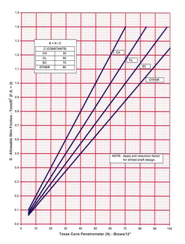
Manual Notice 2020-1
From: Graham Bettis, P.E., Director, Bridge Division
Manual: Geotechnical Manual
Effective Date: July 13, 2020
Purpose
This manual provides policy for geotechnical investigation and design for project development.
Contents
The revisions contained in each chapter of this version are to clarify the policy and high-level
procedures published in 2018. Generally, revisions to the manual were to:
Update information in Chapter 2 regarding investigation around suspected karst formations,
and provide more guidance when recording groundwater elevations during drilling operations.
Make minor changes to the laboratory testing protocol for shear strength determination in
Chapter 2.
Update procedure in Chapter 3 on ‘Drill Hole Filling’ with current standard practices using
mix of bentonite and/or grout.
Include limits of any needed Temporary Special Shoring in Retaining Wall layouts standard
specifications which would apply to Temporary Special Shoring in Chapter 6.
Eliminate prior soil parameter assumptions on nailed embankments to account for independent
analysis of wall systems in Chapter 6.
Highlight in Chapter 6 the importance of utilizing proper parameters in the RW(MSE)DD
sheet to standardize design.
Update the minimum criteria for nail diameters in rock nailed walls section in Chapter 6.
Provide greater clarification in Chapter 7 that global stability design factors of safety should be
at minimum 1.3 and 1.5.
Chapter 5 underwent significant revisions and updates, which include:
geologic layer terminology clarification in Sections 1 and 2;
updating guidance for Scour Summary Sheet and submission of Form 2605 into the bridge
inspection system;
updating method for calculating scour at bridge channels including reference to NCHRP
reports;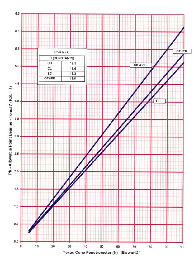
updating the scour guidance at bridge class culverts.
Supersedes
The revised manual supersedes prior versions of the manual.
Contact
For more information about any portion of this manual, please contact the TxDOT Bridge Division.
Archives
Past manual notices are available in a PDF archive.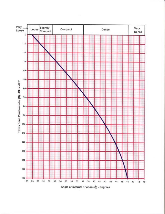
Table of Contents
Chapter 1 — Manual Overview
         Section 1 — About this Manual. . . . . . . . . . . . . . . . . . . . . . . . . . . . . . . . . . . . . . . . . . . . . . .                  1-2
          Purpose of the Manual . . . . . . . . . . . . . . . . . . . . . . . . . . . . . . . . . . . . . . . . . . . . . . . . . . . . .            1-2
          Updates . . . . . . . . . . . . . . . . . . . . . . . . . . . . . . . . . . . . . . . . . . . . . . . . . . . . . . . . . . . . . . . .    1-2
          Organization . . . . . . . . . . . . . . . . . . . . . . . . . . . . . . . . . . . . . . . . . . . . . . . . . . . . . . . . . . . .       1-2
          Feedback . . . . . . . . . . . . . . . . . . . . . . . . . . . . . . . . . . . . . . . . . . . . . . . . . . . . . . . . . . . . . . .     1-3

Chapter 2 — Soil Surveys
         Section 1 — Soil Surveys . . . . . . . . . . . . . . . . . . . . . . . . . . . . . . . . . . . . . . . . . . . . . . . . . . .              2-2
          Overview . . . . . . . . . . . . . . . . . . . . . . . . . . . . . . . . . . . . . . . . . . . . . . . . . . . . . . . . . . . . . . .     2-2
          Review of Existing Data . . . . . . . . . . . . . . . . . . . . . . . . . . . . . . . . . . . . . . . . . . . . . . . . . . .              2-2
          Hole Location . . . . . . . . . . . . . . . . . . . . . . . . . . . . . . . . . . . . . . . . . . . . . . . . . . . . . . . . . . .        2-2
          Bridges. . . . . . . . . . . . . . . . . . . . . . . . . . . . . . . . . . . . . . . . . . . . . . . . . . . . . . . . . . . . . . . . .   2-3
          Retaining Walls . . . . . . . . . . . . . . . . . . . . . . . . . . . . . . . . . . . . . . . . . . . . . . . . . . . . . . . . . .        2-4
          Other Structures . . . . . . . . . . . . . . . . . . . . . . . . . . . . . . . . . . . . . . . . . . . . . . . . . . . . . . . . . .       2-5
          Slopes and Embankments . . . . . . . . . . . . . . . . . . . . . . . . . . . . . . . . . . . . . . . . . . . . . . . . . .                 2-5

Chapter 3 — Field Operations
         Section 1 — Drilling . . . . . . . . . . . . . . . . . . . . . . . . . . . . . . . . . . . . . . . . . . . . . . . . . . . . . . .          3-2
          Overview . . . . . . . . . . . . . . . . . . . . . . . . . . . . . . . . . . . . . . . . . . . . . . . . . . . . . . . . . . . . . . .     3-2
          Access . . . . . . . . . . . . . . . . . . . . . . . . . . . . . . . . . . . . . . . . . . . . . . . . . . . . . . . . . . . . . . . . .   3-2
          Utility Clearance . . . . . . . . . . . . . . . . . . . . . . . . . . . . . . . . . . . . . . . . . . . . . . . . . . . . . . . . .        3-2
          Traffic Control . . . . . . . . . . . . . . . . . . . . . . . . . . . . . . . . . . . . . . . . . . . . . . . . . . . . . . . . . . .      3-2
          Drill Hole Filling . . . . . . . . . . . . . . . . . . . . . . . . . . . . . . . . . . . . . . . . . . . . . . . . . . . . . . . . .       3-3
         Section 2 — Sampling Methods . . . . . . . . . . . . . . . . . . . . . . . . . . . . . . . . . . . . . . . . . . . . . .                    3-4
          Overview . . . . . . . . . . . . . . . . . . . . . . . . . . . . . . . . . . . . . . . . . . . . . . . . . . . . . . . . . . . . . . .     3-4
         Section 3 — Field Testing . . . . . . . . . . . . . . . . . . . . . . . . . . . . . . . . . . . . . . . . . . . . . . . . . . .             3-5
          Texas Cone Penetration (TCP) Test . . . . . . . . . . . . . . . . . . . . . . . . . . . . . . . . . . . . . . . . . .                      3-5
          Standard Penetration Test (SPT) . . . . . . . . . . . . . . . . . . . . . . . . . . . . . . . . . . . . . . . . . . . . .                  3-5
          In-Place Vane Shear Test. . . . . . . . . . . . . . . . . . . . . . . . . . . . . . . . . . . . . . . . . . . . . . . . . . .              3-5
          Torvane and Pocket Penetrometer . . . . . . . . . . . . . . . . . . . . . . . . . . . . . . . . . . . . . . . . . . . .                    3-5

Chapter 4 — Soil and Bedrock Logging
         Section 1 — Logging . . . . . . . . . . . . . . . . . . . . . . . . . . . . . . . . . . . . . . . . . . . . . . . . . . . . . . .           4-2
          Material Order of Description . . . . . . . . . . . . . . . . . . . . . . . . . . . . . . . . . . . . . . . . . . . . . . .                4-2
          Material . . . . . . . . . . . . . . . . . . . . . . . . . . . . . . . . . . . . . . . . . . . . . . . . . . . . . . . . . . . . . . . .   4-2
          Density or Consistency, Hardness . . . . . . . . . . . . . . . . . . . . . . . . . . . . . . . . . . . . . . . . . . . .                   4-2
          Moisture. . . . . . . . . . . . . . . . . . . . . . . . . . . . . . . . . . . . . . . . . . . . . . . . . . . . . . . . . . . . . . . .    4-3

Geotechnical Manual                                                        i                                                        TxDOT 7/2020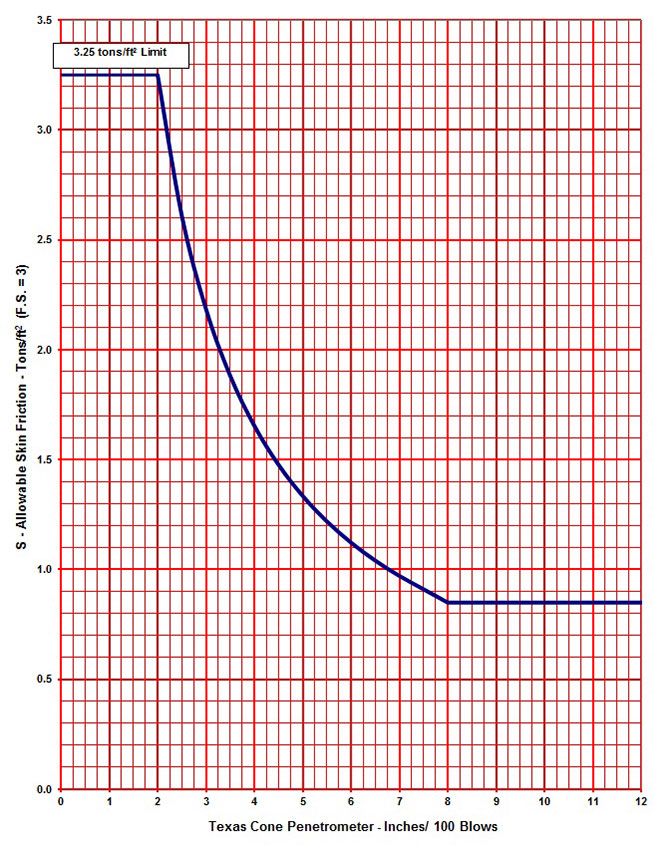
Color . . . . . . . . . . . . . . . . . . . . . . . . . . . . . . . . . . . . . . . . . . . . . . . . . . . . . . . . . . . . . . . . . . 4-3
Cementation. . . . . . . . . . . . . . . . . . . . . . . . . . . . . . . . . . . . . . . . . . . . . . . . . . . . . . . . . . . . . 4-3
Descriptive Adjectives. . . . . . . . . . . . . . . . . . . . . . . . . . . . . . . . . . . . . . . . . . . . . . . . . . . . . 4-3
Unified Soil Classification System (ASTM D2487) . . . . . . . . . . . . . . . . . . . . . . . . . . . . . . 4-3
Rock Quality Designation (RQD) and Percent Recovery . . . . . . . . . . . . . . . . . . . . . . . . . . 4-4
Log Form . . . . . . . . . . . . . . . . . . . . . . . . . . . . . . . . . . . . . . . . . . . . . . . . . . . . . . . . . . . . . . . 4-4
Chapter 5 — Foundation Design
Section 1 — Foundation Type Selection . . . . . . . . . . . . . . . . . . . . . . . . . . . . . . . . . . . . . . . . 5-2
Foundation Selection Factors . . . . . . . . . . . . . . . . . . . . . . . . . . . . . . . . . . . . . . . . . . . . . . . 5-2
Foundation Guidelines for Widening Structures . . . . . . . . . . . . . . . . . . . . . . . . . . . . . . . . . 5-3
Section 2 — Interpretation of Soil Data. . . . . . . . . . . . . . . . . . . . . . . . . . . . . . . . . . . . . . . . . 5-4
Overview . . . . . . . . . . . . . . . . . . . . . . . . . . . . . . . . . . . . . . . . . . . . . . . . . . . . . . . . . . . . . . . 5-4
Disregard Depth. . . . . . . . . . . . . . . . . . . . . . . . . . . . . . . . . . . . . . . . . . . . . . . . . . . . . . . . . . 5-4
Texas Cone Penetration Test . . . . . . . . . . . . . . . . . . . . . . . . . . . . . . . . . . . . . . . . . . . . . . . . 5-4
Laboratory Test . . . . . . . . . . . . . . . . . . . . . . . . . . . . . . . . . . . . . . . . . . . . . . . . . . . . . . . . . . 5-9
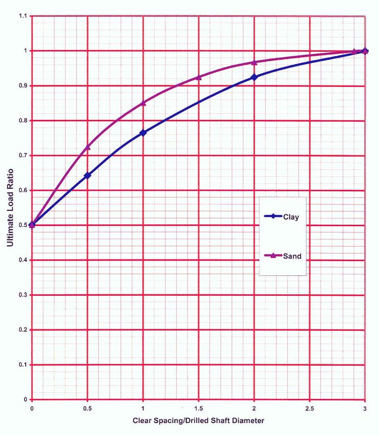
Section 3 — Drilled Shafts . . . . . . . . . . . . . . . . . . . . . . . . . . . . . . . . . . . . . . . . . . . . . . . . . 5-10
Overview . . . . . . . . . . . . . . . . . . . . . . . . . . . . . . . . . . . . . . . . . . . . . . . . . . . . . . . . . . . . . . 5-10
Belled Shafts . . . . . . . . . . . . . . . . . . . . . . . . . . . . . . . . . . . . . . . . . . . . . . . . . . . . . . . . . . . 5-10
Standing Water . . . . . . . . . . . . . . . . . . . . . . . . . . . . . . . . . . . . . . . . . . . . . . . . . . . . . . . . . 5-10
Wing Shafts . . . . . . . . . . . . . . . . . . . . . . . . . . . . . . . . . . . . . . . . . . . . . . . . . . . . . . . . . . . . 5-11
Service Loads. . . . . . . . . . . . . . . . . . . . . . . . . . . . . . . . . . . . . . . . . . . . . . . . . . . . . . . . . . . 5-11
Drilled Shaft Reinforcement . . . . . . . . . . . . . . . . . . . . . . . . . . . . . . . . . . . . . . . . . . . . . . . 5-11
Drilled Shaft Integrity Testing. . . . . . . . . . . . . . . . . . . . . . . . . . . . . . . . . . . . . . . . . . . . . . 5-12
Layout Notes . . . . . . . . . . . . . . . . . . . . . . . . . . . . . . . . . . . . . . . . . . . . . . . . . . . . . . . . . . . 5-12
Section 4 — Piling . . . . . . . . . . . . . . . . . . . . . . . . . . . . . . . . . . . . . . . . . . . . . . . . . . . . . . . . 5-14
Overview . . . . . . . . . . . . . . . . . . . . . . . . . . . . . . . . . . . . . . . . . . . . . . . . . . . . . . . . . . . . . . 5-14
Wing Piling . . . . . . . . . . . . . . . . . . . . . . . . . . . . . . . . . . . . . . . . . . . . . . . . . . . . . . . . . . . . 5-14
Steel Piling Special Considerations . . . . . . . . . . . . . . . . . . . . . . . . . . . . . . . . . . . . . . . . . . 5-14
Difficult Driving . . . . . . . . . . . . . . . . . . . . . . . . . . . . . . . . . . . . . . . . . . . . . . . . . . . . . . . . 5-15
Service Loads. . . . . . . . . . . . . . . . . . . . . . . . . . . . . . . . . . . . . . . . . . . . . . . . . . . . . . . . . . . 5-15
Dynamic Monitoring . . . . . . . . . . . . . . . . . . . . . . . . . . . . . . . . . . . . . . . . . . . . . . . . . . . . . 5-15
Section 5 — Foundation Load Testing . . . . . . . . . . . . . . . . . . . . . . . . . . . . . . . . . . . . . . . . 5-17
Section 6 — Scour . . . . . . . . . . . . . . . . . . . . . . . . . . . . . . . . . . . . . . . . . . . . . . . . . . . . . . . . 5-18
Analysis . . . . . . . . . . . . . . . . . . . . . . . . . . . . . . . . . . . . . . . . . . . . . . . . . . . . . . . . . . . . . . . 5-18
New Bridges with Known Foundations. . . . . . . . . . . . . . . . . . . . . . . . . . . . . . . . . . . . . . . 5-18
Existing Bridges with Known Foundations. . . . . . . . . . . . . . . . . . . . . . . . . . . . . . . . . . . . 5-21
Existing Bridges with Unknown Foundations. . . . . . . . . . . . . . . . . . . . . . . . . . . . . . . . . . 5-21
Bridge Class Culverts . . . . . . . . . . . . . . . . . . . . . . . . . . . . . . . . . . . . . . . . . . . . . . . . . . . . 5-21
Geotechnical Manual ii TxDOT 7/2020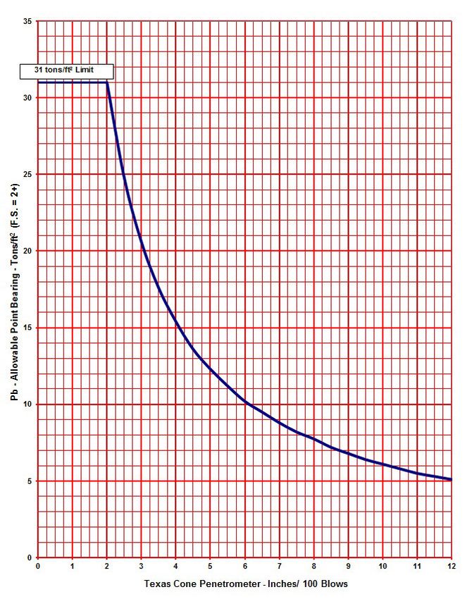
Scour Critical Bridges . . . . . . . . . . . . . . . . . . . . . . . . . . . . . . . . . . . . . . . . . . . . . . . . . . . . 5-22
                 Stone Protection at Bridges . . . . . . . . . . . . . . . . . . . . . . . . . . . . . . . . . . . . . . . . . . . . . . . . 5-22

Chapter 6 — Retaining Walls
         Section 1 — Retaining Wall Selection . . . . . . . . . . . . . . . . . . . . . . . . . . . . . . . . . . . . . . . . .                         6-2
          Overview . . . . . . . . . . . . . . . . . . . . . . . . . . . . . . . . . . . . . . . . . . . . . . . . . . . . . . . . . . . . . . .        6-2
         Section 2 — Retaining Wall Layouts . . . . . . . . . . . . . . . . . . . . . . . . . . . . . . . . . . . . . . . . . .                         6-3
          General Content Layout. . . . . . . . . . . . . . . . . . . . . . . . . . . . . . . . . . . . . . . . . . . . . . . . . . . .                 6-3
          Plans for Specific Wall Types . . . . . . . . . . . . . . . . . . . . . . . . . . . . . . . . . . . . . . . . . . . . . . .                   6-4
         Section 3 — Design Considerations . . . . . . . . . . . . . . . . . . . . . . . . . . . . . . . . . . . . . . . . . . .                        6-7
          General Design . . . . . . . . . . . . . . . . . . . . . . . . . . . . . . . . . . . . . . . . . . . . . . . . . . . . . . . . . .            6-7
          Design Criteria for Specific Wall Types . . . . . . . . . . . . . . . . . . . . . . . . . . . . . . . . . . . . . . .                         6-7
               Section 4 — Excavation Support . . . . . . . . . . . . . . . . . . . . . . . . . . . . . . . . . . . . . . . . . . . . .                6-14
                Overview . . . . . . . . . . . . . . . . . . . . . . . . . . . . . . . . . . . . . . . . . . . . . . . . . . . . . . . . . . . . . .   6-14
                Trench Excavation Protection . . . . . . . . . . . . . . . . . . . . . . . . . . . . . . . . . . . . . . . . . . . . . .               6-14
                Temporary Special Shoring . . . . . . . . . . . . . . . . . . . . . . . . . . . . . . . . . . . . . . . . . . . . . . . .              6-14

Chapter 7 — Slope Stability
         Section 1 — Overview . . . . . . . . . . . . . . . . . . . . . . . . . . . . . . . . . . . . . . . . . . . . . . . . . . . . . .               7-2
          Overview . . . . . . . . . . . . . . . . . . . . . . . . . . . . . . . . . . . . . . . . . . . . . . . . . . . . . . . . . . . . . . .        7-2
         Section 2 — Analysis and Design . . . . . . . . . . . . . . . . . . . . . . . . . . . . . . . . . . . . . . . . . . . . .                      7-3
          Global Stability Analysis. . . . . . . . . . . . . . . . . . . . . . . . . . . . . . . . . . . . . . . . . . . . . . . . . . .                7-3

Geotechnical Manual                                                         iii                                                        TxDOT 7/2020
Chapter 1 — Manual Overview

Contents:
     Section 1 — About this Manual

Geotechnical Manual                  1-1              TxDOT 07/2020
Chapter 1 — Manual Overview Section 1 — About this Manual
Section 1 — About this Manual
Purpose of the Manual
The purpose of this manual is to guide districts in geotechnical investigation and design for project
development. Recommendations, background information, and examples for geotechnical designs
are available on the TxDOT website.
Updates
Updates to this manual are summarized in the following table.
Table 1-1: Manual Revision History
Version Publication Date Summary of Changes
2000-1 August 2000 New Manual
2006-1 August 2006 Revision restructuring the manual to include policy and high-
level procedures, with recommendations, examples, and
background information now available on the Internet.
2012-1 December 2012 Clarification to policy previously established.
2018-1 March 2018 Clarification to policy previously established and updated
material in Chapters 3, 4, 5, 6 and 7.
2020-1 March 2020 Clarification to policy previously estab-
lished and updated material in Chapters 2,
3, 4, 5, 6 and 7.
Organization
Information in this manual is organized into the following chapters:
1. Manual Overview. Introductory information on the purpose and organization of the manual.
2. Soil Surveys. Requirements for conducting soil surveys for projects with bridges, retaining
walls, slopes and embankments, sign structures, illumination, sound walls, and radio towers.
3. Field Operations. Requirements for drilling, sampling, and field testing.
4. Soil and Bedrock Logging. Description of material order, level of description, and
classification.
5. Foundation Design. Guidelines for selecting foundation types, drilled shafts, piling, and
requirements for scour analysis.
Geotechnical Manual 1-2 TxDOT 07/2020Chapter 1 — Manual Overview Section 1 — About this Manual
6. Retaining Walls. Requirements for retaining wall selection, layouts, design, and excavation
support.
7. Slope Stability. Requirements for slope stability design and analysis.
Feedback
Direct any questions or comments on the content of this manual to the Director of the Bridge
Division, Texas Department of Transportation.
Geotechnical Manual 1-3 TxDOT 07/2020Chapter 2 — Soil Surveys
Contents:
Section 1 — Soil Surveys
Geotechnical Manual 2-1 TxDOT 07/2020Chapter 2 — Soil Surveys Section 1 — Soil Surveys
Section 1 — Soil Surveys
Overview
Conduct soil surveys for projects with the following features:
Bridges
Retaining walls
Slopes and embankments
Sign structures
Illumination
Sound walls
Radio towers
Perform minimum required testing for all structures, including Texas Cone Penetration (TCP)
testing at 5-ft. intervals and at strata changes, as well as Rock Quality Designation (RQD) and
percent recovery in rock. See the remaining portions of this chapter for requirements for all
explorations.
Review of Existing Data
Review all existing data before determining new data requirements. Old bridge plans are the most
common source of information. Old borings containing strength data are usually adequate for new
construction. If old borings are used for design, show the old boring data on the plans, and note the
date of the boring. Old TCP data may have an additional value listed: the weight of the drill stem
when the test was performed. Disregard this number and do not show it if the old borings will be
shown in the new plans.
Hole Location
The complexity of geological conditions and the type, length, and width of a structure determine
the number of holes required for foundation exploration.
Locate the test holes in an accessible area. When determining the location of test holes, always
avoid overhead power lines and underground utilities. If possible, avoid steep slopes and standing
or flowing water. Deviations within a 20-ft. radius of the staked location are not usually excessive,
but note them on the logs and obtain the correct surface elevation.
When determining the location and depth of test holes, carefully consider the following factors:
Geotechnical Manual 2-2 TxDOT 07/2020Chapter 2 — Soil Surveys Section 1 — Soil Surveys
Test hole depth
Lowering of gradeline
Channel relocations and channel widenings
Scour
Foundation loads
Foundation type
Bridges
The following figure shows the minimum number of test holes for common types of bridge
structures. Do not space test holes more than 300 ft. apart.
Figure 2-1. Minimum number of test holes for common types of structures
In general, drill test holes 15 to 20 ft. deeper than the probable tip elevation of the foundation.
Estimate the probable founding or tip elevation from the results of Texas Cone Penetration tests and
correlation graphs in Texas Cone Penetration Test and experience with foundation conditions in the
area. Pay special attention to major structures where high foundation loads are expected. If the
depth of the boring is questionable, consult the Bridge Division for a detailed analysis of the
projected foundation loads and foundation capacities.
Stream Crossings. Structures over channels less than 200 ft. wide are classified as minor stream
crossings. For these crossings, place a boring on each bank as close to the water’s edge as possible.
Geotechnical Manual 2-3 TxDOT 07/2020Chapter 2 — Soil Surveys Section 1 — Soil Surveys
If boring information varies significantly from one side of the channel to the other, a boring in the
channel may be necessary.
Major stream crossings require core borings in the channel if no existing data is available. A site
inspection by the driller or logger is necessary to evaluate site accessibility and special equipment
needs.
Karst Features. Structures suspected to be in a karst formation may
require more borings or geophysical survey.
Grade Separations. If the structure borings indicate soft surface soils (fewer than 10 blows per
foot), additional borings and testing may be required for the bridge approach embankments.
Bridge Field Exploration. The exploration should include the following:
Test hole spacing. Space test holes near each abutment of the proposed structure plus a
sufficient number of intermediate holes to determine the depth and location of all significant
soil and rock strata. If you do not get a reasonable correlation between borings (for example,
TCP data, stratigraphy), consult with the project engineer to determine the need for additional
holes.
Texas Cone Penetration tests. Conduct Texas Cone Penetration tests at 5-ft. intervals beginning
at a 5-ft. depth. Standard penetration test data is not acceptable for foundation design using the
TxDOT design procedure.
Near surface soil layer test. Test soft near surface soil layers (0 to 20 feet) as directed under the
subsection in this chapter titled Slopes and Embankments.
Soil and bedrock classification. Fill out a complete soil and bedrock classification and log
record for each test hole on the standard log, including all information to complete the form.
Ground water. Include ground water elevation measurements (including date of measurement)
as part of the data acquisition. Obtain the groundwater elevation minimum 15
minutes after the initial encounter with ground water. Site condi-
tions may require installation of piezometers to establish a true ground water surface elevation
and method of monitoring water surface fluctuations.
Retaining Walls
Obtain soil core borings for walls taller than 10 ft. Evaluate walls shorter than 10 ft. on a case-by-
case basis. TCP testing alone may be adequate to design walls and evaluate wall stability for short-
term loading conditions in cohesive profiles and short-term and long-term loading conditions in
cohesionless and rock profiles. A more rigorous sampling and testing program may be required for
long-term evaluation of walls founded on cohesive soil.
Geotechnical Manual 2-4 TxDOT 07/2020Chapter 2 — Soil Surveys Section 1 — Soil Surveys
Soil Borings. Obtain soil borings at 200-ft. spacing unless site conditions or the wall designer
requires tighter or coarser spacing.
Boring Depth for Fill Walls. For MSE walls, spread footing walls, temporary earth walls, and
block walls, bore to a depth as deep as the height of the wall depending on wall type and existing
and proposed ground lines. The minimum boring depth is 15 ft. below the bottom of the wall unless
rock is encountered. Extending borings 5 ft. into rock for fill walls is usually adequate.
Boring Depth for Cut Walls. For drilled shaft walls, tied-back walls, and soil and rock nail walls,
always base the depth of boring on the final grade lines. Cantilever drilled shaft walls require the
depth of boring to extend the anticipated depth of the shaft below the cut, which is typically
between one and two times the height of the wall. Advance borings for soil nail and rock nailed
walls through the material that is to be nailed. Extend borings a minimum of 20-ft. below the
bottom of the proposed wall. Borings for cut walls may need to penetrate rock significant distances
depending on the depth of the cut and height of the wall.
Soil Samples and Testing. Provide additional testing for taller walls, walls on slopes, or walls on
soft foundations as necessary to completely evaluate wall stability. Additional testing includes but
is not limited to obtaining samples for consolidation testing, triaxial testing, or in-place shear
testing to determine soil strength. Consult with the wall designer for development of the complete
soil exploration plan.
Ground Water. Include ground water elevation measurements (including date of measurement) as
part of the data acquisition for retaining walls. Obtain the groundwater elevation
minimum 15 minutes after the initial encounter with ground water.
Site conditions may require the installation of piezometers to establish a true ground water surface
elevation and method of monitoring water surface fluctuations.
Other Structures
Conduct foundation investigations for high-mast illumination, radio towers, and overhead sign
structures when other borings are not located nearby. The typical depth of the boring ranges from
30 to 70 ft. but depends on existing and proposed ground lines, soil strength, and structure
loading.
Slopes and Embankments
Soil Core Borings. Obtain soil core borings for cuts greater than 10 ft. or embankments taller than
15 ft. in areas with suspect foundation soils (less than or equal to 10 blows/ft.). TCP testing alone
may be adequate.
The exploration should include the following:
Geotechnical Manual 2-5 TxDOT 07/2020Chapter 2 — Soil Surveys Section 1 — Soil Surveys
The soil under future embankments. Advance borings to a depth equal to the height of the
embankment or 20 ft., whichever is greater. Conduct TCP testing at 5-ft. intervals.
Soil in proposed cuts. Advance borings to a depth of 15 ft. below the bottom of the proposed
cut. Conduct TCP testing at 5-ft. intervals.
Ground water elevation measurements. Include ground water elevation measurements (includ-
ing date of measurement) as part of the data acquisition for slopes and embankments. Obtain
the groundwater elevation minimum 15 minutes after the initial
encounter with ground water. Site conditions may require installation of piezome-
ters to establish a true ground water surface elevation and method of monitoring surface
fluctuations.
Soil Testing. Perform the appropriate field and laboratory tests necessary to determine the soil
shear strength for proper soil evaluation of the structure being designed. Consider both the short-
term and long-term conditions:
Short-term conditions. Use the Texas Cone Penetration test, in-place vane shear tests, uncon-
solidated undrained (UU) triaxial tests, and or direct shear tests.
Long-term conditions. Use consolidated undrained (CU) triaxial tests with pore pres-
sure measurement and/or drained direct shear tests.
Estimate long-term strengths of clay soils based on the index properties of the soil. Use the
following figure to correlate Texas Cone Penetration test results to angle of internal friction for
cohesionless soil.
Geotechnical Manual 2-6 TxDOT 07/2020Chapter 2 — Soil Surveys Section 1 — Soil Surveys
Figure 2-2. TCP vs. Angle of Internal Friction for Cohesionless Soils
Geotechnical Manual 2-7 TxDOT 07/2020Chapter 3 — Field Operations
Contents:
Section 1 — Drilling
Section 2 — Sampling Methods
Section 3 — Field Testing
Geotechnical Manual 3-1 TxDOT 07/2020Chapter 3 — Field Operations Section 1 — Drilling
Section 1 — Drilling
Overview
Consider the following items before starting core drill operations:
Core drill equipment
Drill rig
Site preparation
Access
Utility clearance
Traffic control
Barge work
Drill hole filling
Access
Ensure that permission to enter private property has been secured before drilling.
Utility Clearance
Clear all locations proposed for drilling for utilities before the core drill team arrives. When utilities
are present, ensure their exact locations are clearly marked by the utility company.
Call 1-800-545-6005 for utility clearance. Calls to this number automatically rotate to the three
notification centers. Obtain utility clearance at least 48 hours and no more than 14 days before
starting core drilling. You may contact the three notification centers directly as follows:
Texas Excavation Safety System (TESS) 1-800-344-8377
Lone Star Notification Center 1-800-669-8344
Texas One Call 1-800-245-4545
Traffic Control
Provide traffic control in accordance with Texas Manual on Uniform Traffic Control Devices for
approval prior to drilling.
Geotechnical Manual 3-2 TxDOT 07/2020Chapter 3 — Field Operations Section 1 — Drilling
Drill Hole Filling
Fill or plug drill holes using bentonite pellets or cement bentonite grout to
prevent injury to livestock or people in the area and to minimize the entry of surface water into the
bore hole. If surface contamination of lower aquifers or cross contamination is a concern, backfill
the hole with bentonite pellets or grout. This is especially important in urban areas where ground
contamination from leaking underground storage tanks is common. To avoid potential
settlement or uplift of pavement core, backfill all borings under
existing pavement shall be backfilled with bentonite pellets or
cement bentonite grout to a minimum depth of 6 inches below the
bottom of pavement structure. Then patch the hole with non-shrink
grout to the top of pavement.
Geotechnical Manual 3-3 TxDOT 07/2020Chapter 3 — Field Operations Section 2 — Sampling Methods
Section 2 — Sampling Methods
Overview
Use appropriate sampling methods as dictated by field conditions and laboratory tests. Provide
continuous sampling between Texas Cone Penetration testing for visual classification when drilling
methods allow.
Geotechnical Manual 3-4 TxDOT 07/2020Chapter 3 — Field Operations Section 3 — Field Testing
Section 3 — Field Testing
Texas Cone Penetration (TCP) Test
Conduct TCP testing in accordance with test procedure TEX 132-E Texas Cone Penetration Test.
Ensure that the drill rig mobilized to the drill site is equipped with test equipment that conforms to
the test procedure. Use a hammer with an automated trip mechanism to regulate the fall of the
hammer to 24 in. plus or minus 1/2 in.
TCP values described in this manual are either the total number of blows necessary to drive the
cone 12 in. or the distance the cone advances in inches in 100 blows.
Standard Penetration Test (SPT)
The use of SPT testing for foundation design is acceptable for design methodologies in AASHTO.
Conduct SPT tests in accordance with ASTM D-1586.
In-Place Vane Shear Test
Use the in-place vane shear test to determine the in-place shearing strength of fine-grained soil,
which does not lend itself to undisturbed sampling and triaxial testing. Use this test when
encountering organic silty clay (muck) or very soft clay. Ensure these materials are free of gravel or
large shell particles because pushing the vanes through these obstructions would disturb the sample
and probably cause physical damage to the vanes. Use the test with extreme caution in soil that has
Texas Cone Penetration values harder than 15 blows/12 in. Correct the vane shear results to the soil
index properties.
Torvane and Pocket Penetrometer
These two test devices are useful for index and classification purposes. They yield only
approximate information and are not suitable for foundation design.
Geotechnical Manual 3-5 TxDOT 07/2020Chapter 4 — Soil and Bedrock Logging
Contents:
Section 1 — Logging
Geotechnical Manual 4-1 TxDOT 07/2020Chapter 4 — Soil and Bedrock Logging Section 1 — Logging
Section 1 — Logging
Material Order of Description
Keep core descriptions as simple as possible. The order of description is as follows:
1. Material
2. Density or consistency, hardness
3. Moisture
4. Color
5. Cementation
6. Descriptive adjectives
7. Unified Soil Classification System
8. Rock Quality Designation (RQD), percent recovery
Material
Keep the number of strata to a minimum. Remember that every small variation in a soil—such as a
change in clay from “slightly sandy” to “sandy”—does not necessarily warrant a strata change. The
logger must define strata that have significance to designers and contractors who will use the core
log information. Designers and contractors are mainly interested in the primary and secondary soil
or rock constituent and whether ground water is present.
Density or Consistency, Hardness
Use the following charts to determine the density or consistency and hardness of material
encountered.
Table 4-1: Soil Density or Consistency
Density Consistency
(Cohesionless) (Cohesive) TCP Values Field Identification
Very loose Very soft 0 to 8 Core (height twice diameter) sags under own weight
Loose Soft 8 to 20 Core can be pinched or imprinted easily with finger
Slightly compact Stiff 20 to 40 Core can be imprinted with considerable pressure
Compact Very stiff 40 to 80 Core can be imprinted only slightly with fingers
Dense Hard 80 to 5 in./100 Core cannot be imprinted with fingers but can be
penetrated with pencil
Geotechnical Manual 4-2 TxDOT 07/2020Chapter 4 — Soil and Bedrock Logging Section 1 — Logging
Table 4-1: Soil Density or Consistency
Density Consistency
(Cohesionless) (Cohesive) TCP Values Field Identification
Very dense Very hard 0 in. to 5 in./100 Core cannot be penetrated with pencil
Table 4-2: Bedrock Hardness
Mohs’
Hardness Approximate TCP
Scale Characteristics Examples Hardness Values
5.5 to 10 Rock will scratch knife Sandstone, chert, schist, granite, Very hard 0 in. to 2 in./100
gneiss, some limestone
3 to 5.5 Rock can be scratched with Siltstone, shale, iron deposits, most Hard 1 in. to 5 in./100
knife blade limestone
1 to 3 Rock can be scratched with Gypsum, calcite, evaporites, chalk, Soft 4 in. to 6 in./100
fingernail some shale
Moisture
If any moisture exists, note the extent present. The samples will be assumed dry if the degree of
moisture is not indicated. If free water is present, describe the soil as wet or water-bearing.
Color
Describe the primary color, and restrict description to one color. If one main color does not exist in
a sample, call it multicolored.
Cementation
Identify the degree of cementation if any is present.
Descriptive Adjectives
Use any descriptive adjectives that might further aid in the description.
Unified Soil Classification System (ASTM D2487)
This soil system is based on the recognition of the type and predominance of the constituents
considering grain size, gradation, plasticity index, and liquid limit. It contains three major divisions
of soil: coarse-grained, fine-grained, and highly organic. See ASTM D2487, Standard Practice for
Classification of Soils for Engineering Purposes (Unified Soil Classification System), for the
Geotechnical Manual 4-3 TxDOT 07/2020Chapter 4 — Soil and Bedrock Logging Section 1 — Logging
procedure for determining soil classification. TxDOT test procedures, Tex-141-E, Manual
Procedure for Description and Identification of Soils and Tex-142-E, Laboratory Classification of
Soil for Engineering Purposes may also prove useful in the determination of soil type.
Rock Quality Designation (RQD) and Percent Recovery
Determine the RQD for rock core samples following ASTM Test Procedure D6032, Standard Test
Method for Determining Rock Quality Designation (RQD) of Rock Core. Always note the RQD
and percent recovery on logs of borings where rock is encountered.
Log Form
For uniformity, use the standard log form 513, Drilling Log. Group the materials encountered into
strata consisting of the same or similar constituents.
Geotechnical Manual 4-4 TxDOT 07/2020Chapter 5 — Foundation Design
Contents:
Section 1 — Foundation Type Selection
Section 2 — Interpretation of Soil Data
Section 3 — Drilled Shafts
Section 4 — Piling
Section 5 — Foundation Load Testing
Section 6 — Scour
Geotechnical Manual 5-1 TxDOT 07/2020Chapter 5 — Foundation Design Section 1 — Foundation Type Selection
Section 1 — Foundation Type Selection
Foundation Selection Factors
The designer is responsible for selecting the appropriate bridge foundation. Consider the following
factors in that selection:
Design load. The magnitude of the design load dictates the required size of the foundation
from a structural standpoint.
Subsurface stratigraphy. The depth and strength of subsurface stratigraphy deter-
mine the type of foundation chosen. In general, drilled shafts are well suited to areas with
competent soil and rock. While drilled shafts have been successfully installed in soft soil, they
may be less efficient than piling. In general, use piling where softer soil is present. Very hard
material at or near the surface makes driven pile installation difficult.
Corrosive conditions. Salts, chlorides, and sulfates are detrimental to foundations. Where these
conditions exist, take preventive measures. Use sulfate-resistant concrete as defined in
Standard Specification Item 421 for construction in seawater or soils with high sulfate content.
Consult the list of recommended corrosion protection areas for specific areas of Texas that may
have structures with possible corrosion due to sulfate soil or salt water. The use of steel piling
in corrosive environments is not recommended. If steel piling must be used, an appropriate
protective coating must be selected, additional steel section provided or a combination of these
methods utilized to ensure proper performance of the foundation elements.
Economic considerations. Consider economics in the final selection. Compare the foundation
types. The cost of a drilled shaft foundation, for instance, may be less than piling. It may be
feasible to use fewer piles at higher design loads, or fewer drilled shafts with larger diameters
to maximize economy. If no clear economic difference exists between piling and drilled shafts,
you may choose to include both and offer the contractor alternate designs in the contract plans.
Superstructure type. The type of superstructure chosen for the bridges may dictate or eliminate
certain foundation types. For instance, short-span structures over streams may work well with
trestle piling, but tall, single column flyovers justify footings with multiple shafts or piling.
Special design requirements. Special designs are sometimes necessary to straddle another
structure or utilities and may require a different type of foundation than the rest of the
structure.
Design foundations of new bridges as either drilled shafts or piling. Study all the available soil data,
and choose the type of foundation most suitable to the existing soil conditions and the particular
structure.
Geotechnical Manual 5-2 TxDOT 07/2020Chapter 5 — Foundation Design Section 1 — Foundation Type Selection
Foundation Guidelines for Widening Structures
Study test-boring data along with any available information regarding the existing foundation,
including but not limited to drilled shaft or pile driving records. Usually, old test-boring data is
adequate for widening the structure. In widening structures, consider special designs to prevent
differential movement between the new and the old foundations. This is normally accomplished by
founding the new foundations at approximately the same elevation as the existing foundations, if
applicable. Do not use piling in widening structures founded on spread footings.
Widening Structures on Piling. Widen structures on piling with piling tipped in the same stratum,
when possible. If loads for piling supporting the widened portion of the structure are the same or
lower than loads for the original construction, tip the new piling at approximately the same eleva-
tion as the existing piling. If new loads are higher, longer or larger piling may be required. Avoid
extreme variations between the new and existing tip elevations to minimize differential movement.
Widening Structures on Drilled Shafts. Widen structures on shafts with shafts at approximately
the same tip elevations. Often existing structures with belled shafts may be widened with straight
shafts tipped at the same elevation due to current higher allowable soil design loads and use of skin
friction in drilled shaft design.
Widening Structures on Spread Footings. The most critical situation occurs when widening a
structure founded on spread footings. If the existing footings are less than 6 ft. below natural
ground and on rock, widen with spread footings at the same elevation. For abutment and interior
bents on deep spread footings, widening with drilled shafts is usually more economical with the
shafts founded near the existing footing elevation. This is not always practical, as in the case of
widening a structure on spread footings with drilled shafts. In a case like this, evaluate the soil for
shrink/swell potential.
Geotechnical Manual 5-3 TxDOT 07/2020Chapter 5 — Foundation Design Section 2 — Interpretation of Soil Data
Section 2 — Interpretation of Soil Data
Overview
A critical step in foundation design is determining strata and reasonable strengths to be assigned to
each stratum. Divide the subsurface materials into strata based on material description and test
values. Review all tests within each stratum to evaluate the variability of the data. If a single,
unusually high strength test is present among a group of distinctly lower test values, disregard the
anomalous test value. An average strength may be assigned for an entire layer as long as the test
values are reasonably similar.
Avoid defining very thick strata with widely variable test values. Subdivide thick strata with test
values varying from soft near the top to distinctly harder toward the bottom into two or more strata
with compatible values. Failure to subdivide may result in an unconservative average strength
being applied to foundations that terminate in the upper zone of that stratum.
An acceptable option to producing average unit values for strata is to calculate using a more
rigorous, test-by-test basis.
Disregard Depth
Disregard surface soil in the design of drilled shafts and piling foundations. The disregarded depth
is the amount of surface soil that is not included in the design of the foundation due to potential
erosion from scour, future excavation, seasonal soil moisture variation (shrinkage and swelling),
lateral migration of waterways, and other factors. Disregard a minimum amount of 5 ft. over non-
water crossings and 10 ft. over stream crossings. For abutments, disregard the portion of foundation
passing through embankment fills.
It is important to note that for projects where the existing ground line is at an elevation considerably
higher than the proposed grade line (roadway is to be depressed) soil softening, swelling or heave
must be accounted for in design of embankment slopes, roadways, retaining walls and foundation
elements. Soils in these conditions respond to the removal of overburden (unloading). This
response could have a dramatic impact on the design approach taken.
Additional information regarding disregarded depth is available online.
Texas Cone Penetration Test
Use the following charts to determine skin friction and point-bearing capacity based on Texas Cone
Penetration data for drilled shaft and piling designs. Use Figure 5-1 to determine allowable skin
Geotechnical Manual 5-4 TxDOT 07/2020Chapter 5 — Foundation Design Section 2 — Interpretation of Soil Data
friction for soil softer than 100 blows/12 in. Select the curve based on the description of the soil
type.
Use the CH curve in clay soil identified as high-plasticity, or fat clay. Use the CL curve in clay soil
identified as low-plasticity, or lean clay. In clay soil, use the CL curve if no specific identification is
provided regarding plasticity. Use the SC curve for soil described as either sandy clay or clayey
sand. Use the OTHER curve for soils described as silt, sand, gravel or any layers not
fitting into one of the previous designations.
For drilled shaft designs, multiply the allowable design stress by a reduction factor of 0.7. The
reduction factor is used to account for disturbance of the soil during drilling. Application of the
reduction factor to the design of driven piling is not necessary.
Geotechnical Manual 5-5 TxDOT 07/2020Chapter 5 — Foundation Design Section 2 — Interpretation of Soil Data
Figure 5-1. Allowable Skin Friction (TCP Values Softer than 100 Blows/12 in.)
Use Figure 5-2 to determine allowable point bearing for soil softer than 100 blows/12 in. Select the
curve based on the description of the soil type, using the criteria noted for the previous chart.
Geotechnical Manual 5-6 TxDOT 07/2020Chapter 5 — Foundation Design Section 2 — Interpretation of Soil Data
Figure 5-2. Allowable Point Bearing (TCP Values Softer than 100 Blows/12 in.)
Use Figure 5-3 to determine allowable skin friction for soil or rock strata harder than 100
blows/12 in. The upper limit of 3.25 tons/ft2 applies for all Texas Cone Penetration values less than
2 in/100 blows. Do not apply skin friction reduction factor to values obtained from this figure
because this figure is derived only for use in drilled shaft design. Piling typically cannot be driven
into soil of this strength, so this figure is not generally used for piling design.
Geotechnical Manual 5-7 TxDOT 07/2020Chapter 5 — Foundation Design Section 2 — Interpretation of Soil Data
Figure 5-3. Allowable Skin Friction (TCP Values Harder than 100 Blows/12 in.)
Use Figure 5-4 to determine allowable point bearing for soil or rock strata harder than 100
blows/12 in. The upper limit of 31 tons/ft2 applies for all Texas Cone Penetration values less than 2
in/100 blows.
Geotechnical Manual 5-8 TxDOT 07/2020Chapter 5 — Foundation Design Section 2 — Interpretation of Soil Data
Figure 5-4. Allowable Point Bearing (TCP Values Harder than 100 Blows/12 in.)
Laboratory Test
If additional strength data is available from triaxial or direct shear testing, use this data with TCP
data in the design of foundations. Determine the ultimate shear strength for each stratum using
Coulomb’s formula (Shear Strength = τ = c’ + y’ (tan ϕ’). Determine allowable skin friction by
applying a factor of safety of at least 2.0 to the ultimate shear strength. For drilled shaft design,
reduce the allowable skin friction value by an additional reduction factor of 0.7 to account for soil
disturbance. Determine allowable point bearing by multiplying the ultimate shear strength by a
bearing capacity factor of 9 and then dividing by a factor of safety of at least 2.0.
Geotechnical Manual 5-9 TxDOT 07/2020Chapter 5 — Foundation Design Section 3 — Drilled Shafts
Section 3 — Drilled Shafts
Overview
Consider both skin friction and point bearing in drilled shaft design. Calculate total allowable skin
friction by multiplying the perimeter of the shaft by the unit value for allowable skin friction
derived from Figure 5-1, Figure 5-3, or laboratory data or any combination thereof. Apply a
reduction factor of 0.7 to allowable skin friction values derived from Figure 5-1 or from laboratory
testing. Do not apply the reduction factor to allowable skin friction values obtained from Figure 5-
3. Accumulate skin friction along the length of the shaft beginning at the previously defined
disregard depth and continuing down to the tip of the shaft. Calculate total allowable point bearing
by multiplying the area of the drilled shaft times the unit value for allowable point bearing derived
from Figure 5-2, Figure 5-4, or laboratory data. If softer layers exist within two shaft diameters of
the proposed tip, use allowable point bearing values for the softer layers. If drilled shafts are to be
tipped in very hard material that is overlain by soft strata, the skin friction contribution of the softer
strata may be disregarded in design. However, do not ignore the contribution of significant amounts
of competent material in order to tip in rock. In many areas of the state, rock is overlain by thick
layers of material that can support considerable loads.
Belled Shafts
Belled drilled shafts are no longer used as a foundation element for bridge foundations. Therefore,
do not use belled shafts for bridge foundation design.
Standing Water
Drilled shafts installed in lakes or rivers require use of a casing placed from above the water surface
to a minimum embedment into the river or lake bottom. Do not define the top of the drilled shaft in
the normal manner (a set distance below finished grade). Define the top of the drilled shaft as 1 to 2
ft. above the normal water elevation. If the water level is variable, add a provision allowing the top
of the drilled shaft to be adjusted based on water level at the time of construction. Allow casing
required for construction to remain in place at the option of the contractor. Typically, casings left in
place look no worse than the stained concrete shaft that will be visible if casings are removed. If
casing is to be left in place, disregard skin friction along the length of the casing. If permanent
casing is used in standing water, consideration should be given to painting the portion of casing
extending above the mud line.
Geotechnical Manual 5-10 TxDOT 07/2020Chapter 5 — Foundation Design Section 3 — Drilled Shafts
Wing Shafts
Found wing shafts in similar founding material as abutment shafts to minimize the potential for
differential settlement.
Service Loads
See the following table for maximum drilled shaft service loads recommended without conducting
a detailed structural analysis. Before final structural design, review the soil information to verify
the ability of the foundation to develop desired loads.
Table 5-1: Maximum Allowable Drilled Shaft
Service
Size Load
24 in. 175 tons
30 in. 275 tons
36 in. 400 tons
42 in. 525 tons
48 in. 700 tons
54 in. 900 tons
60 in. 1,100 tons
66 in. 1,350 tons
72 in. 1,600 tons
84 in. 2,175 tons
96 in. 2,850 tons
108 in. 3,625 tons
120 in. 4,475 tons
Drilled Shaft Reinforcement
Drilled shaft reinforcement is to be designed for axial, lateral, and uplift load. The reinforcement
will follow the details on the FD Standard, unless site specific designs are required which require
alternate reinforcement. The longitudinal reinforcement for the drilled shaft will extend the full
length of the shaft.
Geotechnical Manual 5-11 TxDOT 07/2020Chapter 5 — Foundation Design Section 3 — Drilled Shafts
Drilled Shaft Integrity Testing
Various testing methods are available to determine the integrity of drilled shafts, which are
Crosshole Sonic Logging, Gamma-Gamma testing, and Thermal Integrity Profiling (TIP). TIP is
the preferred testing method, as it is done during the curing of the concrete and does not delay
construction. Bridge Division has developed a Special Specification for TIP testing titled “Thermal
Integrity Profiler (TIP) Testing of Drilled Shafts.”
TIP testing should be considered for use under the following conditions:
Mono-shafts;
Large diameter shafts (60” diameter, or greater);
Drilled shafts with a diameter > 24 inches encountering water bearing sands in the soil profile
and on critical roadways, such as interstate systems, high ADT roadways, emergency routes,
evacuation routes, etc.
Consult with the Geotechnical Branch to determine if a specific project might be considered a
candidate for TIP testing.
Layout Notes
When drilled shaft capacity depends heavily on penetrating a specific hard layer, add a plan note
instructing the contractor and field personnel of the penetration requirement. If no specific
penetration into a hard layer is required, no plan note is necessary:
Hard founding layer at depth: When a hard founding layer is expected to be present more than
three shaft diameters below the surface, specify a minimum penetration of one shaft diameter
on the plans if the design load is reached at this location. Increase this minimum penetration if
additional skin friction is required to fulfill the design requirements.
Typical notes on bridge layouts:
"Found drilled shafts a minimum of one shaft diameter into hard rock," or
"Found drilled shafts at the elevations (lengths) shown or deeper (longer) to obtain a
minimum XX drilled shaft diameter penetration into hard rock," where XX is determined
by the design.
The designer can use the control of elevation or length if elevations are not called out on the
layout. Expand the words "hard rock" to distinguish the type of material anticipated. Although
not a common practice, the first note allows a drilled shaft to be shortened if rock is encoun-
tered at higher than anticipated elevations, and it requires the shaft to be lengthened if rock is
not encountered where expected.
Rock at surface: When rock is present at or near the surface, consider load-carrying capacity
along with the stability of the superstructure on the foundation. For these shafts, a minimum
Geotechnical Manual 5-12 TxDOT 07/2020Chapter 5 — Foundation Design Section 3 — Drilled Shafts
shaft length of three shaft diameters is recommended. That is, a minimum three-diameter shaft
length, not a three-diameter penetration into rock. The final length of the drilled shafts should
be based on both axial and lateral loading (if required). If the potential scour extends down to
the top of rock then the minimum embedment of the drilled shaft should be three shaft
diameters or deeper to obtain the required axial and lateral capacity.
A typical note on bridge layouts reads, "Found drilled shafts at the elevation (length) shown or
deeper (longer) as necessary to obtain a minimum of three shaft diameter penetration into hard
rock."
The designer can use the control of elevation or length if elevations are not called out on the
layout. Expand the words "hard rock" to distinguish the type of rock. This note does not allow
a drilled shaft to be shortened from plan length, but it does require lengthening if rock is not
encountered at the expected elevation.
Plan notes should be specific as to the type of material to be penetrated. If more than one material is
likely to be encountered, it is acceptable to have multiple descriptions, such as “into dense sand,
sandstone, and/or shale.” Avoid using vague terms such as “hard strata” or “founding material.” In
stream or river environments, the channel flow line and estimated depth of scour should be
considered in determining the final shaft length and necessary penetration.
Geotechnical Manual 5-13 TxDOT 07/2020Chapter 5 — Foundation Design Section 4 — Piling
Section 4 — Piling
Overview
Piling design should consider skin friction and may consider point bearing as well. Because piling
has small tip areas and is generally placed in softer soil, the point bearing contribution is modest
and is often disregarded in design.
Calculate total allowable skin friction by multiplying the perimeter of the pile by the unit value for
allowable skin friction derived from Figure 5-1, Figure 5-3, or laboratory data or a combination
thereof. The maximum recommended value for allowable skin friction for piling design is 1.4 tons
per square foot (TSF). Accumulate skin friction along the length of the pile beginning at the
previously defined disregard depth and continuing down to the tip of the pile. If using point
bearing, calculate total allowable point bearing by multiplying the area of the pile times the unit
value for allowable point bearing derived from Figure 5-2, Figure 5-4, or laboratory data. If softer
layers exist within two shaft diameters of the proposed tip, use allowable point bearing values
based on the softer layers. Displacement piling refuses to advance when it encounters material with
TCP values harder than 100 blows/12 in. On refusal, assume that the piling has developed the
maximum allowable service load for the pile.
Take care when designing piling in areas with shallow hard or dense soils. If piling cannot be
driven through these areas, the contractor will need to pilot hole or jet the piling to achieve the
desired penetration.
Wing Piling
Found wing piling in similar founding material as abutment shafts to minimize the potential for
differential settlement.
Steel Piling Special Considerations
Grade Separations:
Foundation elements for grade separations are subject to potential vehicular impact the
use of steel sections in a trestle configuration in those potential impact zones is highly
discouraged. Instead for grade separations, steel H piling can potentially be used under
pile footings for interior bents or for abutments.
Stream Crossings:
Foundation elements for stream crossings are subject to scour, drift impact and have a
higher propensity for corrosion. For stream crossings, steel piling needs to be analyzed for
potential corrosion over the life span of the structure and need to be evaluated for both
axial and lateral loadings under the scoured condition. Steel piling that have been
Geotechnical Manual 5-14 TxDOT 07/2020Chapter 5 — Foundation Design Section 4 — Piling
evaluated for the above conditions and found to be acceptable could be used for trestle
bents. However, the steel piling must be coated to a minimum depth of 15 feet below the
maximum predicted scour elevation. Steel piling can be used to support pile footings as
long as the footing is embedded at a depth below the maximum predicted scour depth thus
minimizing the risk of exposure. Piling used in a footing configuration must be coated a
minimum distance of 15' below the bottom of footing. Piling can be used for foundation
elements for abutments.
Difficult Driving
If it is necessary to advance the piling through a strong or stiff layer where refusal is possible, a pile
penetration note may be required. A typical note may read, “The contractor’s attention is drawn to
the hard material in the soil profile, jetting and/or pilot holes may be necessary to advance the
piling to the required penetration depth.”
Service Loads
See the following table for maximum piling length and structural loads recommended without
conducting a detailed structural analysis. Many soils are not capable of developing these maximum
loads. Before final structural design, review the soil information to verify the ability of the
foundation to develop desired maximum loads.
Table 5-2: Maximum Allowable Pile Service Loads
Abutments and
Size Maximum Length Trestle Bents Footings (per Pile)
16 in. 85 ft. 75 ton 125 tons
18 in. 95 ft. 90 tons 175 tons
20 in. 105 ft. 110 tons 225 tons
24 in. 125 ft. 140 tons 300 tons
Dynamic Monitoring
Dynamic monitoring of a pile during driving can be accomplished using a Pile Driving Analyzer
(PDA) testing system. PDA testing measures the strain and acceleration in the pile as a result of the
impact of the hammer. PDA testing of a pile can help to determine the stresses in the pile during
driving and monitor the pile for damage or integrity. The capacity of the pile and time dependent
changes in capacity (if a restrike is undertaken) can be obtained if the PDA testing data is used with
the Case Pile Wave Analysis Program (CAPWAP).
Geotechnical Manual 5-15 TxDOT 07/2020Chapter 5 — Foundation Design Section 4 — Piling
Not all piling will require dynamic monitoring. However, for critical structures, projects with a
large number of piling, or in difficult soil conditions PDA testing should be considered for use.
Consult with the Geotechnical Branch to determine if a specific project might be considered as a
candidate for PDA testing.
Geotechnical Manual 5-16 TxDOT 07/2020Chapter 5 — Foundation Design Section 5 — Foundation Load Testing
Section 5 — Foundation Load Testing
Foundation load testing is a reliable means of determining the capacity of the foundation elements.
Foundation load testing is governed by Standard Specification Item 405. The various testing
methods that can be used are:
static load testing,
high strain dynamic testing, and
statnamic testing.
Not all foundations will require foundation load testing. Typically, load testing of foundation
elements is used in conjunction with Thermal Integrity Profiler (TIP) testing. Consult with the
Geotechnical Branch prior to using foundation load testing on a project.
Geotechnical Manual 5-17 TxDOT 07/2020Chapter 5 — Foundation Design Section 6 — Scour
Section 6 — Scour
Analysis
All bridges over waterways require a scour evaluation and a completed Scour Sum-
mary Sheet. The Scour Summary Sheet must be signed and sealed by an
engineer and entered into the bridge inspection management system
(BIMS) by District Bridge Inspection Staff. Scour evaluation docu-
mentation must also be entered into the BIMS. The results of the scour
evaluation will determine the Bridge Inspection Coding for Item 113 – Scour. The table below
defines the minimum scour design flood frequencies and scour design check flood frequencies for a
given hydraulic design flood frequency. These values are to be used to ensure that a bridge will
remain stable for a given design flood frequency.
Table 5-3: Hydraulic Design, Scour Design, and Scour Design Check Flood Frequencies
Hydraulic Design Flood Scour Design Flood Scour Design Check Flood
Frequency, QD Frequency, QS* Frequency, QC*
Q10 Q25 Q50
Q25 Q50 Q100
Q50 Q100 Q200
Q100 Q200 Q500
* Use the values listed or the overtopping event, whichever is the lower event.
New Bridges with Known Foundations
Evaluate new bridges with known foundations for potential scour in accordance with the following:
Guidelines outlined in Evaluating Scour at Bridges (HEC-18).
Do not use abutment scour equations because none of the equations to date yield
acceptable results. Use contraction scour equations to calculate total
scour at abutments. Protect abutments against potential scour through use of a flexible
revetment, where possible.
Determine scour at bridges using the following analysis techniques:
Use the following table to determine susceptibility of competent rock to scour when it is
present at moderate to shallow depths. Consider materials deemed either not susceptible or
Geotechnical Manual 5-18 TxDOT 07/2020You can also read