STRENGTHENING HERITAGE TUNNELS TO ENHANCE THE RESILIENCE OF WELLINGTON'S TRANSPORT NETWORK - Seismic Ratings for Degrading ...
←
→
Page content transcription
If your browser does not render page correctly, please read the page content below

97
                       Bulletin of the New Zealand Society for Earthquake Engineering, Vol. 54, No. 2, June 2021

                  STRENGTHENING HERITAGE TUNNELS TO ENHANCE
                   THE RESILIENCE OF WELLINGTON’S TRANSPORT
                                   NETWORK

                  Eleni Gkeli1, Pathmanathan Brabhaharan2, Dejan Novakov3,
                         Siva Arumugam4 and Gunasekaran Mookaiya5
                               (Submitted October 2020; Reviewed December 2020; Accepted April 2021)

                                                                 ABSTRACT
               Wellington city is characterised by steep hilly terrain, and as such several tunnels have been constructed since
               the beginning of the last century to provide critical transport access in the city. These tunnels are still used
               today as part of the city’s transport routes, while also being an integral part of the city’s history and heritage.
               Wellington is among the most seismically active areas in New Zealand. Three major active faults located
               within the Wellington Region and the proximity to the subduction zone are the main contributors to the high
               seismicity. The aging tunnels were designed and constructed prior to the advent of earthquake design
               standards and are subject to deterioration. Hence, they require maintenance and strengthening to ensure
               operational integrity and resilience to earthquake and other hazard events. Authorities have been supported
               by the authors in managing the risk through identifying key vulnerabilities, and prioritisation and
               implementation of strengthening measures. Best practice investigation and strengthening techniques have
               been applied through the process to ensure resilience and cost effectiveness.
               The paper presents case histories that highlight the value of investigations and assessment in understanding
               the risks, and novel strengthening measures developed to enhance resilience while preserving the heritage of
               the tunnels. Case histories include the seismic strengthening of the Hataitai Bus Tunnel, the Northland and
               Seatoun road tunnels and the investigation and assessment of the iconic Wellington Cable Car tunnels.

                        INTRODUCTION
The performance of transportation networks in earthquakes and
their ability to continue to function for the benefit of society has
been receiving increased attention in New Zealand. Wellington
Region is characterised by rugged terrain and, as a result,
tunnels are common and an integral part of important lifeline
infrastructure. Most of these tunnel structures were constructed
in the early 1900s, before the development of seismic design
standards, and are subject to aging and deterioration. Therefore,
seismic assessment and upgrade help extend their operational
lives and enhance resilience to earthquake and other hazards.

     RESILIENCE OF WELLINGTON’S TRANSPORT
                   NETWORK

Geology, Geomorphology and Seismotectonic Environment
New Zealand is a tectonically very active land mass due to its
position at the boundary between the Pacific and Australian
plates. The relative plate motion is expressed in New Zealand
by the presence of numerous active faults, a high rate of small-
to-moderate (magnitude M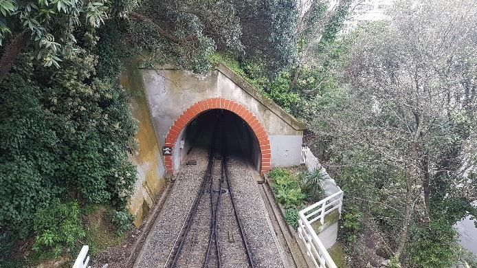
98

The Wellington Region is one of the most seismically active             Engineering Lifelines study [3]. This study assessed the
areas in New Zealand. The active faults located within the              vulnerability of the Wellington Region’s transport system to a
region, such as the Wellington, Ohariu and the Wairarapa                major earthquake scenario (a magnitude M7.5 Wellington Fault
faults, as well as the proximity to the subduction zone are the         event) and identified sections of the routes at high risk.
main contributors to the high seismicity (Figure 2).
                                                                        In 2001-2006, New Zealand research into strategies to manage
                                                                        the natural hazards risks to road networks led to the
                   Kapiti Coast                                         development of the concept of resilience for roads, together
                                                                        with metrics to measure resilience, using a geospatial platform
                                                                        [4]. A parallel study of the resilience of the Wellington City
                                                                        road network was carried out for Wellington City Council [5].
               Porirua
                                                                        The key conclusion of the resilience studies for Wellington City
                                                                        is that access in and out of the city, as well as between suburbs
                                            Upper Hutt                  within the city, will be closed in the event of a large earthquake
                                                                        by landslides and slope failures, as well as failures of structures,
                                                                        such as retaining walls, bridges and tunnels. The closures are
                             Lower Hutt                                 expected to be for several months. Given the terrain, many of
                                                                        the routes in Wellington lack redundancy, and therefore
                                                                        response and recovery after an event will be severely
                                                                        jeopardised. The resilience issues associated with existing
                Wellington
                                                                        infrastructure assets would therefore need to be addressed.

                                                                         WELLINGTON CITY TRANSPORTATION TUNNELS
                                                                        Wellington City Council developed a strategy to enhance the
                                                                        resilience of the road network and since 2001 has been
                                                                        implementing a targeted long-term programme of strengthening
       Figure 2: Active faults in the Wellington region.                important assets in its urban transport network [4,5]. The
                                                                        authors assisted the Council to assess the resilience of their
The region is underlain by a rock complex commonly known as             assets and to develop the strengthening strategy, and have
Wellington Greywacke, consisting of sandstone, siltstone,               continued to assist in the implementation of strengthening
mudstone (argillite) and localised volcanic rocks. The rocks are        works.
metamorphosed, highly deformed and variably weathered,
often with a high degree of fracturing and shearing [2]. The            Part of this program were the four tunnels owned by Wellington
Wellington Region is also characterised by rugged terrain.              City Council, Hataitai, Karori, Northland and Seatoun. These
                                                                        tunnels provide access between its key suburbs through
Urban infrastructure development in this terrain requires               Wellington’s hilly terrain and were assessed as critical
important transport routes to be associated with high cut slopes,       structures. This paper presents the investigation, assessment
retaining walls and tunnel structures. The active tectonic              and strengthening of the Hataitai, Northland and Seatoun
environment, the steep rugged terrain and tectonically                  tunnels. Details of these tunnels are shown in Table 1.
deformed and fractured rocks contribute to the vulnerability of
transport infrastructure in a variety of natural hazards such as        In addition, the seismic assessment and development of
storms, landslides, and earthquakes. The vulnerability of               strengthening concepts for the tunnels along the Wellington
transportation networks in similar terrain has been distinctively       Cable Car line are also presented in this paper (see Table 1).
demonstrated in the 14 November 2016 M7.8 Kaikoura                      The Cable Car is not a major transportation route, but consists
earthquake event, where significant cut slope failures,                 an iconic historical feature of Wellington City, a tourist
landslides, and damage to tunnels and other structures caused           attraction, and provides ease of direct public transport up the
one of the primary roads and railway corridors in New Zealand           hill to Kelburn from the central business district. The line is
to remain closed for many months, while significant and costly          operated by the Wellington Cable Car Company, which is a
remediation measures were required to restore access and                council-controlled organisation (CCO) owned by Wellington
functionality.                                                          City Council. The company is investing in the assessment of
                                                                        seismic performance, upgrading and maintenance of the Cable
                                                                        Car line to ensure functionality and life safety.
Road Network Resilience Context in Wellington City
Studies of the resilience of transportation networks of the             All the tunnels discussed in this paper are recognised as heritage
Wellington Region started in the early 90s, with the Wellington         structures in the Heritage New Zealand List [6] and/or the
                                                                        Wellington City District Plan [7]. The tunnels were originally

                  Table 1: Heritage tunnels of the Wellington urban transportation network discussed in this paper.

                    Managing           Year              Year       Length (m)     Height / width
Tunnel Name                                                                                                       Significance
                    Authority         Opened         strengthened                       (m)
Hataitai Bus      Wellington City         1907           2015          310            5.25 / 4.0      Wellington City network – bus access
Tunnel               Council                                                                                   to eastern suburbs
Northland         Wellington City         1927           2018          90              5.5 / 7.5       Wellington City network – access to
Tunnel               Council                                                                                    Northland suburb
Seatoun           Wellington City         1907           2020          144             5.4 / 8.1      Wellington City network - access into
Tunnel               Council                                                                                  the Seatoun suburb
Wellington       Wellington Cable         1902         Yet to be      3 x 90          5.0 / 6.1      Wellington Cable Car line - historical
Cable Car         Car Company                        strengthened                                    and iconic feature of Wellington city -
Tunnels                                                                                                 connecting CBD with Victoria
                                                                                                        University and Kelburn suburb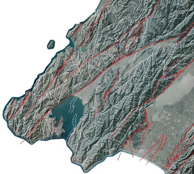
99
built to extend the Wellington tramway system to the suburbs, In the case of brick cores, tests were carried out to assess the
which assisted in the residential expansion of the city and compressive strength of the brick and the mortar, see Figure 6.
facilitated its economic development.
Coring was extended into the ground behind the lining and
The tunnels have some common characteristics: portal structures to investigate the presence and thickness of
backfill or of voids, and the quality of rock behind the portal
They were constructed at the beginning of the last century, walls and lining. CCTV surveys were carried in the cored holes
using broadly similar construction methodology. where considered necessary (e.g. in Northland tunnel).
The tunnel barrels are lined with brick, and in some cases
partly with unreinforced concrete. Geological and Geotechnical Investigations
The portals generally consist of unreinforced or in some Engineering geological mapping was carried out on slopes
cases lightly reinforced concrete gravity walls. associated with the tunnel portals, and other soil and rock
outcrops in the vicinity of the tunnel and portals. The mapping
SEISMIC ASSESSMENT METHODOLOGY provided understanding of the thickness of the overburden soils,
The methodology followed for seismic assessment and design the profile and quality of bedrock, and the presence, orientation
of the strengthening of the tunnels presented in this paper and spatial distribution of rock defects.
generally followed the stages described in the sections below. The engineering geological mapping also assisted in identifying
the areas of uncertainty with respect to the ground and
Desk Study groundwater conditions and enabled more efficient scoping of
necessary geotechnical investigations.
Desk study was an initial and very important part of the
assessment. Desk studies included review of available Geotechnical investigations comprised boreholes, trial pits and
information such as as-built drawings, construction stage machine auger holes, as appropriate. Laboratory uniaxial
photographs, relevant geological and geotechnical information compressive strength tests were carried out on selected rock
and subsequent inspection and maintenance reports. The review samples, to assess the strength of the rock. Downhole
of historical information in particular, including photographs geophysical surveys were carried out in the boreholes,
and newspaper articles of the time, sourced from regional and comprising downhole Acoustic and Optical Televiewer surveys
national libraries, provided some useful insights about the (ATVs and OTVs) in cases where the presence and orientation
construction methods, the quality of the rock mass, and in some of rock defects were critical for the stability of the tunnel, the
cases the failures that occurred during construction. Some portals and associated slopes. The results and interpretation of
historical photographs from the construction of Seatoun tunnel these are discussed in more detail in the Cable Car Tunnels
portals are presented in Figure 3 and Hataitai Bus tunnel in section of this paper.
Figure 4. The Hataitai photograph shows a tunnel collapse
during construction, though its exact location is not known. Engineering Assessment
Investigations Precedent Behaviour of Tunnels in Earthquakes
Site investigations were carried out to inform the seismic An understanding of the precedent behaviour of tunnels in
assessments and consequent design of strengthening measures earthquakes is important in assessing the seismic performance
for the tunnels. These are described in the following sections. of the tunnels. International experience generally shows that
underground structures perform better in earthquakes than
Topographical Surveys surface structures [11]. This appears to be mostly the case when
the tunnels are at substantial depths below the ground surface
Topographical surveys were carried out at the tunnel portals,
and when they are constructed in good geological conditions.
including side and wing walls and associated slopes, or at other
locations critical for the assessment of the tunnels. In some Several studies of tunnel performance during earthquakes have
cases, the topographical surveys, apart from the conventional been published [12,13], and of particular use are reviews of the
ground surveys, included laser scan surveys. The laser scan performance in large earthquakes in Taiwan [14,15]. When
provided 3D models of the portal structures, slopes and tunnel damage to mined sections of tunnels was observed, these were
sections, which were used for structural and stability analyses, indicated to be situations where:
for design of the mitigation measures and the architectural
design of strengthening. Examples of the images obtained from the tunnel is close to the epicentre, or close to the ground
the laser scan are shown in Figure 5. surface, or in large earthquakes, i.e., damage increases as
peak ground acceleration increases;
Structural Investigations the tunnel lining is substandard, due to design not taking
adequate consideration of ground, groundwater or seismic
Inspections of the condition of the tunnel lining and portal and loads, or due to time deterioration;
wing walls were carried out by structural, geotechnical and
tunnel engineers and material specialists, to visually assess the the tunnels are intersected by active faults that rupture;
condition of structural parts of the tunnel barrel and portals. the tunnels are subject to asymmetrical loads in proximity
to slopes or are affected by some form of slope instability.
Core samples of the concrete or brick were obtained at selected
locations of the tunnel barrel lining and portal walls to examine The studies indicate that no or minor damage was observed,
the quality of the materials, the thickness of the structural where peak ground accelerations were up to 0.2g, while
elements and to investigate the presence of reinforcement, when moderate to severe damage could be expected for peak ground
this was not clear from the available drawings. Laboratory accelerations greater than 0.4g to 0.5g, depending also on other
compressive strength tests were carried out on these samples. factors, such as those mentioned above.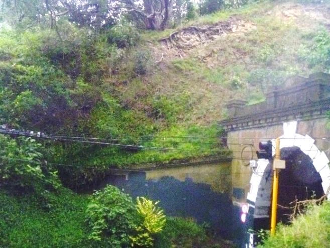
100

           Figure 3: Photographs of the construction of the portals of Seatoun tunnel taken circa 1905 – 1906 [8,9].

 Figure 4: Photographs of the construction of the portals (left) and tunnel section (right) of Hataitai tunnel taken in 1907. The
                               photograph of the tunnel section is following a roof failure [10].

Figure 5: Left: 3D model from the laser scan of the Hataitai tunnel portals, used for architectural design. Right: Cross section at
  the portal of the upper tunnel of the Cable Car tunnels used for stability and structural analysis. The red line depicts ground
   topography captured from the laser scan, combined with topography from the Council Lidar data, depicted by the grey line.

                   Figure 6: Core sample taken from the brick lining (left); cubes of mortar cut from bedding,
                                            shown with capping for testing (right).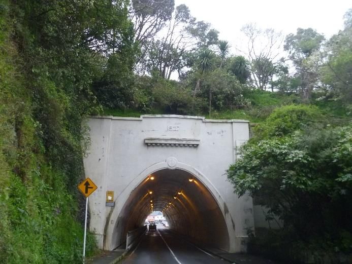
101
The observations from the international literature were in tunnels and on slopes around Wellington. A characteristic
confirmed in the New Zealand context by the damage recorded wedge failure observed on the roof of the unlined Orongorongo
in the railway tunnels affected by the magnitude M7.8 Kaikōura water supply tunnel in Wainuiomata, which is formed in
earthquake of 14 November 2016. The extent of the damage to Wellington Greywacke is shown in Figure 8.
the mined railway tunnels away from the portals was minor,
except when adjacent to slopes, landslides, or fault rupture, and Such wedge failures are generally expected to be localised
was far less than the damage to adjacent sections of above along the length of a tunnel but could load the tunnel lining
ground railway where significant slope and embankment asymmetrically and cause cracking. Due to the highly fractured
failures occurred. The damage in the tunnel lining observed and variable nature of the greywacke bedrock in the Wellington
consisted of minor cracking where adverse combinations of area, it is generally difficult to assess with certainty, without
defects were present and were readily repaired by techniques extensive investigations, the size, shape and location of the
such as installation of rock bolt arrays [16]. However, more wedge failures.
substantial damage was observed in tunnels near slopes and a The likely consequences of such failures on the tunnel lining
tunnel that crossed a rupture section of the Hope Fault. were generally assessed as
Although there were no recorded motions near the tunnels, the
peak ground accelerations in the area are likely to have been of none, to localised minor cracking of the concrete linings;
the order of 0.5g to 0.7g. localised minor to moderate cracking and dislocation of
Observations in New Zealand as well as overseas earthquakes some bricks for tunnels lined with bricks.
indicate that the tunnel portals experienced more damage than Such damage would be expected in large earthquake events and
the underground sections. would be easily repairable.
Ground Motions
The expected performance of different parts of the Wellington
city tunnels under consideration in this paper was assessed in a
range of seismic events, with recurrence intervals of 25, 100,
250, 500 and 1000 years, as well as in a magnitude 7.5
earthquake associated with a characteristic rupture of the
Wellington Fault. The tunnels are located at distances ranging
from 250 m to 7.5 km approximately from the Wellington Fault,
with the Northland and Cable Car tunnels being the closest and
Seatoun tunnel being the furthest away.
Ground motions for the seismic assessment of the tunnels and Figure 7: Wedge failure mechanism from tunnel roof and
their portals were based on NZS 1170.5:2004 [17], assuming a walls [19].
site subsoil Class B or C, depending on the ground conditions
at the location of each tunnel element assessed.
Assessment of the Seismic Performance of the Tunnel Barrel
The tunnel barrel can experience three principal types of
deformation under seismic shaking: axial, curvature and
racking (in rectangular cross-sections), or ovaling (in circular
cross-sections) [11,18].
The axial and curvature strains of the ground are not usually
critical for horizontally or nearly horizontally aligned linear
tunnels [11]. The shear distortion of ground caused by vertically
propagating shear waves is probably the most critical and
predominant mode of seismic motions for most tunnels. It
causes a circular tunnel to oval and a rectangular underground
structure to rack and could lead to cracking of the tunnel lining.
The magnitude and severity of deformation of the tunnel
depends on the elastic parameters of the surrounding ground, Figure 8: Wedge failure mechanism observed on the roof of
the depth of the overburden, the diameter of the tunnel and the Orongorongo water supply tunnel in the Wellington Region.
relative stiffness of the lining and the ground [11].
Assessment of Seismic Behaviour of Portals
More details on the methodology and the results of the tunnel
lining assessments will be presented in the case histories The tunnel portals are more prone to damage under earthquake
discussed in the following sections. The linings of the tunnels loading. The portals and side or wing walls of the tunnels
discussed in this paper were assessed to perform adequately discussed in this paper are generally unreinforced retaining
with minor to moderate damage under large earthquake events, walls (or lightly reinforced in the case of Northland tunnel), see
apart from a section of the middle tunnel of the Wellington Figure 9.
Cable Car, which is in close proximity to a steep slope, has
Local stability of the retaining walls was checked for sliding,
shallow overburden depth and is affected by slope creep
overturning and bearing type failures for the various heights of
movements. This is discussed in more detail in the Cable car the walls, considering the connectivity to the tunnel barrel. A
tunnel section. factor of safety against failure was computed as the ratio of
The effect of failure of a rock wedge (rock block) formed by a resisting forces to the disturbing forces. In addition to the self-
combination of unfavourably oriented rock defects, on the inertia loads, earthquake earth pressure forces were considered
tunnel lining was also examined (see Figure 7). Such types of as acting on a rigid wall [20] as the portal walls and wing walls
failure occur in Wellington Greywacke and have been observed are usually connected to tunnel barrel and founded on rock. The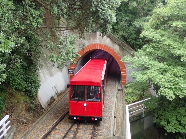
102
inertia forces were considered with sloping locked-in soil at the This approach ensures acceptable performance of the walls, by
retained soil side of the walls. limiting displacements of the walls to acceptable levels in the
different earthquake events, to ensure that the structure does not
collapse, and the road will remain open albeit with some minor
damage of the portal walls. For slopes, small slips that can be
readily cleared were accepted, provided large failures that
would not affect the tunnel structure or close access for long
periods are prevented. This approach was adopted by
Brabhaharan and Saul [21] from the early stages of the
Wellington City Council strategy of assessing and enhancing
the resilience of their road network.
The performance-based design approach adopted has enabled
the development of cost-effective solutions to enhance the
earthquake performance and enabled such strengthening works
to proceed. The performance-based approach to geotechnical
design was incorporated into the Waka Kotahi - New Zealand
Transport Agency Bridge Manual [22] for design of highway
structures in New Zealand [23]. This has now become a
common established approach for the design of retaining walls,
Figure 9: Hataitai Bus tunnel west portal, parapet and wing embankments and slopes in New Zealand.
walls (before the strengthening works).
The strengthening measures of the tunnels were designed for a
Other features of the tunnel portals, such as parapet walls above design life of 100 years. An Importance Level of 2 was adopted
the tunnel portals, were also assessed for their seismic in accordance with the Bridge Manual [22].
behaviour. These features were usually not structurally
connected with the tunnel barrel. General Strengthening Concepts
Methods of strengthening generally adopted for the tunnels
Assessment of Seismic Behaviour of Slopes comprised:
The stability of the slopes associated with the tunnel portals are Ground beams: these were placed above the tunnel arch and
important for both the performance of the tunnel structure, but immediately behind each of the tunnel portal walls and
also for the overall resilience of the route. It is insufficient to parapets and tied to provide support to the portal structure
only stabilise the structural components of a tunnel portal to above the tunnels.
achieve satisfactory performance in a large earthquake if large
landslips on the associated slopes could block the road at the Reinforced concrete buttresses: these were used to
tunnel approaches for a few weeks. In some instances, as for strengthen the portal or wing walls. The buttresses were
example in the Hataitai Bus tunnel, rockfall from the slopes socketed into rock at their bases, using either shallow
above the portals also pose traffic safety issues, see Figure 10. foundations or piles, depending on the ground conditions.
Ground anchors, through the portal and wing walls and the
reinforced concrete elements to tie the structures into rock.
The ground anchors were double corrosion protected by pre-
grouting into high density polyethylene (HDPE) sheaths to
provide a 100-year design life, and their heads were carefully
concealed into the walls and buttresses.
New reinforced concrete beams and buttresses, together with
the ground anchors, are the principal load resisting elements of
the strengthened tunnel portals. These are arranged so that the
load demand on the original, mostly unreinforced or lightly
reinforced but robust walls is significantly reduced, and these
can span between the new elements.
A key feature initially developed for soil nails by Brabhaharan
[24] and adopted for the ground anchors was the adoption of
post-grouting. During post-grouting, the anchors were pressure
grouted using a tube-a-manchette through nodes in a post-grout
Figure 10: Rockfall hazard from slope above the east portal tube grouted-in during the primary grouting. This minimised
of the Hataitai Bus tunnel (rockfall source shown in white). the need for preliminary grouting and re-drilling and enhanced
the bond capacity of the anchors in the variable rock conditions
Therefore, critical slopes associated with the tunnel portals encountered near the tunnels. It also minimised construction
were also assessed, and where necessary, hazards were time and cost.
mitigated as part of the resilience enhancement of the tunnels.
These were generally rock slopes and were assessed Heritage and Architectural Design
considering the rock quality and the orientation and persistence
of defects present. The strengthening works were architecturally designed to
preserve the existing features, minimise the effects on the
DESIGN OF STRENGTHENING MEASURES appearance of the structures and be in line with their heritage
status. More specifically:
Design Philosophy The ground beams were installed and hidden behind the
The design of strengthening measures for the portal walls and parapets of both portal walls, to have no impact on the
wing walls followed a performance-based design approach. aesthetics of the tunnel.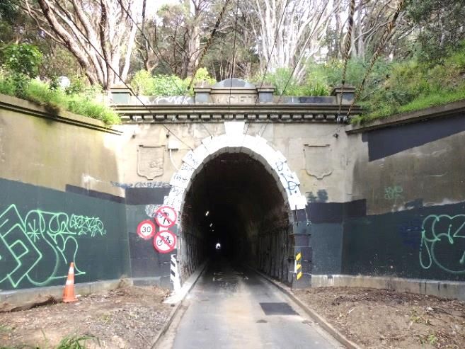
103
The new concrete elements, such as the buttresses, were with time and failed under static conditions, exacerbated by
positioned and detailed to provide an appearance consistent rainfall events. The risk to road users under small, frequent
with the existing features and finish. events was assessed as minor and consisted more of a nuisance
The heads of the rock anchors were concealed and finished and maintenance issue. The risk under severe storm and
flush with the existing surfaces. earthquake events was, however, assessed as high. Rock fall
protection measures were implemented, comprising a high
Plastering was carried out to provide a consistent finish and strength steel wire mesh (nominally 1770 N/mm2), single
painting of all the portals on completion of the works, using twisted into rhomboidal mesh, fixed on the slope with a 3.0 x
colours close to the original concrete to maintain the 3.0 metre pattern of 4-metre-long rock bolts, see Figure 11.
character of the tunnel.
Business Case for Strengthening
Strengthening concepts and design were developed by the
authors, who also managed the implementation of the
strengthening works. Business cases were prepared to
document the resilience benefits including economic analyses
and the assessing the benefit-cost of carrying out the
strengthening works to facilitate funding subsidy for the work
from central government. The cost of strengthening each of the
tunnels was of the order of $1 Million to $2 Million (New
Zealand dollars), and the strengthening had benefit-cost ratios
of the order of 4 to 8.
HATAITAI BUS TUNNEL
Description
Figure 11: Rockfall protection mesh installed above the
The Hataitai Bus tunnel connects the City Centre and the suburb Hataitai end portal. View of the finished portal walls.
of Mt Victoria (west portal) to Hataitai (east portal) and the
eastern suburbs. The tunnel was initially designed for the
NORTHLAND TUNNEL
electric tramcars only. It is single lane, nowadays used by buses
only, with traffic lights at either side controlling the buses
coming from each direction. The tunnel is 310 m long with an Description
arch about 5.25 m high and 4 m wide and is lined with a 450 mm The Northland tunnel was built circa 1927 to provide a tramcar
thick brick lining. The portals at each end comprise mass link to the suburb of Northland (see Figure 13). It is 90 m long,
concrete portal walls and wing walls. The eastern portal is 7.5 m wide and 5.5 m high. It now provides vehicle and
constructed on rock while the western portal is located on fill. pedestrian access along Northland Tunnel Road and connects
Northland to the suburb of Karori.
Seismic Performance Assessment
The tunnel lining comprises an approximately 2.5 m high
A previous seismic assessment of the Hataitai bus tunnel reinforced concrete wall with a reinforced concrete arch on top.
concluded that the tunnel barrel and lining will perform There is a 1 m wide footpath on either side with a steel handrail
adequately in the range of earthquakes discussed in the previous installed on the western side. The tunnel is overlain by
sections, provided that the portals provide confinement to the sandstone rock of Wellington greywacke formation at the
tunnel lining. The stability analysis of the portals and wing northern end and at the southern end is overlain by a thin layer
walls showed that they are marginally stable for the 25-year of sandstone, overlain by fill. A view of the north portal of the
serviceability limit state (SLS) seismic event. Displacements tunnel before the strengthening works is shown in Figure 14.
greater than 100 mm could be expected for earthquake events
larger than the SLS event, and failure by sliding and/or In 1925, following the construction, an inspection was
overturning could be expected for the ultimate limit state (ULS) conducted by the Public Works Department. The inspection
event, with a recurrence interval of 1000 years. concluded that the tunnel was unsafe due to the following
issues:
The strengthening works included ground beams behind the
portal walls to strengthen the slope behind the portal walls and Numerous cracks were observed throughout the tunnel,
retain the parapet walls, and reinforced concrete buttresses in some of which had opened up to 25 mm.
front of the portal and wing walls that were tied back with 6 m The lining did not have a uniform thickness throughout the
to 14 m long rock anchors (see Figure 12). More details about tunnel. The lining was split into 4.3 m lengths but with no
the Hataitai Bus tunnel strengthening works were provided by reinforcement was installed to connect the sections
Arumugam and Brabhaharan [25]. together.
Rockfall hazard was identified on the slopes above the eastern Bars left behind the concrete in the tunnel walls would
portal, causing a maintenance issue and safety risk for the road decay over time and cause the ground to settle.
and tunnel users. The source of the rockfall above the portal is The vibration caused by the trams going through the tunnel
shown in Figure 10. Rockfall was generated by unfavourably could affect the broken concrete, resulting in a risk of
oriented rock defects, forming rock blocks that became loose failure of the side walls.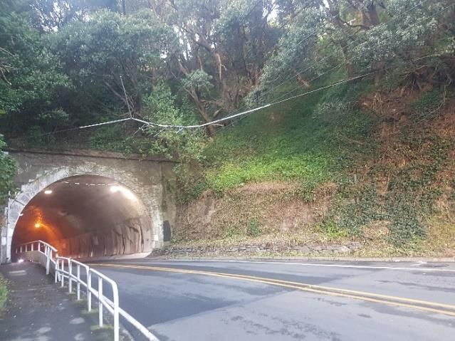
104

                                                                                                      GROUND BEAM

                                                        EXCAVATED AND
                                                        SOCKETED 0.5 M
                                                        INTO BEDROCK

             Figure 12: Typical section of strengthening measures through the portal walls – Hataitai bus tunnel.

Figure 13: Tram passing through the northern portal of the          Figure 14: North portal of Northland tunnel (photograph
    Northland tunnel on inauguration day, 1929 [26].                         taken before the strengthening works).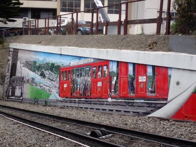
105

              Figure 15: Strengthening of the Northland tunnel immediately after completion of initial construction.

As a result of these issues, the tunnel lining was strengthened       considered, despite the variable ground conditions and the
immediately after construction, using steel sets and an overlay       increased loading associated with the fill materials at the south
of reinforced concrete. The strengthening is understood to have       section.
comprised overlaying the original lining with steel sets (rolled
steel joists new British Standard heavy beam referenced as            It was concluded that strengthening measures were not
NBSHB No 2, 127 mm x 114 mm, 30 kg/m, Figure 15, [27])                necessary for the tunnel barrel. There may be some cracking of
and reinforced concrete of 450 mm thickness. The steel sets           the lining, particularly at the interface between the soil and rock
were located at 1 m centres over the northern 45 m length of the      overburden and along the southern section, but such damage in
tunnel, and at 0.75 m centres over the remaining southern             large earthquakes is expected to be easily repairable. Severe
section.                                                              damage or collapse of the tunnel was assessed as unlikely.

Seismic Performance Assessment of Tunnel Barrel                       Seismic Performance Assessment of Tunnel Portals

Coring investigations through the lining confirmed the                The assessment of the seismic behaviour of the portals
increased thickness of lining. The concrete coring also               concluded that the portal walls and wing walls were marginally
identified voids, which in some cases were up to 0.6 m wide           stable for the 25-year serviceability limit state (SLS) event and
and cracking in the lining. Voids between the lining and the          the 100-year event. The walls could be prone to overturning for
surrounding ground were not common, as the lining was either          the 250-year event but based on the assessed displacements the
in direct contact with the rock or the void was infilled.             damage expected would be easily repairable. Large and
                                                                      unacceptable displacements or failure in sliding and /or
Laboratory testing was carried out on the core samples to             overturning of the portal walls could be expected in the 500-
determine the strength of the lining. The testing confirmed that      year event and the ultimate limit state level (ULS) earthquake
the concrete lining along the southern end of the tunnel,             event or larger (i.e., 1000-year or larger).
constructed in fill, had higher strength (61 - 77 MPa) than the
concrete in the northern end (33 - 46 MPa) constructed in rock.       The northern portal parapet wall was also found to have
It appears that the variability in the ground conditions was          unacceptable behaviour in events larger than the 25-year to 100-
considered when the tunnel was strengthened.                          year ones. Extensive cracking and tilting of the portal walls and
                                                                      parapet could cause a safety hazard for the tunnel users in large
The seismic performance of the tunnel barrel was assessed for         events, while severe damage or collapse of the walls could
the range of earthquake events discussed in the previous              cause closure of the tunnels. Similar conclusions were made for
sections. The cracking and voids in the lining were considered        the wing walls of both tunnel portals.
in the assessment by reducing the effective thickness of the
lining. Due to the variation of the soil profile over the length of   Seismic Performance Assessment of Slopes
tunnel barrel, two different soil profiles overlying the tunnel
barrel were examined: one in sandstone and one in fill. More          The slope above the northern portal consisting of fill was found
details on the results of the assessment were presented by            to be marginally stable in static conditions. More than a metre
Arumugam and Brabhaharan [25].                                        lateral displacement could be expected in earthquake events
                                                                      with recurrence periods larger than 100 years. Failure of this
The assessment of the seismic performance of the tunnel barrel        slope could block access to the tunnel but could be cleared
indicated that it would perform adequately in the seismic events      quickly.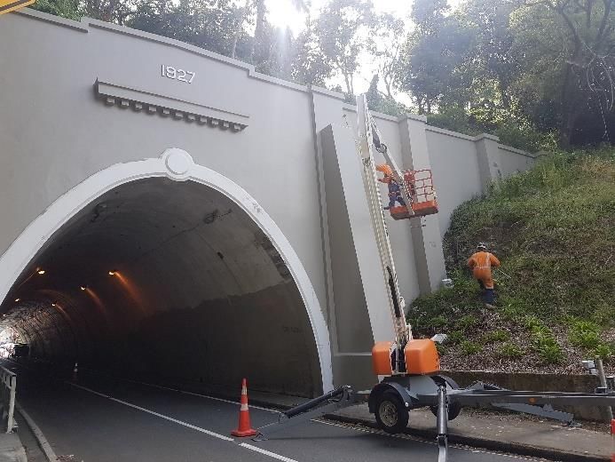
106
The southern portal of the Northland tunnel is constructed in a Reinforced concrete wall buttresses (0.5 m thick by 5.5 m
cut slope, which at the west (left) side of the portal is up to 15 m wide), founded on 600 mm diameter piles socketed 3 m into
high (Figure 16). The slope is excavated in rock, at a steep angle bedrock (typically 3 No piles of 600 mm diameter).
of 70 to 75 degrees. This slope has generally performed Rock anchors typically 8 m long, 32 mm dia. 1030 MPa,
satisfactorily since the construction of the tunnel, without major double corrosion protected bars grouted into rock, to tie
instability or rockfall issues reported, but due to its height and back the portal and wing wall faces.
steepness and the proximity to the tunnel portals, its stability
was included in the assessment. Photographs of the north portal after strengthening are given in
Figure 17, and the strengthening works are illustrated in the
diagrams of Figure 18.
The strengthening adopted for the south portal included (Figure
19):
A ground beam for strengthening of the parapet wall, which
was extended to support the wing wall, and was hidden
behind the portal.
Reinforced concrete overlays to strengthen the existing
buttresses on either side of the tunnel entrance, which was
tied back with rock anchors.
Three reinforced concrete columns to strengthen the wing
wall, tied back with rock anchors.
Additional anchors on the portal and wing wall faces. The
rock anchors were typically 8 m long, 32 mm dia.
1030 MPa, double corrosion protected bars grouted into
rock, and their heads were installed in pockets in concrete
Figure 16: View of the south portal of Northland tunnel. members and concealed with mortar and plastering.
10 m to 15 m high and steep rock slope at the left-hand side A photograph of the strengthened south portal is shown on
of the portal (photograph before the strengthening works). Figure 20. The photographs on Figure 17 and Figure 20
illustrate how the strengthening to enhance resilience has been
The assessment concluded that there were unfavourably achieved without compromising the heritage values of the
oriented defects present on the slope that could cause planar / tunnel portals.
wedge type of failures and rockfall hazard to the users of the
tunnel. These failures would not affect the tunnel. Failures of SEATOUN TUNNEL
sufficient size, enough to block part of or one lane of road were
more likely under a 500-year seismic event. It was considered Description
that these failures could not cause damage to the tunnel, while The Seatoun tunnel (also known previously as Crawford’s
partial blocking of the road could be quickly cleared after a Tunnel) is a 147 m long, vehicle and pedestrian tunnel located
seismic event. As a result, such failures are acceptable from a between Broadway Road in Strathmore and Ferry Street in
resilience perspective. No stabilisation measures were Seatoun, Wellington. The tunnel was constructed in 1906-1907,
considered necessary based on the condition of the slope at the originally to extend the tramline to the suburb of Seatoun.
time of the assessment.
The tunnel provides vital vehicle access through the hill that
Strengthening Measures separates the suburbs of Strathmore and Seatoun. It carries
about 6,500 vehicles a day. The alternate access routes over the
The results of the assessment indicated the need for hills and along the bays are much longer and more vulnerable
strengthening of the portal, parapet and wing walls of the to slope failure and underslips, hence are less resilient and not
Northland tunnel. expected to be available immediately after a major earthquake.
Strengthening concepts were developed and options were The tunnel lining comprises cast in-situ unreinforced concrete
compared to select the most suitable methods. The heritage side walls, about 2.5 m in height, supporting the brick arch. The
value of the tunnel portals was a key consideration. An option tunnel is 8.1 m wide at road level and has a 6.2 m wide
of covering the full face of the tunnel portal and wing walls was carriageway, and a 1.2 m wide footpath raised about 0.6 m
considered to address the extensive cracking, but it was not above the carriageway level.
preferred due to the impact on the heritage features. The
selected concept included discrete strengthening elements Earthquake Performance Assessment
added to the existing structure, with minimal visual impacts.
These options were preferred by the Council Heritage Advisor. A previous assessment of the seismic behaviour of the Seatoun
tunnel concluded that strengthening of the tunnel barrel was not
A resilience-based design approach was adopted for the seismic necessary. The unreinforced concrete portal and wing walls at
strengthening of the tunnel portals, considering functionality both portal ends and the retaining wall on the Strathmore end of
and time for recovery as proposed by Brabhaharan [28]. This the tunnel were found to be vulnerable to failure in moderate to
enabled cost-effective strengthening of the tunnel portals that large earthquake events, i.e., with recurrence periods larger than
provided good seismic resilience. 100 years. Failure of these portal structures could lead to
The strengthening adopted for the north portal comprised: collapse of the tunnel barrel adjacent to the portals. This could
cause access into Seatoun to be closed for several weeks or
Reinforced concrete ground beam hidden behind the portal. longer, as post-earthquake resources are likely to be focussed
The beam was connected to the wing walls with drilled and on the recovery of the city centre and regional access routes.
epoxy bonded tie bars. Strengthening of the tunnel portals was recommended to
enhance the resilience of this route.107
Figure 17: North portal and wing walls after strengthening – Northland tunnel.
Figure 18: General layout of strengthening measures of portal and wing walls at the north portal of the Northland tunnel.
Figure 19: General layout of strengthening measures of portal and wing walls at the south portal of Northland tunnel.108
Rock anchors to tie back the ground beam, buttress overlays
and the retaining wall into stable rock.
The rock anchors were typically 8 m long, 32 mm dia.
1030 MPa, double corrosion protected bars grouted into rock.
The anchors were post-grouted using a tube-a-manchette
system to provide good capacity and minimise the need for pre-
grouting and re-drilling in the variable rock conditions. General
views of the Strathmore portal before and after strengthening
are shown in Figure 22.
WELLINGTON CABLE CAR TUNNELS
Background
The Wellington Cable Car runs from Upland Road in Kelburn
to Lambton Quay, in the Wellington Central Business District.
The total length of the route is 600 m, and it is inclined at a
Figure 20: South portal and wing walls post construction of
grade of 1:5.06.
the strengthening measures – Northland tunnel.
The Cable Car line was constructed between 1898 and 1901.
Strengthening Measures The Upland Estate Company, which opened the former
farmland at Kelburn for settlement, chose the Cable Car as the
The strengthening works comprised (see Figure 21): principal means of access from the city [29]. Τhe viaducts were
Reinforced concrete ground beams hidden behind the portal replaced with the present steel and concrete structures in 1929-
wall to provide lateral support and resist the ground loads 30 and the cars and motive system were completely replaced in
from the slope behind. 1978. The operation passed to municipal ownership in 1948 and
is now managed by Wellington Cable Car Limited, a subsidiary
Reinforced concrete overlays to strengthen the existing of Wellington City Council.
buttresses either side of the portal arch, on both portals.
Reinforced concrete beam to support the retaining wall on
the eastern side of the south portal.
Figure 21: General layout of strengthening measures of Seatoun tunnel portals.
Figure 22: Seatoun tunnel – view of the Strathmore portal, before and after the strengthening works.109
Table 2: The three tunnels of the Cable Car line.
Tunnel Approximate thickness of
From - to Length (m) Portal Designation
Name overburden (m)
Upper East of Salamanca road to Upper tunnel - Upper Portal UU
~90 m 10 - 15
Tunnel Talavera Station Upper tunnel – Lower Portal UL
Middle Talavera Station to Clifton ~103 m Middle tunnel - Upper Portal MU 8 – 14
Tunnel Station – Middle Tunnel – Lower Portal ML
Lower East of SH1 to Lambton ~90 m Lower tunnel - Upper Portal LU Inferred 15 - 20
Tunnel Quay Station Lower tunnel – Lower Portal LL
The Cable Car route is notable for its steep alignment and the
remaining older infrastructure, including the formation, tunnels
and viaducts (Figure 23). Virtually all the other parts above the
formation, including the winding mechanism, are modern.
Figure 25: Plan view of the Cable Car line with the three
tunnels. Location of Terrace and Happy Valley faults in
relation to the Cable Car alignment.
According to the Wellington City District Plan [7], the entire
Figure 23: The Cable Car crossing a viaduct. View from Cable Car Route from Lambton Quay to Upland Road is
Kelburn station. scheduled as a Heritage Area. This Heritage Area incorporates
the carriageway and principal structures of the original
The route has three tunnels which are approximately 90 m to ‘Kelburn Cable Car’, being the three tunnels and three viaducts.
100 m long. The tunnels are horseshoe shaped with a maximum The Heritage Area also includes the three stations at Salamanca,
width of 6.1 m and a height of about 5 m (Figure 24). The lining Talavera, and Clifton Terraces.
is an arch comprising brick and mortar masonry above the
spring line and unreinforced mass concrete walls about 2.2 m
Geology and Seismicity
high below the spring line. The tunnels were constructed by
excavation and blasting. The Cable Car alignment is crossed by two faults, the Happy
Valley Fault, close to Salamanca Road and the Terrace Fault
near the Wellington Urban Motorway (see Figure 25). These
faults do not intersect the three tunnels. Previous reports [30]
suggest that the Terrace fault is a Class II active fault with a
long recurrence interval. Both these faults are mapped as
inactive in the geological map of Wellington [2].
The active Wellington Fault is mapped about 500 m northwest
from the Kelburn station. A characteristic rupture of the Hutt
Valley – Wellington segment of the active Wellington Fault is
estimated likely to give rise to an earthquake of magnitude 7.5,
with a recurrence interval of 880 years (average) [31], giving a
probability of rupture of about 11% in the next 100 years.
Historical Performance of the Cable Car Tunnels
Desk study of all information relevant to the tunnels was carried
Figure 24: Typical cross section of the Cable Car tunnels. out. The important issues identified, relating to the performance
of the tunnels, are:
The characteristics of the tunnels are shown in Table 2. A plan
of the Cable Car line and location of the three tunnels is Cracking was observed in the late 90s along the upper 40 m
included in Figure 25. of the middle tunnel. Strengthening works comprising
shotcrete lining and rock anchors were installed in
November 1999 along this section of the middle tunnel.110
Deformation and cracking were noted in the shotcreted The upper tunnel barrel is generally considered to be of
section of the middle tunnel. Convergence monitoring lower risk, compared to the other two tunnels, due to the
showed ongoing slow-rate movement at this part of the thickness of rock overburden, the good quality of rock mass
middle tunnel. No appreciable deformations, larger than observed in the nearby outcrops and the relatively good
measurement tolerances, were found along the rest of the condition of the tunnel lining and lack of signs of distress.
tunnels. These factors make it less prone to damage under
Significant seepages from the brick lining resulting in earthquake loading.
dissolution and weakening of the outer courses of lime
mortar; seepages were more significant in the upper and the
lower tunnel.
Basic Principles of the Seismic Assessment
Wellington Cable Car Limited wanted to better understand the
condition of the three tunnels along the Wellington Cable Car
line and the need for monitoring and strengthening, with two
key objectives: life safety and seismic performance.
The resilience objectives and performance requirements were
developed based on principles similar to those used for the other
transport tunnels in Wellington city. From an asset management
perspective, it was beneficial to consider the criticality of
strengthening needs for the different tunnels and portal
structures and prioritise and stage any strengthening required.
An initial assessment of the criticality of the different parts of Figure 26: View of upper portal of middle tunnel built near a
the tunnels was carried out, as part of the desk study, to enable south dipping slope.
prioritisation for further investigation and assessment. The
initial assessment was based on the following criteria:
Past performance, such as deformation and cracking of the
tunnel barrel or portal and associated strengthening or
mitigation works.
Vulnerability of the tunnel portal or barrel to failure under
earthquake loading, based on its current condition, overall
characteristics, and considering the general performance of
tunnels in earthquakes and local conditions.
Consequences of failure, such as blockage of the track for a
substantial period or significant effects on adjacent property
and structures.
Potential cost of reinstatement, in case of failure.
The critically of the different tunnel features was initially
assessed as shown below (in order of higher risk and higher
priority): Figure 27: Upper portal of the lower tunnel (LU).
The upper 40 m of the middle tunnel barrel (this is described
in detail in the following sections).
The upper portal of the Middle tunnel (MU), which has a
height, up to 7 m (see Figure 26), including the north (left
hand-) side wall, which is adjacent to Victoria University
buildings uphill from the portal.
The upper portal of the lower tunnel (LU) and south side
wing walls (Figure 27, Figure 28), which are of
considerable height (~6 m at the south side), have a shallow
thickness of overburden and are adjacent to urban
development. Cracking was observed on the portal and side
walls.
The tunnel barrel of the lower tunnel. The overburden of
this tunnel along its entire length is currently unclear,
because of the substantial adjacent urban development and
associated modification of the topography. Rock mass
quality along this tunnel could be poorer than the other Figure 28: South side wall at the upper portal of the lower
tunnels, due to its proximity to the Terrace Fault. The tunnel (LU).
adjacent building structures could also pose a risk.
The other tunnel portals and associated wing walls (UU, Assessment of Seismic Performance
UL, ML and LL), which have substantial heights. Their The Cable Car tunnel portals and wing walls were assessed
collapse could cause damage to part of the tunnel barrel and following the methodology described in the previous sections.
blockage of the line for a significant period requiring costly The key factors in the assessment and conclusions are
reinstatement. Less critical urban development and summarised in the following sections.
structures could be affected.111
Tunnel Portals and Wing Walls cut slope is present at the north (left-hand in Figure 29) side of
the portal.
The most likely modes of failure for the unreinforced concrete
portal walls were found to be sliding and overturning. Minor Evidence of distress of the lining of the upper 40 m length of
cracking could be expected in earthquake shaking with return the Middle tunnel was observed in late 1990’s. This consisted
periods less than 250 years, i.e., with peak ground accelerations of longitudinal cracking of the lining for a length of about 40 m
of the order of 0.15g to 0.3g. Although there has been no direct from the upper portal observed at two locations of the tunnel
record, some of the observed cracking of the portal structures section, at about 11 and 2 o’clock (see Figure 30).
could be attributed to earthquakes with peak ground
accelerations of the order of 0.15g to 0.2g experienced in the
past. Such minor damage would be acceptable and easily
repairable where this was required.
Displacements in excess of 200 mm to 300 mm and associated
damage would be expected in a 500-year event (with peak
ground accelerations of the order of 0.4g to 0.5g), with severe
cracking of the walls and dislodgement of some parts. The walls
could potentially require replacement leading to disruption of
operations for a few months, until repairs and replacement were
carried out. Impact on the Cable Car was considered possible,
potentially causing limited injuries.
Larger displacements and rotation or collapse of walls cannot
be excluded in the 1000-year return period or larger earthquake Figure 29: Upper section of middle tunnel near steep slope.
shaking (for example in a characteristic Wellington fault event)
with peak ground accelerations of the order of 0.5g to 0.7g or
greater.
Tunnel Barrels
The linings of the three tunnels were generally found to be in
good condition, even in areas of extensive seepage. The brick
was rated as hard and the mortar as hard to very hard [32],
based on the measured strengths in excess of 5 MPa.
The tunnel barrels (except the upper part of the middle tunnel)
were analysed using the method proposed by Wang [11].The
brickwork was assumed to behave in a similar fashion to a
concrete lining: the premise being that the brickwork will
behave homogenously and work predominately in compression,
as also proposed by Noble and Kingsland [33].
Exception to the above is the upper 40 m of the middle tunnel. Figure 30: Sketch of the cracking of the lining along the
The Wang [11] approach is inappropriate for this section of the upper 40 m of the Middle tunnel [34].
middle tunnel, which is subject to asymmetrical loading, as will
be described in the next section. The cracking was attributed to asymmetric loading of the tunnel
barrel due to its proximity to the slope and potential occasional
All other tunnel barrels were found to have adequate
slope movements (creep). Based on the analysis carried out at
performance with only minor and easily repairable damage
the time, it was concluded that the available rock wall at the
expected at all levels of earthquakes considered, and therefore
south side of the tunnel could potentially resist the horizontal
no stabilisation measures were considered necessary at this
loading applied by the uphill slope movements, provided there
stage.
were no unfavourably oriented rock defects which could cause
The ongoing convergence monitoring with the tape the rock wall to creep or fail. The slope movement and
extensometer at yearly intervals and regular visual inspections consequent cracking of the tunnel lining had occurred under
of the condition of the lining were recommended so that any static or low to moderate earthquake loading [34].
deterioration or deformation can be detected early to allow
To mitigate this risk, the following stabilisation measures were
proactive intervention, if necessary. Records of monitoring and
installed in 1999 along the upper 40 m length of the tunnel:
inspections provide benchmark for comparison of the lining
performance in case of an earthquake event. Shotcrete lining of a typical thickness of 150 mm. The
It should be noted that only a cursory assessment was possible shotcrete was reinforced by steel wire mesh, and steel bars.
for the lower tunnel, as site investigations were not possible Two rows of rock bolts installed on the north side wall of
given logistical and cost constraints in the built-up location. the tunnel, at heights of 1.5 m to 2.5 m from the ground
surface. The bolts consisted of 6 m long, 32 mm diameter
Assessment of the Upper Part of the Middle Tunnel steel bars, fully grouted into 150 mm diameter holes.
Following the stabilisation works, a convergence monitoring
Background network was installed in the three tunnels in June 2000, and the
The upper 40 m length and the portal of the middle tunnel are deformation of the lining has been monitored since, at yearly
in proximity to a steep slope (Figure 26). The tunnel barrel has intervals and following significant earthquakes.
low overburden, especially at the south side of the tunnel The monitoring results from the upper 40 m strengthened
section, ranging from 2 m to 3 m near the portal and up to about section of the middle tunnel indicated a slow rate movement of
10 m along the 40 m section. A 15 m high, steep, concrete faced the crown towards the south, as shown in Figure 31 [35].112
Although the cumulative displacements measured over the Interpretation of Ground Model and Mechanism of Failure
years are small, of the order of 2 mm in total, the trend of tunnel
movement towards the south continues to persist and is The boreholes drilled showed that the rock mass quality is poor
consistent with the cracking observed prior to 2000. to moderate, with distinctive zones of highly fractured –
shattered and sheared rock.
A few earthquake events have affected the Wellington region
recently, including the magnitude 6.5 Seddon earthquake on The downhole acoustic and optical televiewer geophysical
21 July 2013, the magnitude 6.6 Lake Grasmere earthquake on surveys carried out in the boreholes confirmed the presence of
16 August 2013 and the magnitude 7.8 Kaikōura earthquake on persistent and systematic unfavourably oriented rock defects,
14 November 2016, and these events were associated with i.e., oriented parallel to the slope. Some of the poor-quality rock
modest ground shaking of up to about 0.2g peak ground zones identified are also unfavourably oriented with respect to
accelerations in the Kelburn area. the slope. Two defect sub-sets were identified, one shallow
dipping (40 degrees) that are not expected to
not show significant displacements at the strengthened section daylight on the slope. The combination of these defect sets
of the Middle tunnel. The ground motions measured on rock or forms the potential for a composite failure surface.
stiff soil sites in Wellington during the above earthquakes were
much lower than the peak ground accelerations expected in a The investigations confirmed the initial assessment [34] that
500-year return-period earthquake shaking of 0.4g -0.5g on inferred the potential presence of poor-quality rock mass and
rock or stiff soil, assessed based on NZS1170.5:2004 [17]. unfavourably oriented rock defects, which exacerbate the slope
movements and the effects of asymmetric loading on the tunnel
(see Figure 32).
N
Figure 31: Convergence monitoring profiles V and VI, in the strengthened upper 40 m of the middle tunnel. Convergence
(dashed line) compared to initial (blue line) with movement trend towards the south illustrated (not to scale) [35].
Figure 32: Interpretation of ground model and rock defects affecting the upper 40 m of the Cable Car middle tunnel.You can also read