CLAWAR 2018: 21st International Conference on Climbing and Walking Robots and the Support Technologies for Mobile Machines, Panama City, Panama ...
←
→
Page content transcription
If your browser does not render page correctly, please read the page content below
CLAWAR 2018: 21st International Conference on Climbing and
Walking Robots and the Support Technologies for Mobile Machines,
Panama City, Panama, 10-12 September 2018

 BIO-INSPIRED QUADRUPED ROBOT FOR DETECTION
 CARBON DIOXIDE IN THE AIR

 MARIA CAMILA ROJAS SUÁREZ, SANTIAGO NORIEGA ÁLVAREZ
 El Bosque University, Electronics Engineering Department
 Av. Cra 9 No. 131 A – 02 Bogota, Colombia

 HERNANDO LEÓN-RODRÍGUEZ
 El Bosque University, Electronics Engineering and Bioengineering Department
 Av. Cra 9 No. 131 A – 02 Bogota, Colombia
 Quadruped in comparison with the majority of others animals, it has the ability to access
 to any kind of environment where others living creatures or even humans can’t access.
 Those bio-inspired attributes are taken into this project in order to design and develop a
 quadruped robot with the abilities to move in all kind of directions like ascend or
 descend, avoid obstacles, etc. Combining these skills of the quadruped animals with the
 ability of continuously monitoring the carbon dioxide, the results can be determinants.
 This paper presents the dynamic and kinematics model in addition with the measurement
 scheme of the carbon dioxide index, with the purpose of establish a mechanical sturdy
 device, which can be monitoring an important variable. As a result, we studied the
 movement of real animals, so we can define a suitable bio-mimetic model for our robot.

1. Introduction
 Recently, human has wanted to replicate all kind of movement of animal. This
effort on doing it allowed humans to reproduce robots for certain task instead of
risk their lives. This kind of biomimetic replication can be employed in land
mines task and exploration task. [1] Another important application of these
robots is the incursion in dangerous environments, like contaminated places, or
hostile landmarks. In this order of ideas, we decided that the applicative
background of the robot is the measurement of the concentration of carbon
dioxide, which is an important variable that can generate negative impacts if no
measurement (and regulation) control is applied. Besides, the human beings can
be, easily, exposed to these gases without notice it, with mortal consequences.
Since 90’s researches begin to innovate the whole world with bio-inspired
robot.[2] In 2008 bio-inspired robots became in an important instrument, with
several ability of walking and climbing in all kind of surfaces. [3] [4]
 Nowadays, the majority of quadruped robots have exceptional abilities and
advanced material to be developed. Other approaches have been employed in

 1
2

 their developed of quadruped robots as example parallel mechanism [5], soft
materials [6] self-folding [7], Origami [7], printable robots and so on.
 Nevertheless, this paper presents a device based on quadruped robots with
some basic features and different attributes and applications. See figure 1

 Figure 1: Quadruped robot design and prototype.

2. The Bio inspired quadruped and motion analysis
 In order to accomplish this robot, we stablished how quadruped move and
the algorithm behind this process. The majority of the quadrupeds move in a
mammalian form, like a dog or a horse. Besides this, the spider has 8 limbs, so
we couldn´t use them as a direct source of inspiration. To solve this problem, we
used a mixture of sources of inspiration; we had the quadrupedal animals (their
movement and behavior). On the other hand, we had the anatomy of the spider.
As a result, the anatomy or physic shape of the spider, and the movement of the
quadruped animals in an arachnid way was used.

 Figure 2: Spider’s leg biomechanics
 Initially, it’s important to know that the spider has 7 parts by leg (figure 2).
From the original anatomy of the spider, we suppress some components that we
didn’t need. The reason of this is that we wanted to simplify the whole system.
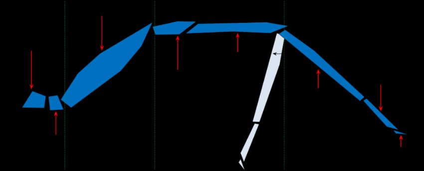
3

Having said this, instead of using the Patella part, we linked the femur and the
tibia by a direct joint. The metatarsus and the tibia were united as a single link or
part. Similarly, we dismiss the tarsus. All of these changes were executed in the
robot, but for the kinematics analysis we took into account the entirely system
for a realistic approach.
 One important aspect is the amplitude that has every part of the spider’s leg.
This means, for example, that the coxa has amplitude of 35 degrees while tibia
has a mobility of 70 degrees. Also, every of the seven components of the limb,
has a different axis of movement; for example, the trochanter has a movement in
X-Y axis, meanwhile the femur in X-Z axis. This kind of association and motion
is explained graphically in the figure 2.

3. Mathematical development
 As we mentioned previously, there are some constraints that we applied in
the anatomic development. We applied these modifications in the mathematical
development and we decided to involve all the possible variables, based on the
following table to produces the most faithful model and prototype.

 Table 1. Degrees and planes of work of each part of the quadruped robot.
 Parts Movements (degrees) Plane
 Coxa 75 Transversal
 Femur 140 Sagittal
 Tibia 40 Sagittal

3.1. Direct Kinematics

 Figure 3: Parameters of the system and coordinate frames of the robot.
 In order to study the direct kinematics of the robot was necessary, at the
beginning; use the joint’s variables of contact limbs and the position and
4

 orientation of the platform. All of this, based on fixed frame represented in
figure 3. Is important to establish that the Ai vectors denote the end points of
contact legs and the Bi vectors represent the connection points of the legs of the
robot to the platform. Taking into account the figure 3 and knowing Ai vectors,
which are the end points of contact legs, we can establish the next expression:

 = + + (1)

 In this expression, and represent the position vector of Bi. In the
same way, we needed to determinate all the parameters of the system in a
graphically mean. In the figure 3 these parameters can be observed.
 One highly important aspect in our robot was the motion and the sequence
that a quadruped robot must follow in order to walk correctly. This item is the
quadruped walking system, which is illustrated in the figure 4.

 Figure 4: Sequence of quadruped walk
 Suppose that the leg 1, 2 and 3 are standing on the ground. According to
relation (1) the location of points Bi versus the fixed coordinate system are
determined and, as direction of x axis of P-coordinate system is direct to 3 1
vector, is possible determine the direction of x-axis unit vector:
 3 1
 = ⟦ 3 1⟧ (2)
 In the same way, we can determinate the vector B3B2
 3 2
 = ⟦ 3 2⟧ (3)
 By having this information, we can determinate the direction of unit vector,
normal to the platform plane. To do this, we first need to implement the cross
product of the two previous vectors:
 = (4)
 In the same way, having the vectors Ex and Ez, is possible to determine the
Ey vector using the same method:
 = (5)
5

 These three vectors are necessary because we can establish the matrix of
the platform versus the fixed coordinate system with the next expression:

 = [ ] (6)
 In order to specify the origin of coordinate system, we can use the equation
of the circle in this way:
 ( 1 − )2 + ( 1 − )2 + ( 1 − )2 = 2 (7)
 ( 2 − )2 + ( 2 − )2 + ( 2 − )2 = 2 (8)
 2 2 2 2
 ( 3 − ) + ( 3 − ) + ( 3 − ) = (9)
 If we solve the previously established equations system, we can determine
the position of the body in the coordinate system.

3.2. Platform velocity
 In order to establish the velocity of the robot’s platform is necessary to
determine the velocity and angular velocity of robot platform by using the
position and velocity of the joint’s variables. In order to specify the direct
kinematics of platform velocity can use (10):
 ⃗⃗⃗⃗⃗⃗⃗ +
 ⃗⃗⃗⃗⃗⃗⃗⃗⃗ ⃗⃗⃗⃗⃗⃗⃗⃗ ⃗⃗⃗⃗⃗⃗ ⃗⃗⃗⃗⃗
 + + = (10)
 In the previous expression, OAi represents a vector that was drawn from the
fix coordinate origin to point “A” from leg No. i. It’s possible to determinate the
relation between velocity of the joint’s variables and platform velocity by
differentiating from (10). The result is (11):
 → → → → → → →
 = × + × + × (11)
 In (11), the first and third element of the equality represents the absolute
angular velocity of femur and tibia, of limb No. i respectively. If we take into
account the symmetry of our robot, (11) this process can be used for the other
three contact legs. By using the fifth element of (11), is possible to establish Vp.
Based on figure 3:
 1→ ˙ → ˙ →
 = 1 . 1 + . 2 (12)
 1→ ˙ → ˙ →
 = 1 . 1 + . 3 (13)
 Regarding to the figure 3:

 = − 2 − 3 → ̇ = ( 2̇ + 3̇ ) (14)
 2

 = − 2 → ̇ = − 2̇ (15)
 2
 In expressions (12) and (13), the first factor in both of them, indicates the
unit vector direct to z-axis of first coordinate frame of limb No. i. The relation
6

 between the unit vectors of different coordinate frames of each leg is
determined in function of the figure 3 as follow:
 ⃗⃗⃗⃗⃗ ̅̅̅̅
 3 = ⃗⃗⃗⃗⃗
 2 (16)
 2 = − sin( 1 ) ⃗⃗⃗⃗ 1 + cos( 1 ) ⃗⃗⃗⃗
 ⃗⃗⃗⃗⃗ 1 (17)
 4 = − ⃗⃗⃗⃗⃗
 ⃗⃗⃗⃗ 3 (18)
 Using the expressions from (12) to (18), we can determine the values of ωi
as follows:
 1→ ˙ → ˙ ˙ → →
 = 1 . 1 − ( 2 + 3 )( − ( 1 ) . 1 + ( 1 ) . 1 ) (19)
 1→ ˙ → ˙ → →
 = 1 . 1 − 2 ( − ( 1 ) . 1
 + ) ( 1 ) . 1
 (20)
 In (19) and (20) the S’s and the C’s, means cosines and sines. In this case,
for mathematical simplicity, we can express all the previous equations as
rotational matrices as follows:
 → 1→
 1
 = (21)
 → 1→
 1
 = (22)
 → 1→
 1
 = (23)
 As we mentioned previously, R represents the rotational matrix of platform
relative to the fix coordinate frame. In this order R1p is the rotation matrix of the
first coordinate frame of limb No.i relative to P-coordinate frame system. This
last rotational matrix is defined as follow:

 cos [( − 1) + ] −sin [( − 1) + ] 0
 3 6 3 6
 = [ sin [( − 1) + ]

 cos [( − 1) + ]

 0] (24)
 3 6 3 6
 0 0 1

3.3. Direct kinematics of non-contact leg
 Direct kinematics of position for a non-contact limb is similar to the direct
kinematics for a serial robot. As shown in Figure 3 can write:
 = + + + (25)
 = (26)
 = 1 (27)
 1
 = (28)
 Based on the previous expressions, PBi can be establishing as follows:

 cos( + ( − 1) )
 6 6
 = [ sin( + ( − 1) ) ] (29)
 6 6
 0
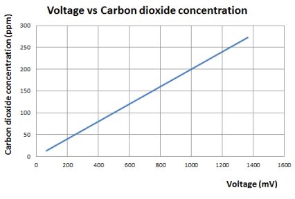
7

 As we did with the contact legs, we wanted to determine the velocity of the
non-contact limbs, so the procedure is similar. We first need to differentiate (25)
as follows:
 → → → → → → → →
 = + × + × + × (30)
 Using Vp and ω, that were derived from (11):
 → ˙ → ˙ → →
 = 1 . 1 + 2 . 2 + (31)
 → ˙ → ˙ → ˙ → →
 = 3 . 3 + 1 . 1 + 2 . 2 + (32)
 From (30) to (32) we can determine the velocity of end points of non-
contact legs; as a result, these values can be specified.

4. Software and Carbon Dioxide Reading Sensor
 The robot control was based in arduino controller and Bluetooth
communication system, sending and receiving routine commands from mobile
device. We used an Arduino-Nano as the controller for the full platform control
and communication system. For motion, 12 servo-actuators were set, 3 for each
leg with a torque of 2.2 kg.cm. These servo-motors are attached directly as a
joint of each link-leg. The supply voltage and current for the robot was a battery
package of 4.8 V and 3000 mA with around power of 7.5 W approx.
 Regarding to the reading of the carbon dioxide index, an embedded circuit
capable of monitoring various types of gases was implemented.

 Figure 5: left: Response profile MQ4, time vs voltage; right: Voltage vs Carbon dioxide.

 The figure 5-left shows the output voltage of the sensor depending of the
gas concentration reading by itself. The result was obtained by adapting the gas
source next to the sensor; meanwhile the gas concentration was increasing.
 Figure 5-right shows the relation of output voltage with the carbon dioxide
concentration; in this way, the characterization of the sensor was adapted
through a linear regression model, obtaining accurate results. An extremely
important aspect to mention is the fact that this issue is still being evaluated and
8

 treated, with the purpose of implementing the sensor that best shapes to the
context and conditioning with the purpose of achieving the best results.

Conclusions
 The project has achieved systematically the design, development and
control of a quadruped walking robot. The mathematical model helped out the
modeling of the motion´s behavior of the robot. The robot has 12 DOF in total, 3
DOF for each leg, controlled by an Arduino Nano via a remote mobile device.
The movement has been analyzed with biomimetic inspirations take from the
spiders. The gas sensor MQ4 was an excellent first approach to the gas sensing
technology because it allowed characterizing the behavior of the gas.
Additionally, these results will serve us as a foundation in future research.

References
1. Zhao Tang, Peng Qi, Jian Dai, (2017) "Mechanism design of a biomimetic
 quadruped robot", Industrial Robot: An International Journal, Vol. 44
 Issue: 4, doi: 10.1108/IR-11-2016-0310
2. S. Shoval, E. Rimon and A. Shapiro, "Design of a spider-like robot for
 motion with quasi-static force constraints," Proceedings 1999 IEEE
 International Conference on Robotics and Automation, Detroit, MI, 1999,
 pp. 1377-1383 vol.2. doi: 10.1109/ROBOT.1999.772553
3. Yi Lu, Keke Zhou, Nijia Ye, Design and kinemics/dynamics analysis of a
 novel climbing robot with tri-planar limbs for remanufacturing, Journal of
 Mechanical, Science and Technology, March 2017, Volume 31, Issue 3, pp
 1427–1436
4. Claudio Semini, HyQ - Design and Development of a Hydraulically
 Actuated Quadruped Robot, A thesis submitted for the degree of Doctor of
 Philosophy (Ph.D.) April 2010.
5. Hongbo Wang, Zhengyan Qi, Guiling Xu, Fengfeng Xi, Guoqing Hu and
 Zhen Huang, Kinematics Analysis and Motion Simulation of a Quadruped
 Walking Robot with Parallel Leg Mechanism, The Open Mechanical
 Engineering Journal, 2010, 4, 77-85
6. Garabini M., Santina C.D., Bianchi M., Catalano M., Grioli G., Bicchi A.
 (2017) Soft Robots that Mimic the Neuromusculoskeletal System. In:
 Ibáñez J., González-Vargas J., Azorín J., Akay M., Pons J. (eds)
 Converging Clinical and Engineering Research on Neurorehabilitation II.
 Biosystems & Biorobotics, vol 15. Springer, Cham.
7. Cagdas D. Onal, Member, IEEE, Michael T. Tolley, Member, IEEE,
 Robert J. Wood, Member, IEEE, and Daniela Rus, Fellow, IEEE; Origami-
 Inspired Printed Robots; IEEE/ASME TRANSACTIONS ON
 MECHATRONICS, VOL. 20, NO. 5, OCTOBER 2015
You can also read