CONCEPT DEVELOPMENT OF A RECLINER MECHANISM FOR A CAR SEAT - ALEJANDRO MORA FONTELLES - DIVA
←
→
Page content transcription
If your browser does not render page correctly, please read the page content below
Concept Development of a Recliner
 Mechanism for a Car Seat

 Alejandro Mora Fontelles

 Master Thesis
 KTH Industrial Engineering and Management
 Production Engineering
Master Thesis :MG2020X

 Concept Development of a Recliner Mechanism for a Car Seat

 Alejandro Mora Fontelles

Approved Company Contact Supervisor
2016-June-27 VA Automotive Daniel Tesfamariam Semere

Abstract
Nowadays, there are more and more regulations regarding the emissions of greenhouse gases. The automotive
sector is directly affected by new standards enacted by the National Highway Traffic Safety Administration
(NHTSA) in America and by European regulations in Europe that are forcing car manufacturers to produce more
efficient cars. Different ways exist to increase the efficiency of a car and thus reduce the 2 emissions. One
known strategy to improve fuel economy in vehicles is by weight reduction. Consequently, car manufacturers are
seeking out new companies that can supply them with lighter car components.

Here is where VA Automotive enters the picture, as a car seat manufacturer that is willing to improve their
product by reducing the weight of its various components. This study deals with the development of a new
recliner design that demonstrates improvements in terms of weight, size and performance compared to the
current solution used at VA Automotive.

A common product development methodology has been developed to reach the final recliner design which went
through the following steps. First of all, a benchmarking technique was adopted to gather as much data as
possible from the competitors’ products. Then, a list of target values for the product specifications was defined
as a guideline for the development of the product. The next step was to generate several concepts of recliner’s
mechanism that were suitable to improve the design from VA Automotive. After that, a Pugh decision matrix
was used to select the best alternative between the concepts generated previously. The optimal concept was
further developed by generating four design alternatives that were analyzed in terms of manufacturing, assembly,
weight and size by using the Lucas DFMA method. Finally some simulations were run for one of the designs in
order to check the structural performance of the mechanism and prove this way that the new recliner design
meets the requirements.

When comparing the new design alternatives with the design from VA Automotive, it was noticed that all the
new designs except one presented a lower manufacturing cost index. Moreover, for all of the alternatives of the
new recliner design, the weight was reduced by more than 56% compared to the recliner used at VA
Automotive. Finally, by means of FEM simulations it was demonstrated that by choosing the right material the
new recliner design was able to meet the structural requirements.

Keywords: recliner, product development process, concept, weight, improvement, design for manufacturing and
assembly (DFMA), benchmarking
NOMENCLATURE

Abbreviations

CAD Computer-Aided Design
FEM Finite Element Modeling
DFA Design for Assembly
DFM Design for Manufacturing
DFMA Design for Manufacturing and Assembly
GHG Greenhouse Gas
CAFÉ Corporate Average Fuel Economy
NHTSA National Highway Traffic Safety Administration
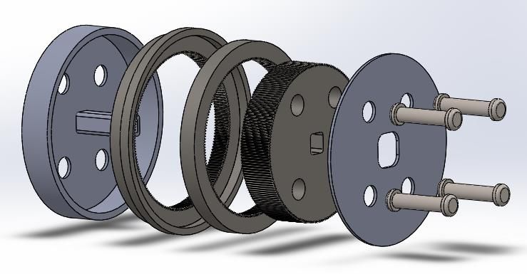
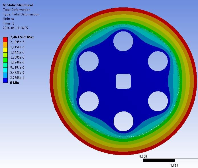
TABLE OF CONTENTS
1 INTRODUCTION .......................................................................................................................................... 1
 1.1 Background............................................................................................................................................ 1
 1.1.1 New trends in automotive sector ....................................................................................................... 1
 1.1.2 Contribution of seats to the global weight of the car ......................................................................... 2
 1.1.3 Car seats components ........................................................................................................................ 3
 1.2 VA Components .................................................................................................................................... 4
 1.3 Purpose of the study .............................................................................................................................. 4
 1.4 Scopes of the study ................................................................................................................................ 5
 1.5 Strategy .................................................................................................................................................. 5
2 THEORY AND METHODLOGY .................................................................................................................. 8
 2.1 Benchmarking........................................................................................................................................ 8
 2.2 Reverse engineering .............................................................................................................................. 8
 2.3 PUGH decision matrix........................................................................................................................... 8
 2.4 Old product development vs new product development ........................................................................ 9
 2.5 Modeling................................................................................................................................................ 9
 2.6 FEM simulation ..................................................................................................................................... 9
 2.7 LUCAS design method ........................................................................................................................ 10
 2.8 Safety in car seats ................................................................................................................................ 10
3 PRODUCT DEVELOPMENT ...................................................................................................................... 12
 3.1 Customer’s needs ................................................................................................................................. 12
 3.2 Design specifications ........................................................................................................................... 13
 3.3 Types of recliner .................................................................................................................................. 14
 3.4 Current product .................................................................................................................................... 15
 3.5 Benchmarking...................................................................................................................................... 16
 3.6 Target specification ............................................................................................................................. 20
 3.7 Concept Generation ............................................................................................................................. 21
 3.8 Concept Selection ................................................................................................................................ 25
 3.9 Concept Development ......................................................................................................................... 27
 3.9.1 Guidelines ....................................................................................................................................... 27
 3.9.2 Push gear recliner ............................................................................................................................ 28
 3.9.3 Design 1 .......................................................................................................................................... 29
 3.9.4 Design 2 .......................................................................................................................................... 32
 3.9.5 Alternative to design 1 .................................................................................................................... 38
 3.9.6 Alternative to design 2 .................................................................................................................... 40
 3.9.7 Planetary gear recliner from VA Automotive ................................................................................. 43
 3.9.8 Comparison between different designs ........................................................................................... 45
 3.10 Simulation............................................................................................................................................ 47
4 DISCUSSIONS ............................................................................................................................................. 51
5 CONCLUSIONS AND RECOMENDATIONS ........................................................................................... 52
6 FUTURE WORK .......................................................................................................................................... 52
7 REFERENCES.............................................................................................................................................. 53
8 APPENDIXES .............................................................................................................................................. 55
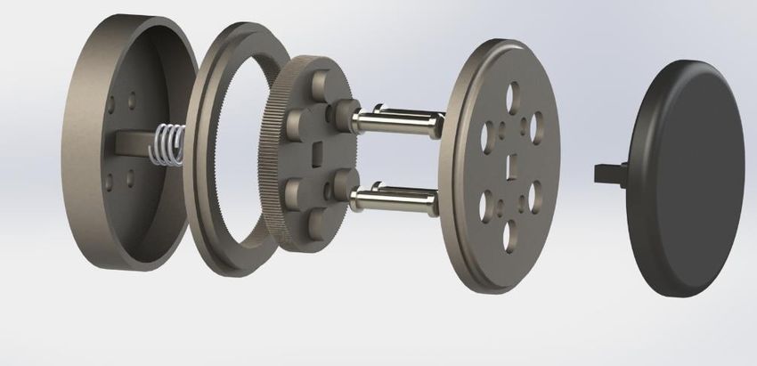
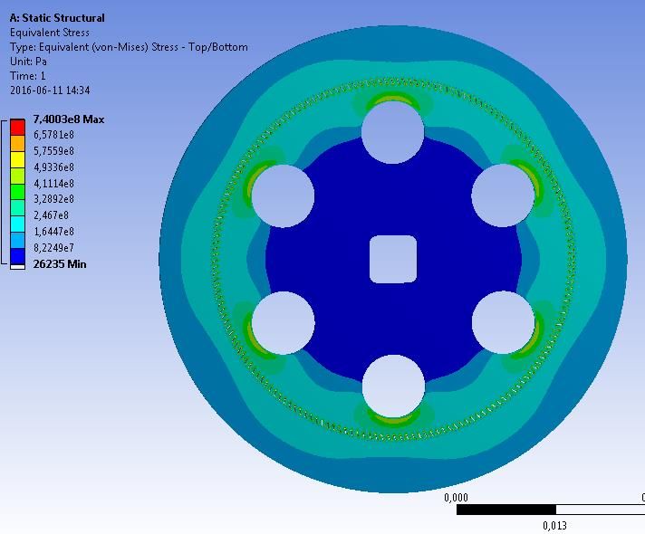
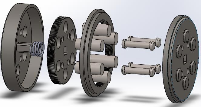
LIST OF FIGURES
Figure 1 : Curb weight and fuel consumption of U.S model year 2005 vehicles .................................................... 1
Figure 2: Mass percentage of Car components (Meszler, German, Mock , & Bandivadekar, 2013) ..................... 2
Figure 3 : Group B components weight (Meszler, German, Mock , & Bandivadekar, 2013) ................................. 2
Figure 4 : Exploted view seat frame assembly (HONDA Original Parts) .............................................................. 3
Figure 5: Weight allocation of an Audi A5 3.0 Tdi (Steinwall & Viippola, 2014) ................................................ 4
Figure 6 : New recliner concept development strategy ........................................................................................... 5
Figure 7 : Customer needs..................................................................................................................................... 12
Figure 8 : Recliner mechanism types .................................................................................................................... 14
Figure 9 : Recliner from VA Automotive ............................................................................................................. 15
Figure 10 : Front seat frames and mechanisms suppliers ranking (Koller, 2013) ................................................. 16
Figure 11 : Faurecia's discontinuous recliner (Koller, 2013) ................................................................................ 17
Figure 12 : Faurecia’s continuous recliner (Koller, 2013) .................................................................................... 17
Figure 13 : Exploded view Faurecia's discontinious recliner ................................................................................ 17
Figure 14 : Exploded view Faurecia's continious recliner (Koller, 2013) ............................................................. 17
Figure 15 : : Magna recliners models i-DISC 4 and i-DISC 3RD ......................................................................... 18
Figure 16 : Exploded view of discontinous recliner assembly .............................................................................. 18
Figure 17 : Recliner Taumel 3000......................................................................................................................... 18
Figure 18 : Recliner Lever 3000 ........................................................................................................................... 18
Figure 19 : Exploded view from a contiuous recliner mechanism ........................................................................ 19
Figure 20 : Toyota Boshoky’s discontinuous recliner ........................................................................................... 19
Figure 21 : Exploded view discontinuous recliner ................................................................................................ 19
Figure 22 :Worm gear recliner .............................................................................................................................. 21
Figure 23 : Envelop worm gear recliner ................................................................................................................ 21
Figure 24 : 4 worm gears recliner ......................................................................................................................... 21
Figure 25 : Top detailed view linear recliner ........................................................................................................ 22
Figure 26 : Linear recliner ..................................................................................................................................... 22
Figure 27 : Push recliner section view "locked" position ...................................................................................... 22
Figure 28 : Push recliner perspective view "locked" position ............................................................................... 22
Figure 29: Push recliner section view "unlocked" position ................................................................................... 23
Figure 30 : Push recliner perspective view "unlocked" position ........................................................................... 23
Figure 31 : 2-sides-brake recliner "locked" position ............................................................................................. 23
Figure 32 : 2-sides-brake recliner "unlocked" position ......................................................................................... 23
Figure 33 : Side view cluster recliner "unlocked" position ................................................................................... 24
Figure 34 : Side view cluster recliner "locked" position ....................................................................................... 24
Figure 35 : Side view bevel gear recliner "unlocked" position ............................................................................. 24
Figure 36 : Side view bevel gear recliner "locked" position ................................................................................. 24
Figure 37 : Criteria weights matrix ....................................................................................................................... 25
Figure 38 : Pugh decision matrix .......................................................................................................................... 26
Figure 39 : Gear diameter vs number of teeth and module ................................................................................... 28
Figure 40 : 180 teeth ring gear .............................................................................................................................. 29
Figure 41 : 180 teeth spur gear .............................................................................................................................. 29
Figure 42 : Design diagram ................................................................................................................................... 30
Figure 43 : Cylindrical box ................................................................................................................................... 30
Figure 44 : Fixed plate .......................................................................................................................................... 30
Figure 45 : Spring ................................................................................................................................................. 31
Figure 46 : Locking cylinder ................................................................................................................................. 31
Figure 47 : Rivet ................................................................................................................................................... 31
Figure 48 : Exploded view recliner design 1 ......................................................................................................... 31
Figure 49 : Recliner design 1 assembly ................................................................................................................ 31
Figure 50 : Fixed ring and rotable ring ................................................................................................................. 32
Figure 51 : Fixed ring gear .................................................................................................................................... 32
Figure 52 : Recliner design 2 assembly ................................................................................................................ 32
Figure 53 : Exploded view recliner design 2 ......................................................................................................... 32
Figure 54 : Spur gear alternative to design 1 ......................................................................................................... 38
Figure 55 : Locking cylinders design 1 ................................................................................................................. 38
Figure 56 : Spur gear design 1 .............................................................................................................................. 38
Figure 57 : Recliner alternative to design 1 assembly ........................................................................................... 38
Figure 58 : Exploded view recliner alternative to design 1 ................................................................................... 38
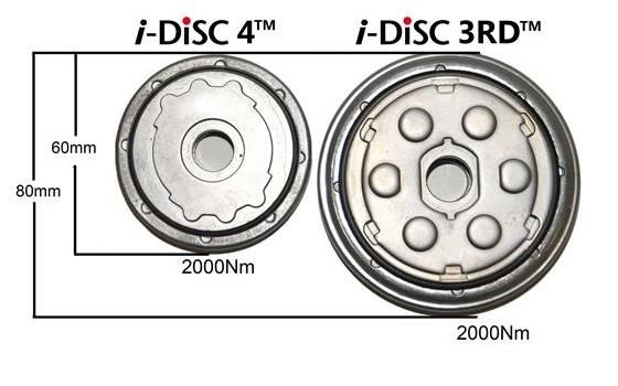
Figure 59 : Merge of ring gear and fixed plate in alternative to design 2 ............................................................. 40
Figure 60 : Merge of cylindrical box and ring gear in alternative to design 2 ...................................................... 40
Figure 61 : Recliner alternative to design 1 assembly ........................................................................................... 41
Figure 62 : Exploded view recliner alternative to design 1 ................................................................................... 41
Figure 63 : Manufacturing cost index vs quantity produced ................................................................................. 47
Figure 64 : Basic processing cost vs quantity produced ........................................................................................ 47
Figure 65 : 2D CAD mode .................................................................................................................................... 48
Figure 66 : mesh parameters ANSYS ................................................................................................................... 48
Figure 67 : mesh generated in ANSYS ................................................................................................................. 49
Figure 68 : Detail view of the mesh generated in ANSYS .................................................................................... 49
Figure 69 : contact selection ANSYS ................................................................................................................... 50
Figure 70 : Equivalent Von-Mises Stress vs gears' thickness ............................................................................... 50

LIST OF TABLES
Table 1 : Design specifications ............................................................................................................................. 13
Table 2 : Components weights of VA Automotive recliner .................................................................................. 15
Table 3: Car seat suppliers ranking (Inc, 2013) .................................................................................................... 16
Table 4 : Data recollected from competitor's products .......................................................................................... 20
Table 5 : Product Specifications............................................................................................................................ 20
Table 6: Lucas's index design 1 ............................................................................................................................ 33
Table 7 : Lucas's index design 2 ........................................................................................................................... 33
Table 8 : Designs comparison ............................................................................................................................... 34
Table 9 : Relative costs design 1 ........................................................................................................................... 35
Table 10: Manufacturing process design 1............................................................................................................ 35
Table 11 : Material costs design 1 ......................................................................................................................... 35
Table 12 : Manufacturing cost index design 1 ...................................................................................................... 36
Table 13 : Relative costs Design 2 ........................................................................................................................ 36
Table 14 : Manufacturing process Design 2 .......................................................................................................... 37
Table 15 : Material cost Design 2 ......................................................................................................................... 37
Table 16 : Manufacturing cost index Design 2 ..................................................................................................... 37
Table 17:Lucas's index alternative to design 1 ...................................................................................................... 39
Table 18 : Relative costs alternative to Design 1 .................................................................................................. 39
Table 19 : Manufacturing proces alternative to design 1 ...................................................................................... 39
Table 20 : Material cost alternative to design 1 .................................................................................................... 40
Table 21 : Manufacturing cost index alternative to design 1 ................................................................................ 40
Table 22: Relative costs alternativeto Design 2 .................................................................................................... 41
Table 23 : Manufacturing process alternative to Design 2 .................................................................................... 42
Table 24 : Material cost alternative to design 2 .................................................................................................... 42
Table 25 : Manufacturing cost index alternative to design 2 ................................................................................ 42
Table 26 : Relative costs VA Automotive recliner ............................................................................................... 43
Table 27 : Manufacturing process VA Automotive recliner ................................................................................. 43
Table 28 : Material cost VA Automotive recliner ................................................................................................. 44
Table 29 : Manufacturing cost index VA Automotive recliner ............................................................................. 44
Table 30 : LUCAS DFA comparison .................................................................................................................... 45
Table 31 : Lucas DFM comparison ....................................................................................................................... 45
Table 32 : Design parameters comparison ............................................................................................................ 46

1 INTRODUCTION
This chapter includes all the information gathered during the first phase of the study which is essential to
understand the work developed throughout this master thesis. New trends in automotive market are analyzed in
order to understand the importance of reducing the car components weight.

1.1 Background

1.1.1 New trends in automotive sector

Since the establishment of NHTSA by the Highway Safety Act in 1970, several standards have been enacted in
order to achieve excellence in motor vehicles. Some of them have been set to regulate the levels of the
Corporate Average Fuel Economy (CAFE) which purpose is to reduce the energy consumption by increasing the
fuel savings of cars and light trucks therefore reducing the greenhouse gases (GHG) emissions. The CAFE
standards are based on a vehicle footprint. That is why for each vehicle’s size there is a specific fuel economy
target. Normally, the fuel economy target for larger vehicle footprint is lower than the one for smaller vehicle
footprint. European legislation has also set new mandatory emissions reduction targets for new cars. For 2021, a
reduction of 40 %, compared to 2007’s average emissions level, is to be achieved. (European Comision, 2016)

 These standards enacted by NHTSA in EEUU and the emission reduction goals set by Europe
legislation are forcing car manufacturers to dramatically improve the fuel efficiency of the car by developing
new technologies or improving the currents one. One known strategy to improve fuel economy in vehicles is by
weight reduction. By reducing the mass of the car, the energy required to move it is lower and therefore the
amount of fuel consumed per km is also lower. Generally it is possible to apply a rule of thumb to estimate the
percentage of reduction of fuel consumed by a car when its weight is reduced as illustrated by figure 1. For a
10% reduction in vehicle weight, the fuel consumption is reduced by 5%-7%. (Cheah, 2010). Since a common
car is compound by several components, it is possible to decrease the overall weight of the vehicle by lowering
the mass of each individual component. It is significant to be aware that decreasing the mass of only one
component will not have a high impact on the overall weight reduction and therefore on the fuel consumed.
Nevertheless, if each individual component’s weight is reduced, due to a cascade effect, the improvement of the
efficiency will be much more noticeable. For instance, by reducing the mass of the chassis and some other
components as seats and main floor trim, it is possible to use an engine with less power and thus reduce the fuel
consumed while maintaining the same ratio power/weight.

 Figure 1 : Curb weight and fuel consumption of U.S model year 2005 vehicles

 1
1.1.2 Contribution of seats to the global weight of the car

 Once the need of decreasing the car weight has been identified, it is then important to understand how
the different components of a car contribute to the vehicle total weight. As it can be seen on the chart below
(Figure 2) the body system Group B, which includes: seats, main floor trim, sun visors, front and rear LH & RH
door trim panel and other interior components, represent generally 14% of the overall weight of a car.

 Figure 2: Mass percentage of Car components (Meszler, German, Mock , & Bandivadekar, 2013)

It is then the third heaviest group of components of a common car where the first one is the frame and mounting
system and the second one is the suspension system. For this reason it is strategic and reasonable to invest in the
development of new designs of these components.

 Group B components weight

 12% Fron Drivers
 Seat
 Front Passenger
 10%
 Seat
 Rear 60% Seat
 12%
 58%
 Rear 40% Seat
 8%
 Others

 Figure 3 : Group B components weight (Meszler, German, Mock , & Bandivadekar, 2013)

 2
The figure 3 illustrates more in details the mass distribution between the different components within the Body
System (Group B). It can be appreciated that seats represent 40%-50% of the total mass of the interior
components of the car that, as stated before, represents the 14% of the overall weight of the vehicle. Therefore
the optimization of seat designs regarding their weight is a key critical success factor for car seat manufacturers
to maintain their competitiveness in the market

1.1.3 Car seats components

 Over the years new car seat designs have been in continuous development with the goal of increasing
the comfort and the safety of drivers and passengers. At the beginning, seats were simple and compound of few
elements. Nowadays, a common car seat assembly is composed of more than hundred different parts. Moreover,
as explained before, the new standards established with the aim of decreasing the emissions of green gas are
forcing car manufactures to produce more efficient cars. Therefore it is a substantial concern for car
manufacturers to design new seats having more components, a better performance than the previous designs and,
at the same time, being lighter.

The seat frame and the adjusting mechanism represent the main parts of a car seat when talking about weight
contribution and safety. That is why companies focus on these parts when they look for an improvement of the
seat safety or when they seek to reduce the overall weight. In today’s market, the full adjusting mechanism is
referred as the “Eight ways”. New generation seats present in total four different mechanisms to adjust the seat
frame to different positions. Furthermore, each of these mechanisms allows the movement in two different ways
bringing in total the eight ways. The recliner adjusts the angle between the backrest and the seat cushion. The
seat tracks allow the distance adjustment between the seat and the steering wheel. Two more mechanism allows
the adjustment of the height of the seat and the angle between the floor and the seat cushion. The figure 5
illustrates an exploded view of a common car seat frame.

 Figure 4 : Exploted view seat frame assembly (HONDA Original Parts)

 3
Figure 5: Weight allocation of an Audi A5 3.0 Tdi (Steinwall & Viippola, 2014)

The figure 5 shows an example of weight allocation in an Audi A5. As it can be seen, seat adjusters do not
represent a high percentage of seat total weight, however the same adjusting mechanism, if it has been design for
that, can be used for all the seats of the car. That means that, as an example, a 500 g reduction in the recliner
mechanism results in a 2kg reduction of the whole car weight (in the case of four seats car).

1.2 VA Components

 The present work has been carried out with the collaboration of VA components, company member of
VA Automotive Group. This group of companies offers the vehicle and engineering industries complete,
innovative and cost- effective solutions that include everything from tools and production equipment, to finished
components. Previously known as Läreda Mekan, VA components is responsible of developing and
manufacturing complex products for the vehicle industry as car seats, airbags and child seats. Since they joined
VA Automotive they have been changing their business strategy by implementing new designs to face the new
growing automotive challenges and meet the new C02 emissions requirements from car manufacturers for the
coming years. In order to reduce the weight of the seats manufactured at VA Components, the design of the
different adjusters has been changed. Therefore there is a new design for the height adjuster, the length adjuster
and for the seat cushion tilt adjuster. Only one adjusting mechanism has not been yet redesign, the recliner.

1.3 Purpose of the study

 The main goal of the thesis is to redesign the recliner mechanism with the objective of obtaining a new
design that is lighter than the current one. However, the mass is not the only parameter to take into account.
Since the margin of profits in car manufacturers is really tight, it is extremely tight, it is fundamental to avoid
high production costs. Furthermore, VA automotive is looking for a new design that can compete with the
competitors’ current products. That is why product innovation plays a key role while designing the new recliner.
The purpose of this thesis is to bring new ideas coming from an external and creative perspective.

 4
1.4 Scopes of the study Since this thesis focuses on the development of a product, which can take more than years in today’s large companies, it is essential to define a frame of work in order to avoid too large and meaningless scope for the present thesis. These delimitations are: The thesis focus on the conceptual design phase of the product development Some assumptions have been done through the development process The thesis does not include complete simulations due to limitations regarding the software license The thesis does not include a final detailed design It does not include a prototype It does not include a physical test 1.5 Strategy In this study a generic product development (Kamrani, 2010) process has been followed to design the new recliner mechanism. As it has been discussed previously when defining the scope of the thesis, not all of the stages of the product development have been completed. The figure below (Figure 6) indicates the steps that were developed throughout this thesis. Figure 6 : New recliner concept development strategy 5
A short description of each phase can be found below:

Needs recognition

The product development process starts by identifying the needs. This critical phase has been carried out during
the first visit to VA Automotive where as much information as possible been gathered after talking with the
engineers. The result from this part of the process is a list with all the customers’ needs that will drive the design
throughout the process.

Establishing design specifications

In this step the needs are translated into technical requirements by defining target values. It represents one of the
most significant and intricate phase of the product development process. It is common to use the benchmarking
methodology to compare the product specifications from the competitors’ products and to find in this way an
opportunity to improve the product performance in comparison with other products in the market and thus to
increase its customer value.

Concepts generation

After having defined all the specification that the new product should fulfil it is the moment to start generating
possible solutions to the problem that can these product specifications. The new concepts can be inspired by
other products in the market, patents, books, imagination and/or other similar mechanical problems. The result
from this phase of the development process is a set of sketches hand-drawn with a description that helps the
reader to understand the concept idea.

Concept selection

The concept selection represents the step where all the ideas generated before are compared through a multi
criteria analysis to obtain the optimal solution. The criteria needs to be chosen carefully since it will determine
which concept is going to be further developed and therefore it will affect straightaway the product development
process result.

Concept development

Once one of the concepts has been selected, the next step is to develop the design for the different product
specifications to be determined and compared to the target values. It is essential to know that a given concept or
idea can have different design alternatives. Because of that, in this step of the product development process some
different designs are generated and compared between each other with the goal of obtaining the best design for
the chosen concept.

 6
Simulations

In the final step some simulations have been conducted to check the mechanical performance of the design
developed and to be able in this way to verify if it meets the safety requirements. Moreover, a parametric
simulation has been developed with the aim of understanding how the different design parameters affect the final
performance of the recliner.

In a full product development project the concept development phase is followed by a detailed design which
allows a better analysis of the solution in terms of manufacturing analysis and testing.

 7
2 THEORY AND METHODLOGY
In this chapter all the information regarding the theories and methodologies used during this work are explained
with the aim of understanding the reasons of using these tools and to know how they have contributed to the
achievement of the proposed goals.

2.1 Benchmarking
 When designing a new product it is fundamental to know the requirements that must be met. One method
used by more and more companies is benchmarking. It consists in picking the best products from others
successful companies of the market and analyzing them in order to obtain performance goals. Benchmarking has
been rated very favorably by the manufacturing industries (Kumar & Chandra, 2001). Wheelwright and Clark
(1992) found that intense international competition, fragmented demanding markets and diverse and rapidly
changing technologies were three critical characteristics driving the product development process in all
manufacturing environments. Due to the high number of car manufactures existing around the world and the
continuous improvement in technologies in the automotive market, car seat manufacturers need to improve
continuously their products in order to remain competitive. Good practices in benchmarking allow companies to
develop products that meet better the customer needs and that can race at the highest competitive level.

2.2 Reverse engineering

 In high competitive markets, companies are not willing to share important information from their
products in order to avoid competitors to copy them and this way they maintain their competitiveness. Reverse
engineering is a method used to extract the knowledge from other companies by analyzing their products (Eilam,
2005). For instance, if a company wants to develop a new solution to solve a given problem but in the early steps
they do not know how to proceed, a possible solution is to analyze the solution that a competitor has already
developed and try to understand it. In that way it is possible to get some ideas from other companies’ solutions
and evaluate the level of complexity of the problem. In this work, the use of reverse engineering may stand as a
highly useful tool due to the lack of expertise and knowledge of the student in this engineering field. One of the
major sources that allows an simple way to practice reverse engineering is the patents database. Indeed, thanks to
the amount of patents available via reliable sources on the internet it is possible to gather a large amount of
information regarding the products functioning, assemblies’ types and products evolution over the years.

2.3 PUGH decision matrix

 Product development process includes most of the time a concept generation phase which aim is to
generate a list of possible solutions that can solve a given problem and to compare them between each other.
This list often represents the result of discarding the unviable solutions after brainstorming. The next step after
generating concepts is to select the most suitable one among them. It exist several methodologies and strategies
to proceed during this phase.

For this thesis, Pugh method has been used for the concept selection phase. First, it is necessary to define some
criteria that often represent all the customer values or at least a part of them. Once all the criteria are determined,
they need to be weighted in order to set the relevance of each one of them. The weight can be obtained by
comparing each criterion with the others through a comparison matrix. Consequently, the different concepts are
compared to the current solution. For each criterion, if a concept represents an improvement it obtains a positive
point. If the concept is less efficient than the current design, it obtains a negative point and if both are equal for a
given criteria, it does not obtain nor positive nor negative points. At the end, the solution with the highest points
represents in many cases the best solution.

Even if this method can help to choose the best alternative between the concepts generated, there are other
methods that can be used to perform a deeper analyze and thus obtain more accurate results. One of these
methods is the Analytical Hierarchical Process (AHP) which allows a more detailed comparison of different
compared to the Pugh decision matrix. (Haskovec, Krehl, Niemi, & Seid, 2016)

2.4 Old product development vs new product development

 Encouraged by the development of new technologies and especially by the quick improvement of
computers, the strategy followed by companies to develop new products has changed. Before, to develop a new
product a common strategy was to find a solution, design it, build a prototype and then test it to know if the
solution founded met the requirements. That is the way to proceed in VA Automotive where the design engineer
develops a new concept which is then prototyped and tested. Nowadays, more and more companies take
advantage of computer capacity when designing a new product to save time and money. Indeed, since building a
prototype, test it and repeat this process until obtaining a good solution is time consuming and increase the
product development cost, by using FEM simulation designers can get an overall idea whether the design is
satisfying or in the early stages of the design phase.

2.5 Modeling

 Nowadays almost all the companies performing product development activities use some of the existing
computer software (CATIA, SolidWorks, Solid Edge…) during the design process. Computer-aided design
allows engineers to develop portable designs with high accuracy. It is also possible to create 3D models from 2d
drawings in a fast way. Another advantage of modeling is the possibility of designing with standards. Moreover
the drawings files can be shared in quickly and easily in a standardized manner. Some of the disadvantages of
using CAD can be the cost of purchasing the modeling software, the training required to use it and finally the
possibility of losing drawings due to computer misfortunes. However, nowadays it is common for engineers to
learn how to use at least one of the CAD software during their academic education.
 In this master thesis SolidWorks have been used as main software for the design of the recliner concepts
and for the generation of the drawings.

2.6 FEM simulation

 Previously it has been explained why the use of simulations can decrease the cost of developing a product
and at the same increase the efficiency by avoiding the long and costly process of building prototypes and testing
them until a good solution is found. To develop the new recliner mechanism the FEM software, ANSYS, have
been used. The simulations of the concept design will give an idea of how good is the design and check at the
same time if it meets the requirements.

 9
2.7 LUCAS design method

The LUCAS design method developed in 1980’s (Chan & Salustri, 2005), can be used when designing a new
product if the assembly process and the manufacturing cost are to be taken into account during the early phases
of the product development process. Some methods exist to design a product for both manufacturing and
assembly. Some of them are: the Boothroyd-Dewhurst DFA method, the Hitachi assembly evaluation method,
the Fujitsu productivity evaluation system and finally the LUCAS method. Not all of them include both
manufacturing and assembly analysis however the LUCAS method, used in this work, includes both types of
analysis.

Design for assembly

The Lucas’s design for assembly is carried out in three sequential steps. The first one is the functional analysis
where the components of the assembly are dived into two groups. The group A, includes all the pieces that are
primordial for the performance of the product. The group B, represents the components that perform only
secondary functions. The efficiency of the design is measured as:

 Design efficiency= 100 x Essential number of components / Total number of components

The next step is the feeding analysis where issues regarding the handling of components are evaluated. The
feeding ratio is calculated by dividing the feeding index and the essential number of components. The feeding
index varies depending on the size, weight, handling difficulties and orientation of the component.
Finally, fitting issues as gripping, insertion and fixing analysis are measured through the fitting analysis. The
way to calculate the fitting ratio is similar to the feeding ratio, it is just necessary to change the feeding index by
the fitting index which is obtain from the LUCAS tables. The fitting index is based on its required fixturing,
resistance, force to insertion and restricted vision during the assembly.

Design for manufacturing

 Lucas DFM method can be used to compare different designs in terms of manufacturing cost. It is
essential to know that the results obtained after the analysis does not show the real manufacturing cost of the
product. It measures only a manufacturing cost index which can be used to compare different design between
them. The manufacturing index cost is based in two main parameters: the material cost and the manufacturing
process cost. Moreover, the value of the process cost will depend on the geometry of the component, the
tolerances needed, the manufacturing process chosen and the production volume. The exact way to calculate
each parameter will be explained later on in the Product Development section.

2.8 Safety in car seats

 Since this master thesis deals with the development of a new recliner concept for a car seat it is important
to understand which is the effect that this one has in the seat’s safety. As the recliner is responsible of connecting
the backrest with the seat frame, it represents a critical part when talking about seat’s robustness and thus safety.
All recliner mechanisms must pass some tests before using them in any seat, which results need to meet the
requirements set by regulations in the automotive sector.

 10
In this work only one type of test is going to be done through simulations in FEM software. Different torque
values are going to be applied to the recliner with the goal of checking its stiffness. The test simulates a frontal
impact where the passenger seated behind the driver moves forwards generating a force in the back rest and thus
a torque in the pivot point between the seat frame and backrest that is, the recliner. It is not necessary to simulate
a rear crash not either a side impact because in both case the stress generated in the recliner would be lower than
the one generated in a frontal accident due to the lower car velocities compared to the frontal crash.

 11
3 PRODUCT DEVELOPMENT
This chapter gathers all the work carried out to develop the recliner concept. All the steps from the product
development process such as needs identification, design specification, concept generation and concept selection
are explained in detail. It includes also an exhaustive analysis from the solutions obtained and the results from
the simulations ran with the FEM software ANSYS.

3.1 Customer’s needs

 The first step in a product development process is to identify the customer’s needs. It is extremely
important to obtain a detailed list of needs before launching the development process. Customer needs can be
defined by collecting information about the requirements that the product must fulfil. The customer demand list
will be the basis on which all the product development process will focus. A product which does not meet the
requirements defined will not be sellable in the market and therefore a large amount of money, spent to for the
development process, will be wasted. In some products it is possible the identification of more than one
customer. It is the case of the product that is going to be developed through this thesis, the recliner. On the one
hand a potential customer may be a company that is interested in buying a recliner mechanism as it could be a
car manufacturer; on the other hand an internal customer, the manufacturing plant, should also be taken into
consideration for the needs analysis.

The requirements requested by car manufacturers include also the demands of end customers, that means car
drivers and passengers. The main function of a recliner is to allow the adjustment to multiple position of the
angle between the seat back and the seat cushion. Nevertheless several parameters determine whether the
recliner mechanism is efficient or not. A list with the different requirements for both customers is shown in the
table below (Figure 8)

 End customer (car manufacturer + drivers +passengers) Internal customer (manufacturing plant)
 No noise Lower manufacturing cost
 Adjust the seat back to multiple positions Reduce complexity
 Adjust smoothly (continuous/discontinuous) Longer life of the product
 Adjust with little force Minimize #of assembly operations
 Ratio of adjustment Easy to assemble
 Durable - strength Innovation (in order to sell it)
 Compact size Connection between recliners
 Light weight Include folding mechanism
 Robust
 Low product cost
 Requires less maintenance

 Figure 7 : Customer needs

For car drivers and passengers it is essential that, when adjusting the backrest position, no uncomfortable noise is
produced by the mechanism. Moreover, it is also important that the adjustment can be executed smoothly and
with little force. That means that the force to actuate the mechanism is not too high. Regarding the movement of
the backrest, if the recliner is continuous it offers a smoother adjustment than the discontinuous recliner. The
ratio of the adjustment represents, in a continuous recliner, the variation in the angle between the backrest and
the seat cushion when the user turns 360º the handle. Another requirement established by car regulations is the
strength supported by the recliner. Indeed, since the recliner is a key element during a car accident, the
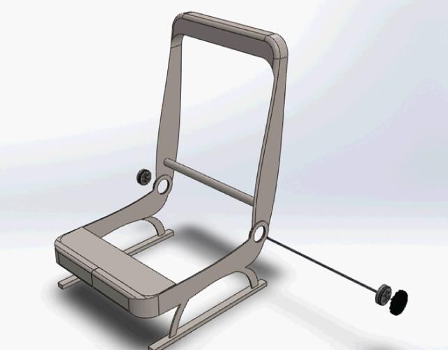
performance of this device is controlled through different tests as stated before. Furthermore, as it has been
mentioned before, the weight is an important issue in the automotive market due to the regulations enacted by
the governments to reduce the greenhouse gas. The size of the product can be in some way related to the weight
since a more compact design reduces the amount of material used. Another parameter that must be taken into
account is the cost of the product. With the technologies existing nowadays it is possible to easily design a
recliner that can fulfil all the requirements shown in the table above nevertheless the challenge is to produce it at
a low cost. Finally the robustness of the recliner and the maintenance required are also essential parameters to be
considered during the design process.

The internal customer, as it has been said before, represents the manufacturing plant where the recliner is going
to be manufactured. Some of the requirements desired by the recliner manufacturer, for instance the
manufacturing cost, are directly influenced by the end customer. In fact, since the margin of benefits can be
calculated, roughly, by the difference between the price of the product and the manufacturing cost, reducing as
much as possible the latter one is one of the main goal of the manufacturer. Other parameters such as the number
of assembly operations, the ease of assembly and the complexity of the design are also directly related to the
final cost of the product. When talking about selling the product, the new design needs to be innovative. Copying
the design that competitors are using is not a useful strategy when looking to sell the product for the reason that
customers will not willing to switch from one supplier to another if there is no an important cost reduction or
some innovation that add value to the product. At the end, the product life, the connection between the recliners
on both sides of the seat and the possibility of including a folding mechanism are requirements that increase the
product’s value and therefore the chance to sell it.

3.2 Design specifications

Once the customer needs has been identified, the next step is to define some metric that will be used as
specifications for the design. Each of these metric will be weighted depending on the importance. The table
below (Table1) shows the five metrics selected for the design of the recliner.

 Table 1 : Design specifications

 Metric No. Metric Unit
 1 Range of rotation º
 2 Torque supported Nm
 3 Diameter mm
 4 Weight g

The first metric, the range of rotation, represents the amount of rotation allowed measured in degrees. The
second one is the torqued supported by the recliner that determines whether the device is providing safety during
a car accident or not. The diameter has been taken into account as a metric since it influences the size of the
recliner. The metric number four is the weight and it will represent the most important one.

 13
3.3 Types of recliner

 Before starting the analysis of the current products that exist already in the market it is useful to check the
different design that exists already for the recliner mechanism by looking for patents. The main goal of this is to
get examples of ideas that have been proposed over the years to solve the problem of adjusting the angle between
the back cushion and the backrest and use them in the development of the new design.

 Figure 8 : Recliner mechanism types

After having checked a great number of patents, the different recliner mechanisms that already exist can be
classified in two main groups: continuous and discontinuous. The first one includes all type of recliners where
the tilting adjustment sensitivity depends on the ratio given by the mechanism. The second one represents those
recliners which mechanism is formed by two main components that need to be disassembly in order to allow the
rotation. Within the continuous recliners group there are the round and linear recliners. For the discontinuous
recliner group it exits only disc recliners which mechanisms are often similar however existing different
configurations. As continuous round recliners it is possible to find mechanisms with planetary gears
configuration or with eccentric one. Concerning linear recliners, it exits two types, the ones that use a worm
gear to transmit the movement and the ones that use a configuration of bars and bolts screws.

Continuous recliner works generally in the same way. An “input” gear rotates by applying a torque to the handle
of the recliner. This movement causes the rotation of an “output” gear which amount of rotation is determined by
the mechanism design ratio. Worm gears, planetary gears and bolts screws offer high ration transmission which
is extremely important to get a smooth adjustment of the backrest.

Unlike the continuous recliner, the discontinuous recliner does not work by transmitting the rotation from one
gear to the other. To the other way around, the gears are used to avoid the rotation. Almost all discontinuous
recliners use the same mechanism: a ring gear having a high number of teeth and some pawls adapted to lock the
ring gear when the recliner is in “locked” position. In these recliner mechanisms, the torque applied by the user
serves to move the pawls and unlock the ring gear allowing the rotation of the backrest.

 14
You can also read