DEVASTATION TOLERANCE DESIGN OF THE WING SPAR OF A TRANSPORT AIRCRAFT
←
→
Page content transcription
If your browser does not render page correctly, please read the page content below
Vol-7 Issue-1 2021                                                                         IJARIIE-ISSN(O)-2395-4396

 DEVASTATION TOLERANCE DESIGN
 OF THE WING SPAR OF A TRANSPORT
            AIRCRAFT
    Mr. Manjunath Kambar1, Prof. Anand Mattikalli2, Prof. Basavaraj Karoshi3, Prof. Santosh
                                        Malipatil4
        1
        M Tech Student, Department of mechanical Engineering, MMEC Belagavi, Karnataka, India
    2
      Assistant Professor, Department of mechanical Engineering, MMEC Belagavi, Karnataka, India
      3
        Assistant Professor, Department of mechanical Engineering, VSMIT Nipani, Karnataka, India
    4
      Assistant Professor, Department of mechanical Engineering, MMEC Belagavi, Karnataka, India

                                                    ABSTRACT
 In a transport aircraft there are normally two competes to take the twisting burdens. The fundamental fight takes a
 significant bit of this twisting second. It is the major basic auxiliary components in a vehicle wing.
 Most assistance auxiliary disappointments in airframes are because of exhaustion breaks. Weakness splitting can't
 be voided yet can be endured by reasonable harm resilience plan. In enormous vehicle wings the principle fight is
 an indispensably machined segment which gets precisely affixed to the skin and ribs. The mechanical affixing
 prompts serious pressure fixation at a couple of clasp gaps. Under help stacking a weakness break can start from
 the most extreme pressure concentrator. This weariness break will develop under assistance stacking first in the
 spine and afterward develop into the fight web. This break development can prompt calamitous disappointment if
 not identified during administration and fixed. This undertaking work will examine substitute basic plan of the
 fundamental fight to make it harm lenient. The fight development will be in two of discrete parts with one more
 middle of the road spine and at a stature of 1/third from the base rib. These two pieces can be precisely secured.
 In case of weariness breaking the base rib and web may flop however the top rib, web and the middle of the road
 spine will stay unblemished and can be intended to convey the necessary plan limit load.
 A limited component displaying and examination approach will be utilized to contemplate the two kinds of fight
 narrowing and approve the harm resilience plan idea.
 Catchphrases

 Keyword: Transport airplane, Wing, Damage resilience plan, Finite component examination, Fatigue split,
 Service factor etc…

1. INTRODUCTION

 Air1craft are vehicles which can fly by being upheld by the air, or in general, the atmosphere of a planet. An
 airplane counters the power of gravity by utilizing either static lift or by utilizing the dynamic lift of an airfoil, or
 in a couple of cases the down1ward thrust from stream motors. An aircraft is a mind boggling structure, yet a
 productive man-made flying machine. Airplanes are commonly developed from the fundamental components of
 wings, fuselage, tail units and control surfaces. Each component has at least one explicit functions and must be
 intended to guarantee that it can complete these capacities securely. Any little disappointment of any of these parts
 may prompt a cataclysmic calamity causing tremendous destruction of lives and property. When planning an
 airplane, it's tied in with finishing the ideal extent of the heaviness of the vehicle and payload. It should be solid
 and hardened enough to withstand the remarkable conditions in which it needs to work. Durability is a significant
 factor. Additionally, if a section falls flat, it doesn't necessarily bring about disappointment of the entire airplane. It
 is as yet feasible for the airplane to glide over to a protected landing place just if the streamlined shape is held
 basic respectability is accomplished. The essential functions of an airplane's structure are to send and oppose the

13614                                              www.ijariie.com                                                     917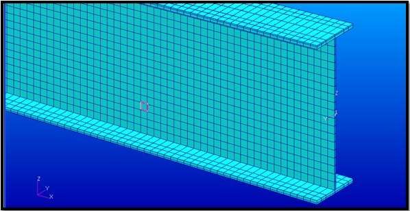
Vol-7 Issue-1 2021                                                                     IJARIIE-ISSN(O)-2395-4396

 applied burdens; to give an aerodynamic shape and to secure passengers, payload frameworks, and so forth. from
 the environmental conditions en-countered in flight. These requirements, in most airplane, bring about slight shell
 structures where the external surface or skin of the shell is generally supporte1d by longitudinal hardening
 individuals and transverse casings to empower it to oppose bowing, compressive and tensional loads without
 buckling. Such structures are known as semi-monologue, while slim shells which depend completely on their skins
 for their ability to oppose loads are alluded to as monologue.

1.1 Introduction to wing
 The wings are the most significant lift-creating part of the airplane. Wings change in configuration relying on the
 airplane type and its motivation. Most planes are planned so the external tips of the wings are higher than where
 the wings are connected to the fuselage. This upward point is known as the dihedral and helps shield the plane
 from moving startlingly during flight. Wings additionally convey the fuel for the plane. The components of aircraft
 wing are as shown in Figure 1.2. The shape of a wing greatly influences the performance of an airplane. The speed
 of an airplane, its maneuverability, its handling qualities, all are very dependent on the shape of the wings.

1.2 Introduction to wing spar
  An airplane wing is basically exposed to lift, fuel, motor, landing gear, inertial, basic, non auxiliary and other
 streamlined burdens. The principle load-bearing individuals in the wing are called fights. Fights are solid pillars
 which run length astute in the wing and convey the power and minutes because of the range insightful lift
 circulation. The Figure 1.1 shows the schematic outline of the loads acting on the wing.

                                      Figure-1.2: loads following up on the wing

     Wings of airplane are joined at the root to the fuselage. Subsequently the fight pillars can be considered as a
 cantilever shaft for the plan reason. The harmony savvy weight and shear dispersions on every airfoil are conveyed
 to the fights by the wing skin and airfoil-molded auxiliary casings called ribs. The ribs help the wing keep its
 airfoil shape, and along with the skin and fights structure tubes and boxes which oppose wing winding or twist.
 The weight and shear circulations on the wing skin are gathered by the ribs and sent to the competes. The heaps on
 most ribs are generally little, however some may convey concentrated burdens from landing rigging, motors, or
 outside stores. Wing skins are normally very slender, so they every now and again have extra stiffeners or stringers
 appended to them. Stringers help send the skin surface burdens to the ribs and fights, and they help shield the skin
 from bowing a lot under burden. Basic segments of stabilizers and control surfaces are given similar names as
 comparative segments in wings.

1.3 Structural shapes of wing spar

For bars, for example, wing fights, a straightforward rectangular cross-area is once in a while utilized. For a similar
cross-sectional zone and weight per unit range, in any case, C-or I-molded cross segments will have higher
estimations of I, since they have a greater amount of their zone farther from their impartial tomahawks where the
anxieties are higher. I-molded cross-areas are exceptionally basic decisions for airplane fights. They might be

13614                                             www.ijariie.com                                                 918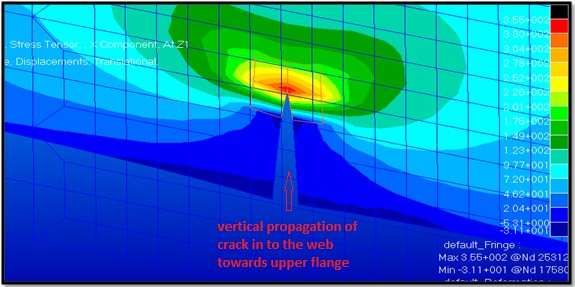
Vol-7 Issue-1 2021                                                                      IJARIIE-ISSN(O)-2395-4396

expelled entire or developed from pieces. As appeared in Figure 1.2 the top and base segments of the fight are called
fight tops and the moderately meager sheet of material associating them is known as the web. Fight tops are
basically stacked in strain and pressure, while the web is planned principally to oppose shear.

                                         Figure-1.3: Portions of a Built-Up Spar

1.4 Damage tolerance and Fatigue Failure Mechanism
Harm resistance is a property of a structure identifying with its capacity to continue surrenders securely until fix can
be influenced. The way to deal with building configuration to represent harm resistance depends on the assumption
that imperfections can exist in any structure and such defects proliferate with use. This methodology is normally
utilized in advanced plane design to deal with the expansion of breaks in structure through the use of the standards
of crack mechanics. In advanced plane design, structure is viewed as harm lenient if a support program has been
executed that will bring about the location and fix of inadvertent harm, consumption and weariness splitting before
such harm diminishes the lingering quality of the structure under a satisfactory cutoff. Harm lenient plan techniques
were built up that expect the structure contains introductory breaks. The underlying split generally dependent on as
far as possible. There are two general methodologies, with varieties, that might be followed to ensure that the
structure doesn't fizzle in administration. Slow crack growth is the moderate split development plan measures select
segment material and sets feelings of anxiety so the accepted previous break won't develop to disappointment during
administration and are the typical methodology for single burden way structure. For expanded wellbeing, the
permitted administration life as a rule got by separating the all out split development period by a factor of 2. The
part would need to be investigated as of now before proceeded with activity would be allowed. Fail-safe design is
plan idea accept the chance of numerous heap ways or potentially break capture highlights in the structure with the
goal that a solitary segment disappointment doesn't prompt quick loss of the whole structure. The heap conveyed by
the split part is quickly gotten by nearby structure and complete crack is evaded. It is fundamental. In any case, that
the first disappointment be distinguished and expeditiously fixed, on the grounds that the additional heap they
convey will abbreviate the exhaustion lives of the rest of the segments.

1.5 Modified virtual crack closure integral (MVCCI) method

The Modified Virtual Crack Closure integral method, originally proposed in 1977 by Rybicki and Kanninen is a very
attractive SIF extraction technique because of its good accuracy, a relatively easy algorithm of application capability
to calculate SIF for all three-fracture modes. Although the MVCCI method has a significant advantage over other
methods, it has not yet been implemented into most of the large commercial general-purpose finite element codes.
      The MVCCI method is based on the energy balance proposed by Irwin. In this technique, SIF
  is obtained for first fracture mode from the equation.

                                   Gi=            (i=1,2,3…….)

13614                                              www.ijariie.com                                                 919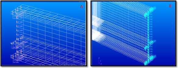
Vol-7 Issue-1 2021                                                                          IJARIIE-ISSN(O)-2395-4396

Where Gi is the energy release rate for mode I, Ki the stress intensity factor for mode i, E the elastic Modulus,        the
Poisson ratio,           for plane stress, and                 for plane strain. Calculation of the Energy release rate is
based on Irwin assumption that the energy released in the process of crack expansions equal to work required to
close the crack to its original state as the crack extends by a small amount of      .

Irwin computed this work as

                                W=

     Where u is the relative displacement, s the stress, r the distance from the crack tip, and Da the change in virtual
 crack length. Therefore, the energy release rate is

                      G=                =

2 FINITE ELEMENT ANALYSIS

Software description

 Software’s used in the present work are,

            Geometric modeling – CATIA V5

            Finite element modeling – MSC PATRAN

            Finite element solver –MSC NASTRAN

2.1 CATIA V5

     CATIA V5 is mechanical plan programming, tending to cutting edge measure driven plan necessity of the mechanical
 business. This device makes it workable for mechanical planners to rapidly outline thoughts, explore different avenues
 regarding highlights and measurements, and produce models and definite drawings. The accompanying orders are
 generally utilized in mathematical displaying. One can make mathematical drawing utilizing 2D portrayed calculation just,
 without reference to existing models or congregations. This outlined math can be constrained by relations (collinear, equal,
 digression, etc), just as parametric measurements. Expel, utilizing this alternative one can expel base highlights and
 different highlights utilizing 2D sketch. Spin order can makes a component that includes or eliminates material by
 spinning at least one profiles around a centerline. Example order can make a direct example, a roundabout example, a
 bend driven example, or use sketch focuses or table directions to make the example. Mirror, order duplicates the chose
 highlights or all highlights, reflecting them about the chose plane or face. Round example order used to makes different
 occasions of at least one highlights, which we can space consistently around a hub. Filet and Chamfer order can be utilized
 to make filet all edges of a face, chosen sets of appearances, chosen edges, or edge circles and slanted component on chose
 edges or a vertex. Cut, choice is utilized to manage highlights and 3Dmodel as for a characterized plane. In the current
 work mathematical models was made by utilizing every one of these orders.

2.2 Introduction to MSC Patran and MSC Nastran

    MSC Software Corporation is the biggest single supplier of limited component demonstrating and investigation
 (FEA) answers for the PC helped designing (CAE) market. MSC's items are advertised worldwide through
 workplaces in the United States, Europe, and Asia Pacific, and are accessible for use on frameworks extending

13614                                               www.ijariie.com                                                     920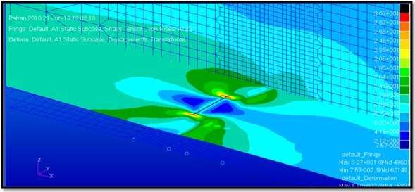
Vol-7 Issue-1 2021                                                                      IJARIIE-ISSN(O)-2395-4396

 from PCs to workstations and supercomputers. An overall limited component investigation can be separated into 3
 standard undertakings; preprocessing, examination and post handling. The preprocessing task incorporates building
 the mathematical model, fabricating the limited component model, giving these components the right properties,
 defining the limit conditions and stacking conditions lastly, amassing these components into an associated structure
 for investigation. The examination stage basically understands for the obscure degrees of opportunity, just as
 responses and stresses. In the post processing stage, the outcomes are assessed and shown. The exactness of these
 outcomes is proposed during this post processing task. The Patran and Nastran programming together play out
 every one of the 3 of the guideline assignments of a limited component examination. The pre and post processors
 are interesting to PATRAN itself. Nonetheless, this bundle permits the client to do the genuine arrangement
 examination on a wide range of bundles. At numerous destinations you have the alternative of utilizing the
 MSC/Nastran bundle, which is presumably the most broadly utilized solver in industry. A significant number of
 different bundles generally utilized in modern settings (ABAQUAS, ANSYS, MARC) are additionally viable with
 PATRAN.

2.3 Finite Element Meshing

 Limited component displaying is vital to the capacity to play out a designing butt-centric y sis of a model utilizing
 a PC. One of the center qualities of Patran is its capacity to assist you with making a limited component model,
 either from a current math model or through direct limited component activities. The equations expected to decide
 the conduct of a whole intricate model are frequently so convoluted that it is unreasonable to infer or fathom them.
 The limited element method takes care of this issue by isolating the intricate model into a collected gathering of
 limited components, little interconnected pieces normally alluded to as a work. The components in a limited
 component model have normal mathematical shapes, for example, square shapes, triangles, also, tetrahedral. They
 likewise incorporate associating focuses called hubs, and doled out material and component prop-erties. When the
 model is isolated into limited components, the PC examination program would then be able to utilize productive
 numerical conditions to ascertain the conduct of the individual components, considering the interde-dubiousness of
 contiguous components and the appointed properties. By changing over the calculation model into a limited
 component model made out of interconnected pieces, a PC can examine the model's conduct essentially and
 precisely.
 Patran gives the accompanying abilities to limited component demonstrating (FEM):

 1. Mesh cultivating apparatuses to control explicit work densities in explicit regions of your calculation.
 2. Several profoundly mechanized procedures for work age.
 3. Equivalencing abilities for joining networks in neighboring locales.
 4. Tools to confirm the quality and precision of your limited component model.
 5. Capabilities for direct information and altering of limited component information.

 These tools help minimize the human effort needed to reach your most important goal understanding the behavior
 of a geometric model while providing the flexibility to have as much control over the process as you need.

2.4 Material Modeling
 In Patran, a material is characterized as a named gathering of material-related properties that are applicable for a
 specific limited component investigation. Material properties mention to Patran what your model is made of (steel,
 a composite, and so on.) and characterize the characteristics of that material, (for example, thickness, firmness,
 explicit warmth, flexible modulus, Poisson's proportion, etc). Patran provides a materials application form and
 several sub forms that allow you to create, modify, show and delete materials. When you define a material
 property, it is not yet associated with the finite element model. Only when the element property is created, is the
 material is then associated with the model. It is the element property that references both the model and the
 material.After selecting the type of material model that best represents the behavior of a material, you build the
 material model by specifying the appropriate material properties. To manually input material property values, you
 use Patran’s Material Property application forms.
2.5 Assigning Elemental Properties
You can use the Element Properties application to create, modify, delete, and show sets of properties associated with
particular finite element types, and to assign these property sets to Geometry or FEM entities in your model. Some

13614                                             www.ijariie.com                                                921
Vol-7 Issue-1 2021                                                                        IJARIIE-ISSN(O)-2395-4396

element types are a shell, beam, rod, and spring. Examples of element properties are the thickness of a shell, the
spring constant for a spring, or an area for a bar element. Materials are element properties, and they are assigned to the
model via element property set assignment. The arrangement of element property options is unique for each analysis
code and type. You will need to refer to your analysis code documentation for complete information about the
supported options. Combinations of element property options are often given special element names within a
particular analysis code implementation. For example, a commonly used element in MSC Nastran is the Standard
Homogeneous Plate. This element results from choosing a combination of 2D, Shell, standard and homogeneous
options, and quad4 topology on the Element Properties form.

2.6 Assigning Load and Boundary Condition
 Most analysis problems involve the solution of how a model behaves in response to some action on this model–a
 force, a pressure, a temperature, or perhaps a magnetic field. In analysis terminology these actions are known as
 loads. Similarly, most models have certain conditions constraining their behavior. For example, an end of a
 cantilever beam fixed to a wall, or an adiabatic (non-conducting) boundary in a thermal problem. These constraints
 are referred to as boundary conditions. There is a great deal of similarity in both of these quantities. Both are
 applied to portions of your model, and some quantities may in fact be used as both loads and boundary conditions.
 Hence, a common set of operations is used within Patran to create both loads and boundary conditions.
     The specific loads and boundary conditions available to you depend upon the analysis program you are using
 with Patran. Both load and boundary conditions can be applied to either your geometric model or your finite
 element model. Both quantities have the important feature of being independent of the finite element model itself.
 In Patran, loads and boundary conditions are treated as a single type of data to be assigned to portions of your
 geometry or finite element model. As mentioned above, the specific load and boundary condition data which you
 can assign is highly analysis dependent.

3 STRESS ANALYSIS OF SPAR BEAM
                       The wing spar with top and bottom skin model is first prepared in the Catia V5 modelling
 programming and afterward separated into the product where limited component lattice and investigation is done.
 The product utilized for examination here is Patran. Limited component fitting is completed for all the parts of the
 wing fight. The Figure 5.1 shows the subtleties of the limited component work created on each piece of the
 structure utilizing MSC PATRAN.

                      Figure3.1: Finite element meshing of wing spar with top and bottom skin

13614                                              www.ijariie.com                                                   922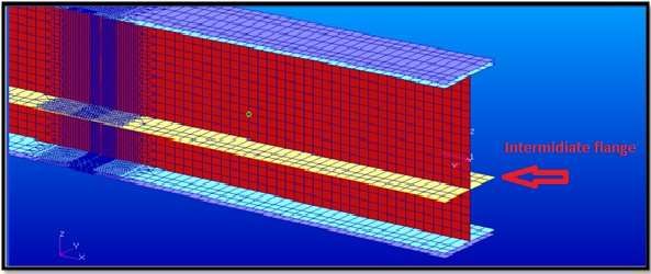
Vol-7 Issue-1 2021 IJARIIE-ISSN(O)-2395-4396
Figure3.2: Close up view of wing spar with top and bottom skin
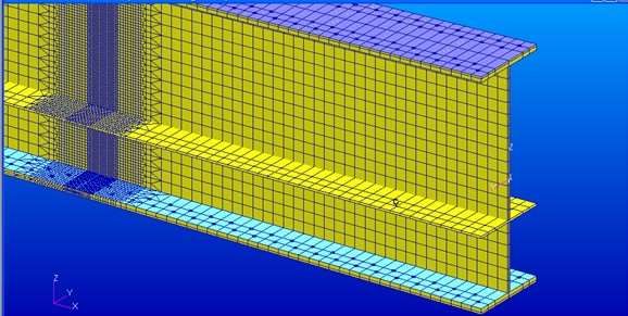
Figure3.3: Finite element meshing of different structural elements of wing spar
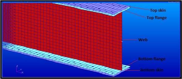
Figure3.4: The 2D mesh display in 3D form to visualize the thickness of the members in the wing spar model
13614 www.ijariie.com 923
Vol-7 Issue-1 2021                                                                      IJARIIE-ISSN(O)-2395-4396

        Figure3.5: Close up view of wing spar showing the thickness of the all the structural members of wing spar

                                        Table3.1: SIF calculated by analytical method

  Crack       Elemental              Nodal                          Forces at             Strain energy       SIF
  length        length        Displacements in mm                  nodes in N              release rate G      In
                                                                                                            Mpa
  in mm        in mm                                                                      in Kg/mm
                             ∆V1       ∆V2        ∆V        ∆F1       ∆F2        ∆F

    20            1        0.0899     0.0870    0.0028     45.34      46.78     92.1           67.7          2.156

    40            1         0.091     0.0868    0.0042     64.09      66.15     130.2         139.97         3.078

    60            1        0.0922     0.0870    0.0052     78.96      81.52     160.4          210.8         3.804

    80            1        0.0937     0.0876    0.0061     92.08      95.09     187.1         287.66         4.444

    100           1        0.0955     0.0885    0.007     104.35     107.78     212.1          370.2         5.041

    120           1        0.0976     0.0898    0.0078    116.31     120.14     236.4         461.07         5.626

    140           1          0.1      0.0914    0.0085    128.33     132.57     260.9         561.15         6.207

    160           1         0.103     0.0936    0.0094    140.75     145.41     286.1         675.55         6.811

    180           1        0.1065     0.0961    0.0103    153.92     159.02     312.9         808.34         7.45

    200           1        0.1106     0.0993    0.0113     173.8      173.8     342.0         965.92         8.144

13614                                            www.ijariie.com                                                    924
Vol-7 Issue-1 2021                                                                     IJARIIE-ISSN(O)-2395-4396

4 CRACK ANALYSIS OF WING SPAR

Figuring of pressure power factor utilizing Modified Virtual Crack Closure Integral (MVCCI) technique is
accomplished for every single break length beginning from the most extreme pressure got at the bolt opening in the
bottom flange where we got maximum stress. Then this SIF calculation is continued to the different crack lengths up
to the web of the wing spar when the bottom flange and bottom skin is been fully cracked and opened. Then after
once again crack propagation is done up to 1/3rd length of web. In this procedure of crack analysis no of iteration has
done for different crack lengths to reach 1/3 rd length of web. And at each crack lengths means for each iteration
calculate SIF value.

                               Figure 4.1: Maximum stress at the rivet hole position

                             Figure 4.2: Close up view’s of maximum stress at crack tip

                  Figure 4.3: Crack propagation reached vertical web of the wing spar beam

13614                                             www.ijariie.com                                                 925
Vol-7 Issue-1 2021                                                                      IJARIIE-ISSN(O)-2395-4396

           Figure 4.4: Complete opening of bottom flange when crack propagation reached web of spar

                                     Table 4.1: SIF values from 1st to 8th iteration.

     Crack Element                  Nodal                           Forces at                 Strain    SIF
              al               Displacements in                    nodes in N                 energy     in
     lengt                                                                                                  √
     h in   length                   mm                                                        release Mpa
     mm     Oc in            ∆V1      ∆V2        ∆V         ∆F1         ∆F2         ∆F        rate G in  m
             mm                                                                               Kg/mm
        7.07     1.64       0.881     0.863 0.018           65.2        64.3      129.51        0.2376 12.65
        14.16    1.64       0.888     0.859 0.029           88.6         89       177.64        0.5222 18.75
        21.24    1.64       0.896     0.857 0.038         107.29       108.8      216.09        0.8414    23.8
        28.3     1.64       0.903     0.856 0.047         124.25      126.95      251.21        1.1929 28.34
        35.39    1.64       0.912     0.857 0.055         141.02      145.01      286.04        1.5965 32.79
        42.49    1.64       0.923     0.859 0.064         159.42      164.69      324.12        2.0911 37.53
        49.57    1.64       0.937     0.864 0.074         183.07      189.99      373.07        2.7798 43.27
        56.66    1.64       0.980     0.884 0.095         361.93      361.92      723.86         7.000   68.67

13614                                          www.ijariie.com                                               926
Vol-7 Issue-1 2021 IJARIIE-ISSN(O)-2395-4396
Figure 4.5: The graph of crack length Vs SIF up to 8 th iteration
Figure 4.6: Vertical propagation of crack in to the web towards upper flange
Figure 4.7: Close up view of complete opening of bottom skin and bottom flange
13614 www.ijariie.com 927Vol-7 Issue-1 2021 IJARIIE-ISSN(O)-2395-4396
Table 4.2: Crack propagation result of wing spar
Crack Elemental Nodal Forces at Strain energy SIF
length length Oc Displacements in mm nodes in N release rate G in
in mm in mm in Kg/mm Mpa
∆V1 ∆V2 ∆V ∆F1 ∆F2 ∆F
7.07 1.64 0.881 0.863 0.018 65.2 64.3 129.51 0.2376 12.65
14.16 1.64 0.888 0.859 0.029 88.6 89 177.64 0.5222 18.75
21.24 1.64 0.896 0.857 0.038 107.29 108.8 216.09 0.8414 23.8
28.3 1.64 0.903 0.856 0.047 124.25 126.95 251.21 1.1929 28.34
35.39 1.64 0.912 0.857 0.055 141.02 145.01 286.04 1.5965 32.79
42.49 1.64 0.923 0.859 0.064 159.42 164.69 324.12 2.0911 37.53
49.57 1.64 0.937 0.864 0.074 183.07 189.99 373.07 2.7798 43.27
56.66 1.64 0.980 0.884 0.096 361.93 361.92 723.86 7.000 68.67
63.77 1.77 1.245 1.009 0.237 892.27 908.2 1800.5 24.005 127.16
70.87 1.77 1.265 1.018 0.247 939.15 949.26 1888.4 26.236 132.94
81.53 1.77 1.284 1.024 0.259 990.21 997.92 1988.1 29.03 139.86
88.64 1.77 1.300 1.029 0.271 1034.08 1042.46 2076.5 31.66 146.05
95.74 1.77 1.317 1.034 0.283 1082.09 1089.73 2171.8 34.63 152.73
102.85 1.77 1.336 1.039 0.297 1133.34 1141.00 2274.3 37.97 159.93
109.95 1.77 1.357 1.046 0.311 1188.25 1196.13 2384.4 41.74 167.78
117.06 1.77 1.380 1.054 0.326 1247.23 1255.69 2502.9 45.99 176.03
124.16 1.77 1.407 1.064 0.343 1310.74 1319.97 2630.7 50.82 185.03
131.27 1.77 1.436 1.075 0.361 1379.33 1389.62 2769 56.31 194.78
138.37 1.77 1.469 1.088 0.381 1453.67 1465.33 2919 62.59 205.35
141.63 1.77 1.497 1.100 0.397 1513.89 1526.31 3040.2 67.91 213.89
Figure 4.8: Crack propagation result of wing spar.
13614 www.ijariie.com 928Vol-7 Issue-1 2021 IJARIIE-ISSN(O)-2395-4396
Figure 4.9: Finite element meshing of wing spar beam with intermediate flange
Figure 4.10: Close up view of meshing of wing spar beam with intermediate flange
Figure 4.11: Close up view of alternate design of wing spar showing the thickness of all members
13614 www.ijariie.com 929Vol-7 Issue-1 2021 IJARIIE-ISSN(O)-2395-4396
Figure 4.12: Close up view of load and boundary conditions for alternate design of wing spar
Figure 4.13: Close view of crack at the bottom flange of spar beam in 1st iteration
13614 www.ijariie.com 930Vol-7 Issue-1 2021 IJARIIE-ISSN(O)-2395-4396
Table 4.3: SIF values for different crack lengths for crack arresting
Crack Elemental Nodal Forces at Strain Energy 1.SiF
length length Oc Displacements in mm nodes in N release rate in
√
in mm in mm G in Kg/mm Mpa m
∆V1 ∆V2 ∆V ∆F1 ∆F2 ∆F
7.07 1.64 0.834 0.815 0.019 66.85 67.58 134.44 0.27 13.51
14.16 1.64 0.84 0.812 0.0275 82.99 84.73 167.73 0.46 17.77
21.24 1.64 0.862 0.825 0.0368 102.39 105.23 207.62 0.77 22.87
28.3 1.64 0.853 0.809 0.0441 116.54 120.31 236.85 1.06 26.72
35.39 1.64 0.877 0.824 0.052 134.74 139.59 274.34 1.468 31.44
42.49 1.64 0.871 0.811 0.059 150.05 155.04 305.1 1.855 35.35
49.57 1.64 0.884 0.815 0.069 172.07 178.38 350.46 2.452 40.64
56.66 1.64 1.086 0.846 0.09 343.47 343.46 687.33 6.32 65.25
63.77 1.77 1.138 0.926 0.2115 796.38 811.16 1607.54 19.14 113.55
70.87 1.77 1.133 0.907 0.2256 800.84 825.59 1626.44 20.66 117.98
81.53 1.77 1.128 0.905 0.2227 849.02 856.53 1705.56 21.38 120.02
88.64 1.77 1.122 0.894 0.2279 863.7 881.6 1745.31 22.39 122.81
95.74 1.77 1.114 0.882 0.2326 881.71 899.98 1781.7 23.33 125.38
102.85 1.77 1.104 0.867 0.2367 902.4 909.88 1812.28 24.15 127.55
109.95 1.77 1.091 0.851 0.2396 912.87 920.45 1833.33 24.73 129.07
117.06 1.77 1.074 0.833 0.2406 915.89 923.76 1839.66 24.92 129.58
124.16 1.77 1.051 0.812 0.2387 906.67 914.72 1821.4 24.47 128.41
131.27 1.77 1.02 0.789 0.231 874.4 881.92 1756.34 22.84 124.05
138.37 1.77 0.991 0.779 0.2115 790.88 788.65 1579.54 18.81 112.57
141.63 1.77 0.917 0.772 0.1455 575.25 605.74 1181 9.67 80.73
Figure 4.14: Crack arrest result of wing spar
13614 www.ijariie.com 931Vol-7 Issue-1 2021 IJARIIE-ISSN(O)-2395-4396
5 RESULTS AND DISCUSSIONS
Figure 5.1: Crack propagation result of wing spar
Figure 5.2: Crack arrest result of wing spar
13614 www.ijariie.com 932Vol-7 Issue-1 2021 IJARIIE-ISSN(O)-2395-4396
Figure 5.3: Comparative results for crack analysis for both designs.
In the above Figure 5.3 we can observe that crack propagation curve for ordinary design is crossing the fracture
toughness curve at some crack length. This results in catastrophic failure of component. And crack propagation
curve of altered design of wing spar is well within the limiting range. This concludes that even in presence of crack,
spar with altered design or damage tolerant design can carry the design limit load till next inspection. And in this
project the fracture toughness value is taken from the book Fracture Resistance of Aluminum alloys published by
ASM International.
6 CONCLUDING REMARKS
• Stress analysis of wing spar is carried out and maximum stress is identified at the rivet hole location in the
bottom flange of the wing spar.
• Maximum tensile stress of 22.3 kg/mm2(218.763 N/mm2) is observed.
• A fatigu crack normally initiate from the location of maximum tensile stress in the wing spar structure as
predicted from the stress analysis.
13614 www.ijariie.com 933Vol-7 Issue-1 2021 IJARIIE-ISSN(O)-2395-4396
• Crack analysis is done on wing spar by initiating crack at maximum stress location and crack propagated in
bottom flange then to the vertically in to the web of spar up to the 1/3 rd length of web. And stress intensity
factor is calculated for different crack lengths using several iterations.
• At 56.66 mm crack length the SIF value crosses fracture toughness and leads to failure of wing spar.
• The structural design of spar is modified to make it damage tolerant by introducing one intermediate flange
in between top and bottom flange. And crack analysis is done on this design.
• The maximum value of SIF for this analysis is 129.58 MPa√m for crack length of 117.06 mm after this for
next crack length SIF value starts decreasing.
• Comparing this maximum value of SIF 129.58 MPa√m with fracture toughness value of material 140
√
MPa m. The SIF value is less than fracture toughness of material. With this we can conclude that crack
propagation is arrested and it satisfies the fracture toughness criterion and hence design is safe.
By observing the above point we can conclude now the new altered design is damage tolerant. That is even in
the presence of crack wing spar is capable of carrying designed limit load at least till next inspection interval.
7 Bibliography
[1] Aircraft Structures – David J Peery, J.J.Azar.
[2] Fracture Resistance of Aluminium Alloys Notch toughness, Tear resistance and Fracture toughness – J.Gilbert
Kaufman.
[3] Introduction to Aircraft Aeroelasticity and Loads – Jan R Wright, Jonathan E Cooper.
[4] Mechanics and Mechanism of Fracture: An Introduction – Alan F Liu
[5] Airframe Structural Design – Michael Chun Yung Niu
[6] Aircraft Conceptual Design Synthesis – Denis Howe.
[7] ASM HAND BOOK Volume 19 Fatigue and Fracture.
[8] Metals Hand Book Desk edition – ASM International.
[9] Mechanics of Aircraft Structures – C. T Sun.
[10] DAMAGE TOLERANCE OF AIRCRAFT PANELS - P. M. S. T. de Castro, S. M. O. Tavares, V. Richter-
Trummer, P. F. P. de Matos, P. M. G. P. Moreira, L. F. M. da Silva
[11] Stress and fracture analysis of riveted joints - GALİP KEÇELİOĞLU
[12] Virtual crack closure technique: History, approach, and applications - NASA/CR-2002-211628 ICASE
Report No. 2002-10 – Ronald Krueger National Institute of Aerospace, Hampton.
[13] Stress intensity factors by numerical evaluation in cracked structures - S.M.O. TAVARES, P.M.G.P.
MOREIRA, S.D. PASTRAMA, P.M.S.T. CASTRO
[14] Simple formulas for strain-energy release rates with higher order and singular finite elements - I. S. Raju
[15] Damage tolerant repair techniques for pressurized aircraft fuselages - WL-TR-94-3134 - CAPT ROBERT S.
FREDELL.
13614 www.ijariie.com 934Vol-7 Issue-1 2021 IJARIIE-ISSN(O)-2395-4396
[16] FATIGUE DAMAGE IN AIRCRAFT STRUCTURES, NOT WANTED, BUT TOLERATED? - Jaap Schijve
[17] MULTIPLE SITE DAMAGE IN AIRCRAFT STRUCTURE - Report LR 729 – July 1993 – J. Schijve.
[18] Model of the multi-site fatigue damage in the thin-walled structure - Proceedings of the 5th International
Conference RelStat’05 - Vitaly Pavelko, Julija Timoshtchenko.
[19] Initiation and distribution of multiple-site damage (msd) in a fuselage lap joint curved panel - Abubaker
A. Ahmed - FAA-Drexel Fellowship Student.
[20] Understanding crack growth in fuselage lap joints - R.Jones, L.Molent, S.Pitt – Theoretical Applied Fracture
Mechanics MSD 49.
[21] AIRCRAFT LOADS - Dr. M. Neubauer, G. Günther - DaimlerChrysler Aerospace GmbH.
[22] Damage Tolerance Assessment Handbook - DOT-VN TSC-FAA-93-13.Volume 11: Airframe Damage
Tolerance Evaluation.
[23] Damage Tolerance Assessment Handbook Volume I: Introduction Fracture Mechanics Fatigue Crack
Propagation.
[24] Introduction to Fracture Mechanics - C.H. Wang - Airframes and Engines Division - Aeronautical and
Maritime Research Laboratory - DSTO-GD-0103. [28] application of modern aluminum alloys to air- craft -
E. A. Starke and J. T. Staleyt – Pergamon - 0376–0421(95)00004-6.
[25] Analysis anddesign of flight vehicle structures - E.F. Bruhn.
[26] MSC SOFTWARE - NASTRAN AND PATRAN LIBRARAY.
[27] Aircraft Basic Construction chapter 4
Aerobasics–An Introduction to Aeronautics – S.P.GovindaRaju.
13614 www.ijariie.com 935You can also read