Dielectric and Flash-over Characteristics of the 1100kV Valve Side Converter Transformer Bushing with SF6 Gas Insulation
←
→
Page content transcription
If your browser does not render page correctly, please read the page content below

Journal of Physics: Conference Series

PAPER • OPEN ACCESS

Dielectric and Flash-over Characteristics of the ±1100kV Valve Side
Converter Transformer Bushing with SF6 Gas Insulation
To cite this article: Zhang Shiling and Song Wei 2021 J. Phys.: Conf. Ser. 1948 012080

View the article online for updates and enhancements.

                               This content was downloaded from IP address 46.4.80.155 on 20/08/2021 at 08:52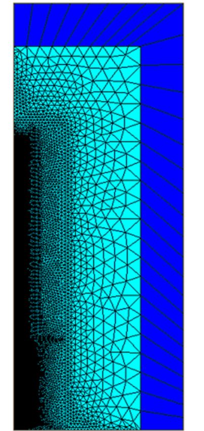
IoTAIMA 2021                                                                                                    IOP Publishing
Journal of Physics: Conference Series                         1948 (2021) 012080          doi:10.1088/1742-6596/1948/1/012080

Dielectric and Flash-over Characteristics of the ±1100kV
Valve Side Converter Transformer Bushing with SF6 Gas
Insulation

                     Zhang Shiling1*, Song Wei1
                     1
                      State Grid Chongqing Electric Power Company Chongqing Electric Power Research
                     Institute, Chongqing, 401123

                     zhangshiling@cq.sgcc.com.cn

                     Abstract. The ±1100kV high voltage capacitor filled SF6 gas bushing is an important
                     equipment to realize the electrical connection between the converter transformer and the valve
                     tower. The paper mainly discusses the design of the external and internal insulation structure.
                     The research content is divided into four parts, the actual operating environment and the
                     characteristics of the voltage and current waveform of converter transformer bushing are
                     discussed. The design and analysis of the hollow composite insulator, corona ring and tail end
                     of the bushing have been done. The main insulation structure of bushing has been designed by
                     the equal margin method, and simulation and analysis of the multi-physical field have been
                     done. The three dimensional electric field simulation model has been set up to calculate and
                     analyze the external insulation performance of the bushing. The results show that the main
                     insulation of the bushing is fit to the capacitance structure, the maximum axial field strength of
                     the bushing is 0.62kVꞏmm-1, and the end of the bushing should be equipped with apple type
                     corona ring. The insulation distance of the hollow composite insulator is designed as 7490mm.
                     The insulation distance of the bushing tail is designed as 3110mm. In the actual operating
                     environment, the maximum field strength of the corona ring appears on the lower end surface,
                     and the value is 2386Vꞏmm-1. The results of the paper can provide the theoretical basis for the
                     design of the external insulation of the converter transformer bushing used in the HVDC
                     transmission project.

1. Introduction
With the development of ±1100kV DC transmission strategy in China, higher requirements are put
forward for the DC transmission and transformation equipment, especially the development of core
equipment ±1100kV converter. As an important component of converter, the valve side sleeve of the
converter transformer has many theoretical and technical problems which are worth in-depth
discussion in the design of insulation structure. The technical specification for the development of ±
1100kV HVDC transmission equipment converter transformer volume stipulates that the lightning
impulse withstand and operation impulse withstand of converter transformer bushing are 1.05 times
higher than that of converter transformer, and the DC withstand, polarity reversal and power frequency
withstand test level are increased by 1.15 times[1-4]. The external insulation design and core interface
treatment with large margin are required to meet the requirements of lightning impulse and operation
impulse withstand voltage assessment. Meanwhile, the surface of fittings inside the sleeve is smooth
and the outer wheel profile structure design is reasonable. The polarity reversal voltage promotion

              Content from this work may be used under the terms of the Creative Commons Attribution 3.0 licence. Any further distribution
              of this work must maintain attribution to the author(s) and the title of the work, journal citation and DOI.
Published under licence by IOP Publishing Ltd                          1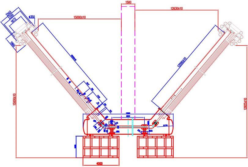
IoTAIMA 2021                                                                               IOP Publishing
Journal of Physics: Conference Series          1948 (2021) 012080    doi:10.1088/1742-6596/1948/1/012080

assessment puts forward higher requirements for the design of the typical oil gap between the tail of
the bushing and the outlet device of converter transformer. In design of bushing insulation structure of
±1100kV converter transformer, it will be difficult to manufacture, transport and install the bushing if
only the proportion of the physical size of the bushing and operating voltage value is only considered.
Therefore, the optimization design can be made in the main insulation structure of the bushing and the
insulation coordination at the tail of the sleeve, so the design margin of the sleeve insulation structure
can be improved. At present, the paper proposes the method of equal margin design for the main
insulation structure suitable for UHV bushing, which can realize the compact structure design of
bushing core. Document [5] proposes the calculation method of the loss of the valve side bushing of
the ±800kV converter transformer quantitatively under the special operating environment. The paper
analyzes the coordination between the outlet device at the end of the valve side bushing and the
insulation at the end of the sleeve in the valve side of the converter transformer, and analyzes the
change law of the transient electric field under the condition of polarity reversal electric field. Based
on the above research and analysis results, the design of the insulation structure of the valve side
bushing of ±1100kV voltage class converter transformer is discussed theoretically.
   In this paper, the actual operation environment of ±1100kV converter transformer valve side
bushing is analyzed, and the typical voltage and the current waveform in the actual operation of
converter transformer bushing are given. According to the impulse voltage value, the bushing structure
size and the umbrella type of bushing composite insulator are determined. On this basis, the improved
equal margin method is applied to design the inner insulation structure of the converter valve side
bushing. The three-dimensional simulation calculation model of ±1100kV converter transformer
bushing is established, and the distribution law of electric field intensity in key parts under the actual
operation conditions is analyzed, and the reasonable type of bushing voltage balancing device is
proposed. The results of the quantitative analysis in this paper can provide theoretical basis for the
development of ± 1100kV converter bushing to a certain extent, and can also provide the certain
reference value for the operation and maintenance of other voltage level converter bushing.

2. Computational model
In the design scheme of dry bushing for ± 1100kV converter transformer, the capacitor core is epoxy
impregnated dry structure, and the main optimization design parameters are as follows: plate layer
number = 93; zero layer plate length = 11435mm; conductive rod diameter = 156mm; n layer plate
length = 3275mm; n layer plate diameter = 652mm. The overall installation of the dry bushing of ±
1100kV converter transformer is shown in Fig. 1.

             Fig.1 The finite element calculation model for the converter transformer bushing

   According to Figure 1, the three-dimensional finite element calculation model is established, as
shown in Figure 2. The improved equal margin design method for main insulation of HV bushing is
applied to the optimization design of the main insulation of UHV converter bushing. Firstly, the outer
profile parameters of UHV converter bushing are input: the radius r0 and length l0 of zero layer plate
are 67.5mm and 9344mm respectively, and the radius rn and length ln of n layer plate are 263mm and
3346mm respectively. The total number of plates in the bushing core is 93. The long-term working
voltage of bushing is set to 800kV, the 2h DC withstand voltage is set to 1455kV, and the rated current
carrying capacity is set to 5515A. Based on the large-scale finite element analysis, the influence of
model and the temperature factors on the electric field distribution of UHV converter core is further

                                                     2
IoTAIMA 2021                                                                                 IOP Publishing
Journal of Physics: Conference Series             1948 (2021) 012080   doi:10.1088/1742-6596/1948/1/012080

studied. According to the initial design of the insulation structure in UHV converter bushing and the
actual layout of converter bushing, the finite element solid model is established. The middle flange of
the converter bushing is installed on the lifting seat, and the end of the bushing is inserted into the oil
tank (inner diameter 1400mm). Load and boundary conditions: the air end equalizing ball, center
guide rod and oil equalizing ball are of high potential, and the applied voltage is the long-term
maximum working phase voltage of UHV converter bushing, Um=1100kV. The connection sleeve, oil
tank, earth and far field boundary are zero potential. The mesh generation of the converter bushing
model is shown in Figure 2.

                Fig.2 The finite element mesh division of the converter transformer bushing

                             Tab.1 The technical parameters of wall bushing
                Maximum continuous DC voltage                                 1122kV
         Applied DC withstand voltage (Positive polarity,
                                                                              1683kV
                           120min)
                  Test voltage (50Hz, 1min)                                   1096kV
        Lightning impulse withstand voltage test (full wave)                  2300kV
                     DC polarity reversal test                          -1400/+1400/-1400kV

   Figure 2 shows that the "U" type wall bushing is divided into indoor and outdoor parts compared
with the "one" traditional wall bushing, which avoids the manufacturing difficulty caused by the long
central guide rod of the "I" traditional wall piercing sleeve. But under the same distance between the
bushing high potential equalizing ring and the wall, the composite insulator needs a longer distance.
The U-shaped wall bushing transforms horizontal arranged central conductor structure into inclined
arrangement with certain angle, which reduces the eccentric phenomenon of conductor caused by long
length and too large self weight under horizontal arrangement. On the other hand, because of the
compact structure of "U" wall bushing, the electric field distribution of bushing is more concentrated,
which increases the risk of flashover in the bushing. Therefore, the three-dimensional electric field
simulation model of bushing is established to discuss and analyze the more accurate three-dimensional
electric field distribution of bushing, among which the technical parameters of wall bushing are shown
in Table 1.

                                                        3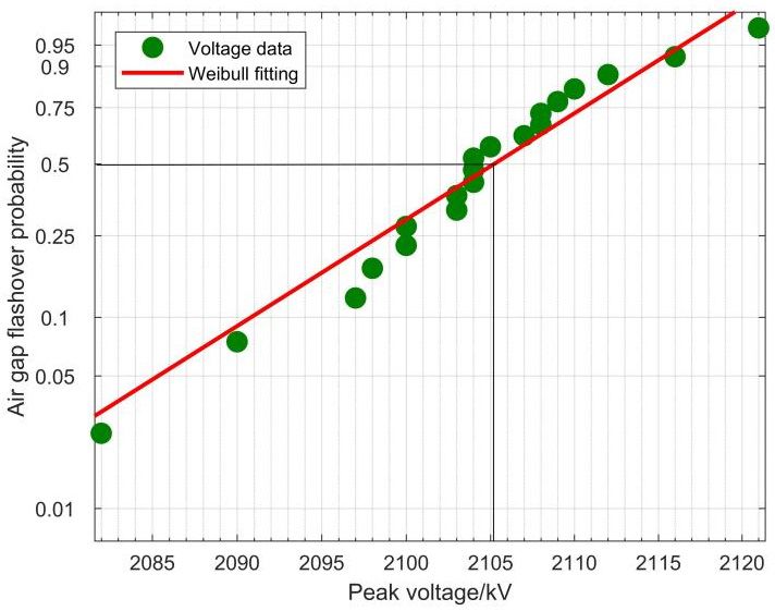
IoTAIMA 2021                                                                                     IOP Publishing
Journal of Physics: Conference Series               1948 (2021) 012080     doi:10.1088/1742-6596/1948/1/012080

3. Three dimensional electric field simulation results
In order to improve flashover voltage of the hollow composite insulator with high voltage converter
bushing, it is necessary to configure the end equalizing cover with the reasonable structure to evenly
distribute the voltage along the hollow composite insulator. In addition, there are some key structural
components at the end of the bushing, such as terminal block, bus bar fittings, bus bar outgoing line,
etc. after installing the grading ring at the end of the bushing, the sharp corners and protrusions on the
surface of the above irregular conductor can be effectively shielded, and the corona discharge and the
resulting external insulation flash-over can be suppressed.

                     (a) No corona equalizing cover          (b) Double ring equalizing cover

                  (c) Multi ring equalizing cover      (d) Apple type pressure equalizing cover
                        Fig.3 The structure type of high voltage bushing corona ring

    As shown in Figure 3(a), the high field strength area is concentrated at the edge of the bus fitting
without the grading cover, and the maximum field strength is 6.7kVꞏmm-1, which is 3kVꞏmm-1 higher
than the breakdown field strength of air. Therefore, corona discharge will be generated at the edge of
the fitting. After the double ring grading cover is installed, the bus fitting is located in the low field
strength area inside the grading cover, maximum field strength is reduced to 3.4kVꞏmm-1. Now the
pressure equalizing cover surface is shown in Figure 3(b). In order to further improve the electric field
distribution at the end of the bushing, the structure of multi ring grading hood can be adopted, as
shown in Figure 3(c). It can be seen that the position where the maximum electric field intensity
occurs is transferred to the middle part of the grading hood, and the maximum electric field intensity is
3.1kVꞏmm-1. Both double ring and multi ring equalizing hoods are used in high voltage substations,
but apple type equalizing hoods are generally used at the ends of power equipment in valve hall of
high voltage converter station, as shown in Figure 3(d). It can be seen that apple type grading cover
can completely cover the confluence fittings in the low field strength area, and the electric field
distribution on surface of grading cover is more uniform, its maximum field strength is 2.4kVꞏmm-1,
which is lower than the breakdown field strength of air 3kVꞏmm-1. Therefore, apple type grading cover
is used at the end of high voltage converter bushing, which can not only avoid its own corona, but also
inhibit the external insulation flashover along the hollow composite insulator [6-8].

                                                         4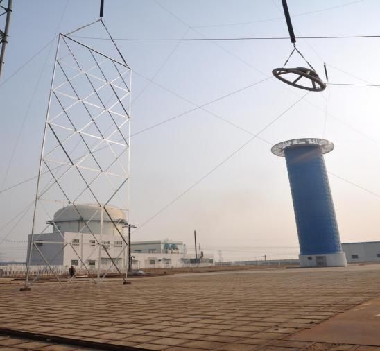
IoTAIMA 2021                                                                                    IOP Publishing
Journal of Physics: Conference Series              1948 (2021) 012080     doi:10.1088/1742-6596/1948/1/012080

    In order to ensure that the axial flashover does not occur at the end of the capacitor core under the
power frequency dry withstand test voltage of 1100kV, the maximum axial field strength of the
bushing is not greater than 0.90kVꞏmm-1, and the axial field strength is set as 0.6kVꞏmm-1 in the main
insulation design, so the sum of the step length is 1455/0.6=2418mm, and the insulation distance at the
end of the bushing should not be less than 2418mm. Combined with the actual rolling conditions of
bushing core, the insulation distance of bushing tail is designed as 3110 mm. The tail of converter
bushing core is the epoxy impregnated paper solid structure, and the outside is transformer oil. Its
insulation strength is higher than that of air, so the insulation distance of bushing tail is less than that
of hollow composite insulator. At the end of converter bushing, there are capacitor core, conducting
tube, metal base, current carrying terminal and other structures, as well as metal conductor, epoxy
impregnated paper, transformer oil and other media. There are many insulation structures and
insulation media in the narrow area of the bushing tail, and the electric field distribution is extremely
uneven. It is necessary to install the voltage sharing ball to improve the electric field distribution and
avoid corona, flashover and other insulation accidents. Three-dimensional electric field distribution at
the tail of converter bushing with and without voltage equalizing ball is shown in Figure 4, and the
applied voltage is 2405kV for lightning impulse test. The Figure shows that the maximum field
strength is located on the surface of the current carrying terminal when the equalizing ball is not
installed, and it is significantly reduced when the equalizing ball is installed.

                                        (a) No equalizing ball is installed

                                       (b) Install the equalizing ball
       Fig.4 The distribution of electric field in the end of the bushing with and without corona ring

4. Discussion on selection of bushing structure type
For higher safety margin, the insulation distance of bushing can be designed as 11m. In this test, the
space clearance of ±1100kV DC wall bushing designed on the other side is checked, and the design
structure is shown in Figure 5.

                                        Fig.5 Structural design drawing

                                                         5
IoTAIMA 2021 IOP Publishing
Journal of Physics: Conference Series 1948 (2021) 012080 doi:10.1088/1742-6596/1948/1/012080
The maximum diameter of the voltage sharing ring designed for the actual U-shaped structure
through wall bushing is 2893mm and the diameter is 350mm. In this test, the insulating corona sharing
ring is used to simulate the bushing corona sharing ring. As shown in Figure 6, the diameter of the
voltage sharing ring is 2500m and the diameter is 220mm.
Fig.6 Test grading ring Fig.7 Experimental simulation wall
In the test, the grounding tower frame is used to simulate the grounding wall, as shown in Figure 7.
The length of the tower frame is 18m, the width is 10m, and the bottom of the tower frame is 6m
above the ground. The test objects are arranged to simulate the actual operation of U-shaped DC
through wall bushing. The axial direction of grading ring is 50° to the ground. The arrangement of test
objects is shown in Figure 8.
Fig.8 Test layout
The Weibull distribution function with the two parameters is used to analyze the breakdown test
data. According to Weibull probability statistics theory, the breakdown probability of epoxy
impregnated paper under electric field E:
E
F ( E; , ) 1 exp 0.5
(1)
Where: E—Breakdown field strength/kV•mm-1; —Breakdown field strength at 50% breakdown
probability, scale parameter/kV•mm-1; —shape parameter. According to the size and location of
grading ring, the withstand voltage test of 12.6m to the wall and 12.9m to the ground was carried out.
The meteorological conditions during the test were as follows: temperature T = 5 ℃, relative humidity
r = 45%, air pressure P = 101.7kpa. Before the test, the meteorological correction was carried out for
6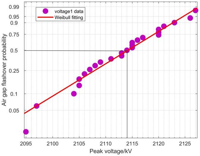
IoTAIMA 2021                                                                                IOP Publishing
Journal of Physics: Conference Series           1948 (2021) 012080    doi:10.1088/1742-6596/1948/1/012080

the 2100kV withstand voltage of the switching impulse, and the correction result was 2094kV. The
voltage withstand test result is shown in Figure 9. It shows that the 20 data points basically present a
linear distribution in Weibull coordinates, and the slight dispersion of the line just shows the reliability
of the test results. Taking 50% flashover voltage, the value is about 2105kV. At the same time, the
data points of 50% flashover voltage are relatively dense, which shows the rationality of taking 50%
flashover probability as the actual flashover voltage value.

            Fig.9 Test results under working conditions (10.5m to wall and 12m to ground)

   According to the meteorological correction results, the + 1% deviation tolerance test and the + 3%
deviation tolerance test are carried out for this working condition, and the test results are shown in
Figure. 10 and Figure. 11.

     Fig.10 +1% deviation tolerance test results          Fig.11 +3% deviation tolerance test results

    As shown in the figure above, the + 1% deviation tolerance test was conducted for 25 times, in
which the ground was discharged once in the 10th time, and the other 24 times were tolerant. The +
3% deviation tolerance test was conducted for 22 times, and there were 4 times of discharge, including
1 discharge to the ground and 3 discharge to the wall.
    Under power frequency and impulse voltage, the electrical performance of the bushing requires that
flashover discharge can not occur on the outer surface of the hollow composite insulator in the air and
the outer surface of the bushing core in the oil. The coordination of the internal and external insulation
of the bushing and the regulation of the external insulation of the core main insulation are the key to
the design of the external insulation of the bushing. The dry flashover voltage of the bushing hollow
composite insulator is close to the air gap breakdown voltage between the upper flange and the middle

                                                      7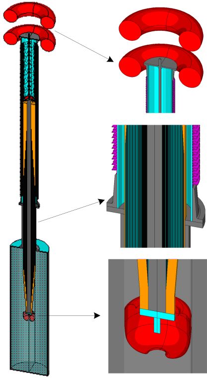
IoTAIMA 2021 IOP Publishing
Journal of Physics: Conference Series 1948 (2021) 012080 doi:10.1088/1742-6596/1948/1/012080
flange, which is mainly determined by the dry flashover distance Ld. The relationship between each
flashover voltage value and the dry flashover distance is shown in Figure 12. The figure above shows
that the flashover voltage of the bushing hollow composite insulator increases with the increase of
insulation distance, and there is saturation effect [9-11]. The curve in Figure 12 is fitted by formula (2),
and the fitting results are shown in Table 1.
U f 50 ALBd (2)
Where; Uf50 —— Flashover voltage (50% discharge probability)/kV; Ld —— External dry
flashover distance of insulator/m; A and B —— Coefficient to be determined.
Fig.12 The relationship between flashover voltage and insulation distance of hollow composite
insulator in standard atmospheric pressure
Considering the repeatability of the test, the voltage value with 99.9% withstand probability is
taken as the rated withstand voltage, and the ratio of the various flashover voltage values (50%
discharge probability) to withstand voltage is Ufn. Therefore, the relationship between withstand
voltage value Ufn and insulation distance Ld can be modified to equation (3) [12]:
U fn ALBd (1 3.08 ) (3)
The values of power frequency voltage, lightning impulse voltage and switching impulse voltage
are 5%, 3% and 6%, respectively. The lightning impulse voltage of high voltage bushing is 2405kV,
and Ld is about 5400mm by substituting it into equation (3). Similarly, by substituting the relevant
parameters of power frequency dry withstand test voltage 1100kV (effective value) and switching
impulse test voltage 1843kV into equation (3), the required insulation distances Ld under various
voltages are 5230mm and 7350mm respectively, so the dry flashover distance of high voltage bushing
hollow composite insulator should at least be greater than 7350mm. In the umbrella structure design of
high voltage bushing hollow composite insulator, an open umbrella structure is adopted, and the
umbrella structure section is shown in Figure 13.
Fig.13 Hollow composite insulator umbrella type structure of high voltage bushing
8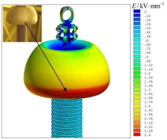
IoTAIMA 2021 IOP Publishing
Journal of Physics: Conference Series 1948 (2021) 012080 doi:10.1088/1742-6596/1948/1/012080
It can be calculated from Figure 13 that the net increased creepage distance of a single group of
large and small umbrellas is 152mm, the distance between large umbrellas is 55mm, the ratio of the
width of large umbrellas to the distance between adjacent large umbrellas is 0.91, and the creepage
distance LX of external insulation can be calculated by formula (4):
Lx nv h (4)
Where: n is the number of large and small umbrella groups; v is the increased leakage distance of
a group of large and small umbrella/mm; h is the insulation distance of hollow composite insulator/
mm. The minimum nominal creepage distance Lc of converter bushing can be calculated as follows:
Lc U r kD (5)
Where: is the minimum nominal creepage distance, unit: mm/kV, taken as 25mm/kV; U r is the
rated voltage, unit: kV, taken as 800kV; kD is the diameter coefficient, for the average diameter of
insulator greater than 500 mm, creepage distance shall be corrected by 1.2 times[13-17]. According to
formula (5), the minimum nominal creepage distance LC of the converter bushing is 24000 mm.
Taking a certain safety margin, LC is required to be greater than 26630 mm. Therefore, 136 sets of
large and small umbrellas are proposed in the design, and the insulation distance of the hollow
composite insulator should not be less than 5958 mm. According to the manufacturing conditions and
specifications of the hollow composite insulator, the insulation height is designed to be 7490 mm, and
the outer diameter of the large umbrellas is 835 mm. The outer diameter of the small umbrella is
803mm, and the inner diameter of the hollow composite insulator is 687mm.
Fig.14 The electric strength distribution of inner and outer surface of hollow composite insulator
The field strength distribution along surface of hollow composite insulator is checked and
calculated by using the full model of high voltage bushing finite element calculation under the
lightning impulse test voltage of 2405kV. The vector sum and tangential components of the field
intensity on the inner and outer surfaces are intercepted, and the field intensity distribution is shown in
Figure 14. The results show that the vector sum of the field strength on the inner and outer surfaces of
the hollow composite insulator is greater than the tangential field strength, and the strong oscillation of
the field strength on the outer surface is mainly due to the alternating path of the field strength
interception along the surface of the big and small umbrellas. The abscissa of Figure 14 is
approximately equal to the creepage distance LX of the hollow composite insulator. The intercepting
path of the inner surface field strength does not pass through the umbrella, and the curve is relatively
smooth, and the abscissa of Figure 14 is approximately equal to the insulation height of the hollow
composite insulator. The maximum values of the inner and outer surface field strength vector sum are
9IoTAIMA 2021 IOP Publishing
Journal of Physics: Conference Series 1948 (2021) 012080 doi:10.1088/1742-6596/1948/1/012080
0.79kVꞏmm-1 and 0.82kVꞏmm-1 respectively, which meet the allowable value of 0.90kVꞏmm-1. The
maximum values of tangential field strength are 0.17kVꞏmm-1 and 0.38kVꞏmm-1 respectively, which
meet the allowable value of 0.40kVꞏmm-1.
5. Conclusion
a) Based on the analysis and research of flashover voltage, insulation distance, umbrella structure and
grading ball, the external insulation design of high voltage converter bushing is calculated and
analyzed: the insulation distance of bushing hollow composite insulator is 7490mm, and the insulation
distance of bushing tail is 3110mm; the flashover voltage and creepage distance of bushing air end and
oil end are higher than corresponding technical indexes. And installed equalizing ball can effectively
improve the electric field distribution at the end of the bushing.
b) The three-dimensional electric field distribution of the high-voltage converter bushing is
calculated by submodeling technology. The calculation results show that the maximum electric field
intensity of the end equalizing cap of the optimized converter bushing is 2386Vꞏmm-1 in the actual
operation environment. There is a local field concentration area in the bushing composite sheath, and
its field strength is 936Vꞏmm-1. The above two field strength values are lower than the external air
breakdown field strength of 3000Vꞏmm-1, so the converter bushing has a reasonable external
insulation design.
References
[1] LIU Zhen-ya, Ultra-high voltage power grid[M], Beijing, China: China Economy Press, 2005.
[2] YAN Zhang, ZHU De-heng. High voltage insulation engineering[M], Beijing, China: China
Electric Press, 2007.
[3] LIANG Xi-dong, High voltage engineering[M], Beijing, China: Tsinghua University Press,
2010.
[4] Liang Xuming, Zhang Ping, Chang Yong. Recent advances in high-voltage direct-current power
transmission and its developing potential[J]. Power System Technology, 2012, 36(4): 1-9.
[5] Xie Heng-kun. Electrical insulation design principles [M]. Beijing, China: Mechanical Industry
Press, 1992.
[6] Li Peng, Gu Chen, Chen Dong, He Huiwen, et al. Development of technologies in ±1500kV
UHVDC transmission research[J]. High Voltage Engineering, 2017, 43(10): 3139-3148.
[7] Zhang Xuecheng, Tan Jinhua, Niu Wanyu. Bushings design of converter transformer’s valve
side of UHVDC transmission project [J]. High Voltage Engineering, 2012, 38(2): 393-399.
[8] Zhang Shiling, Peng Zongren, Wu Hao. Analysis on power loss of valve-side RIP bushing for
±800kV converter transformer [J]. Power System Technology, 2014, 38(7): 1758-1764.
[9] Lin Xin, Wen Miao, Shen Wen, et al. Analysis on insulation property of converter transformer
bushing under complex voltage[J]. High Voltage Apparatus, 2015, 51(4): 1-6.
[10] Chen Zhong, Wu Heng, Huang Heyan, Chu Jinwei. Cause analysis and improvement measure
of ±800kV DC wall bushing occurring flashover during overvoltage withstand test[J]. High
Voltage Engineering, 2011, 37(9): 2133-2139.
[11] Hosokawa M, Okumura K, Yamagiwa T, et al. Dielectric performance of improved gas
insulated bushing for UHV GIS[J]. IEEE Transaction on Power Delivery, 1987, 2(2): 359-
366.
[12] Dexin Nie, Hailong Zhang, Zhong Chen, Xing Shen.Optimization Design of Grading Ring
and Electrical Field Analysis of 800kV UHVDC Wall Bushing[J]. IEEE Transaction on
Dielectrics and Electrical Insulation, 2013, 20(4): 1361-1368.
[13] Xie Qiang, Ma Guoliang, Hailong Zhang, Zhong Chen et al. Simulation calculation and
experimental research on harmonic losses in power transformers[J]. Power System
Technology, 2013, 37(12): 3521-3527.
[14] Zhang Liangxian, Chen Mosheng, Peng Zongren et al. Eddy current loss calculation and shield
analysis of UHV converter transformer[J]. TRANSFORMER, 2013, 50(3): 15-21.
10IoTAIMA 2021 IOP Publishing
Journal of Physics: Conference Series 1948 (2021) 012080 doi:10.1088/1742-6596/1948/1/012080
[15] Xie Qiang, Ma Guoliang, He Chang, et al. Shaking table test study on seismic performance of
1100kV gas insulated switchgear porcelain bushing[J]. High Voltage Engineering, 2016,
42(8): 2596-2604.
[16] Wen Miao, Lin Xin, Zhong Simeng. Numerical simulation and experimental study of heat
transfer characteristics in transformer bushing [J]. High Voltage Engineering, 2016, 42(9):
2956-2961.
[17] Xu Jianchun, Lu Peng. Performance of the pan-type insulator for 1100kV GIS[J]. Electric
Power Construction, 2010, 31(8): 91-93.
11You can also read