Eljen GSF System Ontario Design and Installation Manual
←
→
Page content transcription
If your browser does not render page correctly, please read the page content below

Eljen GSF System

                      Ontario
           Design and Installation Manual

                                            September 2020

            Manufactured By:                                        Represented By:

        Eljen Corporation                             Enviro-STEP Technologies Inc.
          Windsor, CT 06095                                         Quebec City (Qc)
            info@eljen.com                                       dmercier@enviro-step.ca
Tel: 800-444-1359 ▪ Fax: 860-610-04270                    Tel: 877-925-7496 ▪ Fax: 418-626-4090
            www.eljen.com                                       www.enviro-step.ca

2020 Ontario Design & Installation Manual        Page 1                                   www.eljen.com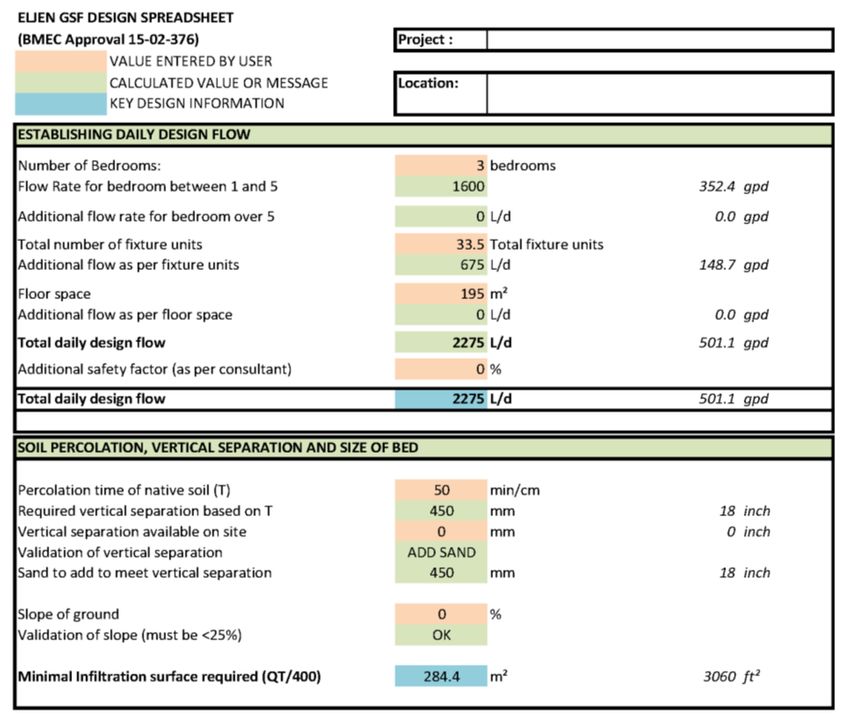
Table of Contents

SUBJECT                                                                                                                                 PAGE
        ELJEN GSF PERFORMANCE TESTING ......................................................................................... 3
        GLOSSARY OF TERMS ................................................................................................................... 4
        ELJEN GSF SYSTEM DESCRIPTION .............................................................................................. 6
        1.0 ELJEN GSF SYSTEM PRECONDITIONS .................................................................................. 7
        2.0 DESIGN AND INSTALLATION .................................................................................................... 8
        3.0 IN-GROUND, PARTIALLY RAISED OR RAISED SITE SYSTEMS .......................................... 14
        4.0 SLOPED SITE SYSTEMS ......................................................................................................... 15
        5.0 SYSTEM SIZING AND GUIDELINES ....................................................................................... 16
        6.0 LEVEL ABSORPTION BED INSTALLATION AND GUIDELINES ............................................ 19
        7.0 RAISED ABSORPTION BED INSTALLATION GUIDELINES .................................................. 24
        8.0 DOSING DISTRIBUTION GUIDANCE ...................................................................................... 27
        9.0 LOW-PRESSURE DISTRIBUTION GUIDANCE ....................................................................... 27
        10.0 SYSTEM VENTILATION ......................................................................................................... 29
        11.0 COMMERCIAL ELJEN SYSTEMS ......................................................................................... 31
        12.0 SYSTEM NOTES..................................................................................................................... 34
        13.0 SAMPLING DEVICE ............................................................................................................... 35

ELJEN GSF DRAWINGS AND TABLES
    DRAWINGS
      FIGURE 1: ELJEN GSF SYSTEM OPERATION ............................................................................. 6
      FIGURE 2: TYPICAL ELJEN GSF A42 CROSS SECTION ............................................................. 8
      FIGURE 3: VERTICAL SEPARATION DISTANCE .......................................................................... 9
      FIGURE 4: VERTICAL SEPARATION DISTANCE WITH IMPORTED SAND ................................ 9
      FIGURE 5: END-TO-END SEPARATION FOR ALL APPLICATIONS ............................................ 11
      FIGURE 6: AIR BY-PASS LINE FOR VENTING PUMPED SYSTEMS ........................................... 13
      FIGURE 7: LEVEL ABSORPTION BED PLAN ............................................................................... 14
      FIGURE 8: RAISED BED ON SLOPE ............................................................................................. 15
      FIGURE 9: EXAMPLE – ABSORPTION BED SHOWING SMALLEST CONFIGURATION ............ 19
      FIGURE 10: EXAMPLE – ABSORPTION BED WITH END-TO-END MODULES ........................... 19
      FIGURE 11: EXAMPLE – ABSORPTION BED WITH SPACED MODULES ................................... 19
      FIGURE 12: EXAMPLE – ABSORPTION BED WITH GROUPED MODULES ............................... 20
      FIGURE 13: EXAMPLE – ABSORPTION BED WITH SETBACK RESTRICTIONS........................ 20
      FIGURE 14: EXAMPLE – ABSORPTION BED WITH SETBACK RESTRICTIONS........................ 21
      FIGURE 15: EXAMPLE – ABSORPTION BED SYSTEM WITH IMPORTED SAND....................... 21
      FIGURE 16: EXAMPLE – IN-GROUND ABSORPTION BED SYSTEM .......................................... 21
      FIGURE 17: EXAMPLE – PARTIALLY RAISED ABSORPTION BED SYSTEM ............................. 21
      FIGURE 18: EXAMPLE – RAISED SYSTEM .................................................................................. 24
      FIGURE 19: EXAMPLE – SLOPED RAISED SYSTEM .................................................................. 24
      FIGURE 20: PRESSURIZED PIPE PLACEMENT .......................................................................... 27
      FIGURE 21: PRESSURE CLEAN OUT........................................................................................... 28
      FIGURE 22: CONTOURED TRENCH PRESSURIZED DISTRIBUTION ........................................ 28
      FIGURE 23: VENT LAYOUTS FOR GRAVITY AND LOW-PRESSURE SYSTEMS....................... 29
      FIGURE 24: ELJEN GSF SYSTEM WITH VENT EXTENDED TO CONVENIENT LOCATION ...... 29
      FIGURE 25: PRESSURE DISTRIBUTION VENTING BY-PASS LINE ........................................... 30
      FIGURE 26: PARTS AND DEVICES ............................................................................................... 35
      FIGURE 27: OBSERVATION AND SAMPLING PORT PREPARATION PLAN VIEW .................... 35
      FIGURE 28: PREPARING THE SAMPLING DEVICE LOCATIONS ............................................... 36
      FIGURE 29: PLACING THE SAMPLING DEVICES ........................................................................ 36
      FIGURE 30: PLACING SPECIFIED SAND OVER SAMPLING DEVICE ........................................ 37
      FIGURE 31: PLACING THE MODULE............................................................................................ 37
      FIGURE 32: COMPLETING BACKFILL .......................................................................................... 38

    TABLES
      TABLE 1: 12 MONTH NSF STANDARD 40 PROTOCOL PERFORMANCE RESULTS ................. 3
      TABLE 2: SUMMARY OF ONTARIO FIELD TESTING / SAMPLING .............................................. 3
      TABLE 3: SPECIFIED SAND SIEVE REQUIREMENTS ................................................................. 5
2020 Ontario Design & Installation Manual                          Page 2                                                       www.eljen.com
Eljen GSF Performance Testing

The Eljen GSF technology is based on scientific principles which show that improving the effluent quality before
infiltration in the native soil increases soil absorption rates and reduces risks of clogging. To ensure onsite
system designers can confidently specify Eljen’s GSF model A42 module, rigorous and official third-party
independent testing was conducted in accordance with the NSF/ANSI Standard 40 Protocol and actual Ontario
Eljen GSF System field testing / sampling.
Fecal Coliform, although not part of Standard 40 protocol, was also tested by the approved testing facility.
The NSF Standard 40 Protocol testing was also extended to cover a full 12 consecutive month period
instead of the minimal 6 months required by NSF Standard 40, this to verify the stability of the performances
and the capacity to handle colder weather conditions. Cold weather testing included 12 consecutive weeks
with influent temperature below 10°C.
It is relevant to mention that the Eljen GSF product has been used extensively throughout the United States
for decades and is also approved in six Canadian provinces (Ontario, BC, Manitoba, Nova Scotia,
Newfoundland and Saskatchewan).
The intrinsic characteristics of the Eljen GSF System, combining simplicity, robustness and optimized
natural biological processes make it one of the best options for onsite wastewater treatment.
For more information on our product testing, design standards, installation procedures or how the Eljen GSF
System meets high effluent quality, please contact Enviro-STEP Technologies at 1-877-925-7496 or the Eljen
Technical Support Department at 1-800-444-1359.
A summary of the test results from independent third-party testing using the NSF/ANSI Standard 40 Protocol are
listed below Table 1. A summary of Ontario field testing / sampling is presented in Table 2.

           TABLE 1: 12 MONTH NSF STANDARD 40 PROTOCOL PERFORMANCE RESULTS

              Eljen GSF A42 Modules Treatment Performance during official 12 months testing
                   (including 12 consecutive weeks with influent temperature below 10ºC)
                                 CBOD5 (mg/L)       TSS (mg/L)      Fecal Coliform (MPN/100ml)
          Average                       1.2             2.4                      66*
          Median                        1.0             1.0                      71*
          Min Value                     1.0             1.0                       2*
          Max Value                     8.3             11.0                   10 965*

                      TABLE 2: SUMMARY OF ONTARIO FIELD TESTING / SAMPLING

                            Eljen GSF A42 Ontario Field Testing / Sampling Summary
                                              CBOD5 (mg/L)                     TSS (mg/L)
           Average                                7.8                              9.7
           Median                                 5.0                              9.0
           Count                                  217                              76

                           The Eljen GSF System is described as an
                      Combined Advanced Treatment and Dispersal System.

   This Design and Installation Manual is complementary to the BMEC Authorization
            and Ontario Building Code and should be followed thoroughly

2020 Ontario Design & Installation Manual                Page 3                                    www.eljen.com
Glossary of Terms

  Eljen A42 GSF Module                 Dimensions – (L x W x H) – 1220 mm x 610 mm x 180 mm (48” x 24” x 7”)
                                       The individual module of an Eljen GSF System. The module is comprised
                                       of a cuspated plastic core and geotextile fabric.
  Anti-Siltation Fabric                The geotextile Anti-Siltation fabric (provided by manufacturer) that is placed
                                       over the GSF modules.
  Daily Design Flow                    The Daily Design Sewage Flow rate used for sizing a wastewater system
                                       taking into account mass loading and peak flows. The flow rate per A42
                                       GSF module that is used to size an Eljen GSF System using residential
                                       strength waste is 95 liters per day per module.
  Distribution Box                     (Or D-Box) A plastic or concrete box that receives effluent from a septic
                                       tank or pump tank and splits the flow to pipes placed above the GSF
                                       modules.
  Effective Length of                  Refers to the distance between the beginning of the first Eljen GSF module
  Distribution                         and the end of the last Eljen GSF module in a row. This represents the total
                                       length over which primary effluent will be applied.
  GSF                                  Geotextile Sand Filter - Includes the Eljen Geotextile Filter modules and the
                                       150 mm sand layer along the base and sides of the modules and the Anti-
                                       Siltation fabric.
  Flow Equalizer                       Special insert placed in the end of distribution pipes at the distribution box
                                       to minimize effects of settling and out of level installation of the D-Box. Also
                                       known as speed-levelers.
  OBC-B8                               Ontario Building Code Division B, Part 8.
  Primary Treatment Zone               Refers to the Eljen GSF modules where aerobic biofiltration process takes
                                       place.
  Secondary Treatment                  Refers to layer of Eljen Specified Sand located directly under and on each
  Zone                                 side of the Eljen GSF modules or rows of modules providing additional
                                       filtration prior to dispersal into the native soils. This Specified Sand layer
                                       has a thickness of 150 mm.
  Absorption Bed                       Refers to the total area provided for the dispersal of the treated effluent. Its
                                       minimum size corresponds to the area covered by the Secondary
                                       Treatment Zone and increases as the soil is less permeable.
  Imported Sand                        Granular material with a percolation time of at least 6 and not more than
                                       10 min/cm, with not more than 5% fines passing the “200 sieve”

2020 Ontario Design & Installation Manual                Page 4                                         www.eljen.com
Glossary of Terms
Specified Sand To ensure proper system operation, the system MUST be installed using
ASTM C33 Sand.
To ensure proper system operation, the system must be installed using
ASTM C33 sand with a maximum of 5% of particles with a diameter of 75
µm or less, a maximum of 10% of particles with a diameter of 150 µm or
less and a maximum of 20% of particles with a diameter of 2,36 mm or
greater.
TABLE 3: SPECIFIED SAND SIEVE REQUIREMENTS
ASTM C33
SAND SPECIFICATION
Specification
Sieve Square
Sieve Size Percent Passing
Opening Size
(Wet Sieve)
3/8 inch 9.52 mm 100
No. 4 4.76 mm 95 - 100
No. 8 2.38 mm 80 - 100
No. 16 1.19 mm 50 - 85
No. 30 590 µm 25 - 60
No. 50 297 µm 5 - 30
No. 100 149 µm < 10
No. 200 75 µmEljen GSF System Description
Primary Treatment Zone
• Perforated pipe is centered above the GSF module to distribute septic effluent over and into
corrugations created by the cuspated core of the geotextile module.
• Septic effluent is filtered through the module geotextile “Bio-Matt” fabric. The module’s unique design
provides increased surface area for biological treatment that greatly exceeds the module’s footprint.
• Open air channels within the module support aerobic bacterial growth on the modules geotextile fabric
interface, surpassing the surface area required for traditional absorption systems.
• An anti-siltation fabric covers the top and sides of the GSF module and protects the Specified
Sand and soil from clogging, while maintaining effluent storage within the module.
Secondary Treatment Zone
▪ Effluent drips into the Specified Sand layer and supports unsaturated flow into the native soil. This
Specified Sand / soil interface maintains soil structure, thereby maximizing the available absorption
interface in the native soil. The Specified Sand supports nitrification of the effluent, which reduces
oxygen demand in the soil, thus minimizing soil clogging from anaerobic bacteria.
• The Specified Sand layer also protects the soil from compaction and helps maintain cracks and
crevices in the soil. This preserves the soil’s natural infiltration capacity, which is especially
important in finer textured soils, where these large channels are critical for long-term
performance.
• Native soil provides final absorption and allows for groundwater recharge.
FIGURE 1: ELJEN GSF SYSTEM OPERATION
2020 Ontario Design & Installation Manual Page 6 www.eljen.com1.0 Eljen GSF System Preconditions
1.1 REQUIREMENTS: Eljen GSF Systems must meet the requirements of the Building Materials
Evaluation Commission (BMEC) Authorizations, the Ontario Building Code (OBC), and be designed /
installed in accordance with this manual.
Please contact Enviro-STEP Technologies at 1-877-925-7496 for design information on commercial
systems.
1.2 DOMESTIC WATER TREATMENT DEVICES: Backwash from domestic water treatment devices may
adversely affect septic tank treatment and Eljen GSF System. Please contact Enviro-STEP Technologies
at 1-877-925-7496 before discharging backwash water from a Water Treatment Device towards an Eljen
GSF System.
As a general design consideration, discharge from residential water treatment device shall be diverted
into a separate alternative disposal system.
1.3 GARBAGE DISPOSALS: Garbage Disposal units (garburators) increase the organic loading to the
system by 50%. If the owner wishes to use a garburator then the Daily Design Flow must be increased by
50% which subsequently increases the size of all components of the system including the number of Eljen
GSF modules and the overall field size. Design Drawings and Owner’s O&M manual must include a note
that clearly indicates “Garbage Disposals ARE (or ARE NOT) allowed to be used with this system.”
1.4 ADDITIONAL FACTORS AFFECTING RESIDENTIAL SYSTEM SIZE: Homes with expected higher
than normal water usage may consider increasing the septic tank volume. Consideration is to be given for
upsizing the Eljen GSF absorption bed for any expected higher than normal water use.
For example:
• Luxury homes, homes with a Jacuzzi style tubs, and other high use fixtures.
• Homes with known higher than normal occupancy.
1.5 SYSTEM PROHIBITED AREAS: All vehicular traffic is prohibited over the Eljen GSF System. Eljen
GSF Systems shall not be installed under paved or concreted areas. If the system is to be installed in
livestock areas, the system must be fenced off around the perimeter to prevent compaction of the cover
material and damage to the system.
1.6 SAND FILL FOR RAISED SYSTEMS: If the absorption bed requires to be raised such that more than
150 mm of Specified Sand is required to extend any limiting factor, the fill material below the Specified Sand
shall be ASTM C-33 sand or imported sand (with a percolation time of at least 6 and not more than 10 min/cm,
with not more than 5% fines passing the “200 sieve”).
2020 Ontario Design & Installation Manual Page 7 www.eljen.com2.0 Design and Installation
2.1 ABSORPTION BED SIZE: The total basil area required is site specific and determined by the Daily
Design Sewage Flow (Q) and percolation time (T) from the native soils analysis as specified in the OBC
and determined by an approved Designer.
Eljen GSF System is a Combined Treatment and Dispersal System that allows for a reduced field area in
comparison to conventional beds.
• The number of Eljen GSF modules required fits within the required absorption bed area and can be
configured to properly cover any shape required and is the same for trench, bed or raised systems.
• In-ground beds and raised systems, a minimum of 300 mm separation is required between parallel
rows of GSF modules to utilize sidewall infiltration areas.
• Modules within a same row can be spaced to increase the length of this row and cover a larger
infiltration surface.
• Minimum perimeter separation between natural soil and Eljen GSF modules is 150 mm.
FIGURE 2: TYPICAL ELJEN GSF A42 CROSS SECTION
MIN 150 mm VEGETATIVE COVER
TOPSOIL
300 TO 450 mm CLEAN BACKFILL
75 OR 100 mm DIA.
PERFORATED DISTRIBUTION
PIPE
180 mm A42
150 mm SPECIFIED SAND
150 mm MIN 600 mm 150 mm MIN
All Eljen GSF Systems are required to have a minimum of:
• 150 mm of Specified Sand is at the edges of the Eljen GSF module.
• 150 mm of Specified Sand is at the beginning and end of each Eljen GSF Row.
• 150 mm of Specified Sand is directly below the Eljen GSF module.
• Minimum 300 mm of cover over the Eljen GSF module.
2.2 SEPTIC TANKS: Dual compartment tanks are required for all Systems. Effluent filters are also
required. Use a septic tank in compliance with the OBC.
Eljen requires the septic tank to be pumped every three years or as needed which would be a good time to
check and conduct filter maintenance. More frequent cleaning of the effluent filter may be required.
Access risers are required with septic tanks.
2.3 EFFLUENT FILTERS: An effluent filter is required on the outlet end of the septic tank. Filter
manufacturers require that filters be cleaned from time to time. Ask your installer or designer for specific
cleaning requirements based on the type or make of the filter installed.
2020 Ontario Design & Installation Manual Page 8 www.eljen.com2.0 Design and Installation
2.4 VERTICAL SEPARATION TO LIMITING LAYER: The percolation time (T) of the native soil shall
determine the minimum vertical distance from the bottom of the Eljen Specified Sand to the high ground
water table, bedrock or soil with a percolation time (T) greater than 50 min/cm:
1. if T is less than or equal to 6 min/cm, or greater than 50 min/cm, then the vertical separation
distance shall be at least 600 mm, or
2. if T is greater than 6 min/cm, or less than or equal to 50 min/cm, then the vertical separation
shall be at least 450 mm.
FIGURE 3: VERTICAL SEPARATION DISTANCE
MIN 150 mm VEGETATIVE COVER
TOPSOIL
CLEAN BACKFILL
75 OR 100 mm DIA.
PERFORATED DISTRIBUTION
PIPE
180 mm A42
150 mm SPECIFIED SAND
VERTICAL SEPARATION TO
LIMITING CONDITIONS AS
PER OBC REQUIREMENTS
FIGURE 4
FIGURE 4: VERTICAL SEPARATION DISTANCE WITH IMPORTED SAND
MIN 150 mm VEGETATIVE COVER
TOPSOIL
CLEAN BACKFILL
75 OR 100 mm DIA.
MIN 150 mm PERFORATED DISTRIBUTION
PIPE
SPECIFIED SPECIFIED
180 mm OR IMPORTED A42 OR IMPORTED
SAND SAND
150 mm SPECIFIED SAND
VERTICAL SEPARATION TO
LIMITING CONDITIONS AS
PER OBC REQUIREMENTS
Where the native soil cannot provide for the entire required vertical separation, imported sand with a 6 ≤ T
≤ 10, less than 5% fines passing the “200 sieve” to be provided.
2020 Ontario Design & Installation Manual Page 9 www.eljen.com2.0 Design and Installation 2.5 SPECIFIED SAND AND IMPORTED SAND SPECIFICATIONS FOR ELJEN GSF SYSTEMS: The Specified Sand immediately under, between rows and around the perimeter of the GSF system shall be ASTM C33 SAND with a minimum thickness of 150 mm. Please place a prominent note to this effect on each design drawing. See Table 3, page 6 of this manual for details on the ASTM C33 sand specification. Sand outside of the Secondary Treatment Zone (areas beyond 150mm from the modules) shall be ASTM C33 Sand or an imported sand meeting OBC requirements, as detailed above. 2.6 PLACING ELJEN GSF MODULES: The “painted stripe” on the Eljen GSF modules indicates the top of the module and is not intended to indicate the location of the distribution pipe. With the painted stripe facing up, all rows of GSF modules are set level or with a maximum slope of 1%, on the Specified Sand layer. No mechanical connection is required between modules. Eljen GSF modules are placed to form rows. Modules in a row can be placed end-to-end or spaced one another individually or in groups to increase the effective length of distribution. See Figures 10, 11 and 12 for details. Modules may be placed inside the system absorption bed geometry in a manner which best serves the installation site and its constraints. Modules may be installed in the smallest footprint which corresponds to 150 mm of Specified Sand shoulders on each sides of the modules. This configuration will create a treatment area meeting the minimum requirements of Eljen GSF primary and secondary treatment zones and allow the reminder of the system geometry to be considered the absorption bed area. All basecut areas greater than 5m away from an Eljen module row shall either be sloped away at 2% or provided with an equivalent depth of additional Specified sand or imported sand. See Figure 14 for an example. 2020 Ontario Design & Installation Manual Page 10 www.eljen.com
2.0 Design and Installation
2.7 DISTRIBUTION: Gravity, pump to gravity or pressure distribution are acceptable when using the Eljen
GSF System. Piping shall meet the Ontario Building Code or good Engineering design practices, for solid
and perforated drainage pipes.
Place the approved perforated pipe (75 or 100 mm ) centered on top of the Eljen GSF modules with holes
at 4 and 8 o’clock. The distribution pipe may be level or have up to 1% slope in the direction of flow. When
a slope is provided to the distribution pipe and GSF modules, the top of the Specified sand layer under the
Eljen GSF modules shall also be sloped and providing a minimum thickness of 150 mm at the downstream
end.
When the modules are placed forming an angle to follow contour lines or to go around obstacles, the
perforated distribution pipe shall in no case be closer than 150 mm from the side of the module as measured
from the center of the distribution pipe.
Complete system piping (everything beyond of the Eljen GSF modules) with solid pipe and fittings. Refer
to Sections 3 and 4 for level and sloped site piping information respectively.
All Eljen GSF Systems require a perforated pipe centered on top of the GSF modules unless the system is
curving. The distribution pipe continues along the entire length of the modules. Holes are set at the 4 and
8 o’clock position and secured by the Eljen provided wire clamps. In all applications, any pipe distribution
holes not discharging onto the GSF module must be sealed or solid pipe used. See the figure below for
suggested method of sealing perforated holes.
FIGURE 5: END-TO-END SEPARATION FOR ALL APPLICATIONS
ELJEN GSF MODULE
SOLID PIPE ATTACHED
WITH A COUPLER ON EACH END
ELJEN GSF MODULE
PERFORATED PIPE FITTED WITH
SOLID PIPE CUT IN HALF AND
GLUED OR CLAMPED OVER UNUSED PERFORATIONS
When using pressure distribution, a pressure manifold with calibrated orifices is placed inside the gravity
perforated distribution pipe. Section 9.0 of this manual goes into details of how to construct the distribution
network. All piping must meet Ontario Building Code or good Engineering design practices.
2020 Ontario Design & Installation Manual Page 11 www.eljen.com2.0 Design and Installation 2.8 CONNECTIONS AND FITTINGS: Connections of lines to tanks and distribution boxes must be made using watertight mechanical seals. Use of any grouting material is not permitted. 2.9 DISTRIBUTION DEVICE: Plastic or concrete distribution boxes are acceptable. Distribution boxes must be installed level and on a compacted layer of sand or a base of gravel to prevent movement over time. Set gravity system D-box outlet invert a minimum of 10 mm per meter (1/8” per foot) above invert of distribution pipe over modules (50 mm minimum for pumped D-Box systems). The fill below the D-Box and piping must be compacted to avoid settling. Flow Equalizers (speed levelers) are recommended for gravity systems. Distribution using single and double gravity header is allowed provided that the 90-degree elbows feeding each row is properly seated on the first portion of the Eljen GSF module to assure stability and reduce risk of movement. 2.10 PARALLEL DISTRIBUTION: Parallel distribution is the preferred method of dosing to a gravity or pump to gravity system. It encourages equal flows to each of the lines in the system. 2.11 ANTI-SILTATION FABRIC: Anti-Siltation fabric is provided by Eljen Corporation for all Eljen GSF Systems. It is placed over the top and sides of the module rows to prevent long term siltation and failure. Anti-Siltation fabric substitution is not allowed. Anti-Siltation fabric should drape vertically over the pipe and must not block holes in the distribution pipe or be stretched from the top of the pipe to the outside edge of the modules. “Tenting” will cause undue stress on the Anti-Siltation fabric and pipe. Note: If modules are spaced end-to-end in trench applications, the Anti-Siltation fabric must be cut and allowed to drape over and protect the ends of each spaced module. A continuous run of Anti-Siltation fabric is not allowed for these applications. Example of how to wrap the Anti-Siltation fabric over a pipe: Cut a T in the anti-siltation fabric across and along the pipe. Wrap the anti-siltation fabric around pipe. Hold in place with sand. 2020 Ontario Design & Installation Manual Page 12 www.eljen.com
2.0 Design and Installation

2.12 SYSTEM VENTING: All systems require sufficient oxygen supply to the effluent dispersal area to
maintain proper long-term effluent treatment. Venting is generally provided by the natural movement of air
entering the soil and drafted out to the building roof vent. However, the following situations require additional
measures for venting:
    •    Any system with more than 450 mm of total cover as measured from the top of the module.
    •    Areas subject to compaction.
    •    Any system fed with a pressurized pipe therefore preventing the adequate operation of the building
         vent.

             FIGURE 6: AIR BY-PASS LINE FOR VENTING PUMPED SYSTEMS

                                            RISER

                                                      MINIMUM 75 mm
                                                      BY-PASS AIR
                                                      LINE
              INLET PIPE
              FROM SEPTIC
              TANK
                                                                                  OUTLET PIPES TO GSF
                  PUMP TANK
                                                                                  MODULE ROWS

                     EFFLUENT                                      DISTRIBUTION
                     PUMP                                          BOX
                                                     FORCEMAIN

Figure 6 give the general principle of pumped system venting using an air by-pass line. See Section 10.0
for more detailed explanations of venting GSF Systems.

2.13 BACKFILL & FINISH GRADING: Carefully place backfill over the modules, followed by a minimum
of 150 mm of topsoil to complete a total minimum depth of 300 mm as measured from the top of the module.
Systems with total cover that exceeds 450 mm as measured from the top of the module shall be vented at
the far end of the system. Backfill material should be a well-graded sandy loam fill; clean, porous, breathable
and devoid of silt, clay and rocks larger than 50 mm (ie: Fill material with a percolation time not exceeding
18 minutes). Divert surface runoff from the effluent disposal / absorption bed area. Finish grade to prevent
surface ponding. Seed / sod to protect from erosion.

2.14 SYSTEM GEOMETRY: Design systems as long and narrow as practical along site topographic
contours to minimize ground water mounding especially in poorly drained low permeability soils. If possible,
design level systems with equal number of modules per row.

2.15 NUMBER OF ELJEN GSF MODULES REQUIRED: Each Eljen GSF A42 module is designed to a
standard loading for residential strength effluent of 95 liters per day per module. For all systems receiving
typical domestic strength wastewater, the number of A42 GSF modules is calculated by dividing the Daily
Design Flows (Q in L/day), as detailed in the BMEC authorization, by 95 L/day/module.

         Number of Eljen GSF modules = Q / 95

For commercial applications or high strength systems see Section 11.
2.16 SAMPLING DEVICE: The sampling device refers to the assembly required on every Eljen GSF
System and allows for taking a sample of the treated effluent. The sampling device is installed below the
Specified Sand and covering the length of the first two Eljen GSF modules of the preferred row. This pipe
is extended using solid 100 mm pipe to the surface where a cap allows access for sampling. To take a
sample, insert a 9 mm flexible pipe down to the treated effluent receptacle section and secure a sample
using a hand pump or peristaltic pump. Refer to Section 13 for complete details of the sampling device.

2020 Ontario Design & Installation Manual           Page 13                                         www.eljen.com
3.0 In-Ground, Partially Raised or Raised Site Systems
3.1 MINIMUM SYSTEM CONFIGURATION:
Design of in-ground, partially raised or fully raised systems with:
• 150 mm minimum spacing between Specified Sand outside perimeter and modules;
• 150 mm minimum spacing between the receiving soil and bottom of the modules;
• 300 mm minimum spacing between rows;
• The modules forming a row can be laid end-to-end or spaced one another;
• The Specified Sand, Eljen GSF modules and distribution pipes are installed level or up to 1% slope
in the direction of flow.
3.2 DISTRIBUTION PIPE LAYOUT: Approved perforated pipe (75 or 100 mm ) runs along the center of
the modules. Ends of rows are connected together with approved (75 or 100 mm ) solid pipe. Solid pipe
is used to connect perforated lines to the distribution box.
Where the Eljen GSF System is fed by gravity, each row shall not exceed a maximum length of 18 m,
Where the Eljen GSF System is fed by low pressure distribution system (see section 9.0 for details on
low-pressure distribution systems), each row shall not exceed a maximum length of 30 m,
FIGURE 7: LEVEL ABSORPTION BED PLAN
VENTING PORT (SEE DETAILS)
PERFORATED DISTRIBUTION PIPE 150 mm MIN
150 mm MIN
300 mm MIN NON-PERFORATED (LOOP PIPE)
SPECIFIED SAND
DISTRIBUTION
900 mm BOX
150 mm MIN
NON PERFORATED 75 or 100 mm
DIAMETER PIPE
NON PERFORATED LOOP TO
OTHER ROWS IN A BED DESIGN
EDGE OF LAST MODULE
SPECIFIED SAND
IMPORTED SAND WHERE REQ'D
2020 Ontario Design & Installation Manual Page 14 www.eljen.com4.0 Sloped Site Systems
4.1 SYSTEM CONFIGURATIONS: Gravity or pressurized Eljen GSF Systems may be used on sloped sites
where applicable. Rows of Eljen GSF modules are laid at different elevations, following the slope of the
site in a “stepped” pattern.
4.2 ROW SPACING:
• Systems with up to 150 mm elevation drop between adjacent rows of module shall provide standard
300 mm minimum spacing between rows;
• Systems with drops between adjacent rows is over 150 mm, shall provide 2 times the elevation
drop as minimum spacing between rows.
4.3 EFFLUENT DISTRIBUTION: Provide a distribution box at an elevation higher than the first row of
modules. For each run, provide an individual solid pipe from the distribution box.
4.4 BASECUT PREPARATION: The Secondary Treatment layer of each row of modules (zone comprised
of 150mm of Specified Sand on each side of the module) shall be leveled or stepped on sloping surfaces.
Where rows of ELJEN modules/distribution piping are greater than 5m from the perimeter of the absorption
bed, this basecut area shall be sloped @ 2% beyond the outer row of ELJEN modules/distribution piping.
For stepped basecut, prepare the basecut by excavating level steps in the native soil over which each row
will be placed with maximum 600mm vertical between steps.
FIGURE 8: RAISED BED ON SLOPE
TOP SOIL AND SEED TO
PROTECT FROM EROSION
STABALIZE SLOPE WITH A MIMIMUM
150 mm MIN OF 150 mm OF LOAM AND SEED / SOD
300 mm MIN
SPECIFIED SAND
150 mm 4 MAX
IMPORTED SAND 600 mm MIN 1
REMOVE ORGANIC
LAYER FROM UNDER
SYSTEM
Note: Do not end loop bed systems on slopes.
2020 Ontario Design & Installation Manual Page 15 www.eljen.com5.0 System Sizing and Guidelines
5.1 DESIGN PARAMETERS SUMMARY
5.1.1 Vertical Separation:
The percolation time (T) of the natural soil shall determine the minimum vertical distance from the
bottom of the Eljen GSF System 150 mm depth Specified Sand to the high ground water table,
bedrock or soil with a percolation time (T) greater than 50 min/cm:
• if T is less than or equal to 6 min/cm, or greater than 50 min/cm, then the vertical separation
distance shall be at least 600 mm, or
• if T is greater than 6 min/cm, or less than or equal to 50 min/cm, then the vertical separation
shall be at least 450 mm.
Imported fill with a 6 ≤ T ≤ 10 can be used to comply to vertical separation requirements.
5.1.2 Number of Eljen GSF A-42 modules Required:
Each Eljen GSF A-42 module has the capacity to treat 95 L of wastewater per day. Thus, the
number of Eljen GSF modules required:
• The formula to determine the number of Eljen GSF modules required is Q / 95, where Q is
the daily design sewage flow as determined in accordance with the Ontario Building Code.
• The number of Eljen GSF modules obtained must be rounded up at all times. Modules are
not allowed to be cut.
5.1.3 Module Spacing Requirements:
The Eljen GSF modules shall be spaced using the following criteria:
• Each modules of a given row are placed end-to-end or can be placed in groups or spaced
individually to increase the length covered.
• Each row is spaced at a minimum of 300 mm calculated side to side of modules.
• Each row starts and stops at a minimum of 150 mm inside the perimeter of the absorption
bed defined by the Specified Sand.
• Modules can be placed in angle to follow site topographic contours.
• Modules may be placed inside the system absorption bed geometry in a manner which best
serves the site and its constraints. (i.e. clearance distances to wells, structures, property
lines, etc. are to be provided from the distribution pipe, as detailed in OBC Table 8.2.1.6.B)
• Modules can be installed in the smallest footprint which corresponds to 150 mm of Specified
Sand shoulders on each sides of the modules. This configuration will create a treatment area
meeting the minimum requirements of Eljen GSF primary and secondary treatment zones
and allow the remainder of the absorption bed area to function as the dispersal area for
infiltration into the natural soils. See Figure 9 for an example.
5.1.4 Absorption bed Area (A) – In-ground, Partially Raised, or Fully Raised System
The area (m2) to be covered by the Specified Sand (and imported sand when installed) in the Eljen
GSF System shall be equal or larger than the area (A) determined by the formula A = Q T / 400, in
which the T is the percolation time (T) in min/cm of the native soil - to a maximum of 50 min/cm -
and Q is the total daily design sewage flow in (L).
• In all Eljen GSF System designs the minimum spacing requirement shall be met.
• Where the area determined using Q T / 400 is larger than that required by the minimum
area required for spacing of modules as detailed in above item 5.1.3, the Eljen GSF
modules may be placed inside the system absorption bed geometry in a manner which best
serves the site and its constraints.
• The dispersal surface shall have the long dimension perpendicular to the direction in which
effluent entering the soil will move horizontally.
• When the native soil has a T of 50 min/cm or greater, the Eljen GSF System must be fully
raised.
• The Absorption Bed Area can be divided in multiple absorption beds each receiving effluent
volume proportional to its area.
2020 Ontario Design & Installation Manual Page 16 www.eljen.com5.0 System Sizing and Guidelines
5.1.5 Other
The Eljen GSF System shall be designed, installed, operated, and maintained using these criteria:
• No Eljen GSF System shall be installed in an area in which the original ground has a slope
in excess of 4 horizontal to 1 vertical.
• When the Eljen GSF System is partially raised or fully raised, Eljen does not require
increased horizontal distances as specified in OBC Table 8.2.1.6.B
• All pumped systems shall provide venting. This can be achieved using a buried pipe
connecting the Eljen gravity distribution to the incoming gravity influent pipe from the house
or using a stand-alone vent connected to the Eljen GSF distribution footer pipe.
• Except when used with a “Low Pressure Distribution System” (see section 9.0 for details
on low-pressure distribution systems), all Eljen GSF Systems that have a pump must use
a velocity reducer located in the distribution box or transitioning to a 75 or 100 mm gravity
pipe at least 2 m from the distribution box.
• The Eljen GSF System shall have a sampling device, for the purpose of sampling the
treated effluent below the specified sand and it shall be installed as described in Section
13 of this manual. The sampling port parts are supplied by Enviro-Step Technologies Inc.
• The site shall be protected from erosion by proper grading, mulching, seeding, and runoff
control.
• The Eljen GSF peripheral modules in the bed, measured from the centre of the perforated
distribution pipe, shall meet the setback requirements outlined in Article 8.2.1.4. of Division
B, of the Ontario Building Code.
• No reduction in size of the Eljen GSF System is permitted with the use of treatment device
beyond that of a septic tank.
• The distribution pipe in the ELJEN GSF System are to be provided with a mean of detection
as detailed in article 8.7.2.2 of Division B of The Building Code.
5.2 SIZING TOOLS
5.2.1 Excel Spreadsheet: Available from Enviro-STEP.
2020 Ontario Design & Installation Manual Page 17 www.eljen.com5.0 System Sizing and Guidelines 5.2.2 Downloadable APP: Available in the Apple Store or Google Play under Eljen Ontario Design App. 2020 Ontario Design & Installation Manual Page 18 www.eljen.com
6.0 Level Absorption Bed Installation and Guidelines
The following section present detailed layout, instructions and examples for the construction of Eljen GSF
absorption beds with level basecut.

     FIGURE 9: EXAMPLE – ABSORPTION BED SHOWING SMALLEST CONFIGURATION
150mm
                150mm                                                                  150mm

        W                          300mm                               300mm

                150mm                                                                   150mm
                                                                                                       150mm
                                                    L

            FIGURE 10: EXAMPLE – ABSORPTION BED WITH END-TO-END MODULES

    W

                                                   L

              FIGURE 11: EXAMPLE – ABSORPTION BED WITH SPACED MODULES

 W

                                                    L

2020 Ontario Design & Installation Manual        Page 19                                        www.eljen.com
6.0 Level Absorption Bed Installation and Guidelines
FIGURE 12: EXAMPLE – ABSORPTION BED WITH GROUPED MODULES
W
L
FIGURE 13: EXAMPLE – ABSORPTION BED WITH SETBACK RESTRICTIONS
15 m SETBACK
L
FROM WELL
W
2020 Ontario Design & Installation Manual Page 20 www.eljen.com6.0 Level Absorption Bed Installation and Guidelines
FIGURE 14: EXAMPLE – ABSORPTION BED WITH SETBACK RESTRICTIONS
IMPORTED OR SPECIFIED SAND
15 m SETBACK FROM WELL
SLOPED BASECUT @ 2% WHERE
SPEDIFIED SAND DISTANCE EXCEEDS 3 m
FIGURE 15: EXAMPLE – ABSORPTION BED SYSTEM WITH IMPORTED SAND
SEED / SOD AND LOAM
150 mm GEOTEXTILE 150 mm 150 mm
FABRIC
180 mm
150 mm SPECIFIED SAND
SPECIFIED OR
IMPORTED
SAND
FIGURE 16: EXAMPLE – IN-GROUND ABSORPTION BED SYSTEM
NATURAL
GROUND LEVEL
MIN 300mm OF
CLEAN FILL
330 mm
150mm
W
FIGURE 17: EXAMPLE – PARTIALLY RAISED ABSORPTION BED SYSTEM
MIN TOTAL COVER OF NATURAL
300 mm WITH 150 mm TOPSOIL GROUND LEVEL
330 mm
150mm
W
2020 Ontario Design & Installation Manual Page 21 www.eljen.com6.0 Absorption Bed Installation and Guidelines
1. Ensure all components leading to the Eljen GSF System are installed properly. Septic tank effluent
filters are required with the Eljen GSF System.
2. The design drawings should present the system layout and details. The Installers must reproduce the
system layout with respect to surface covered, spacing, number of modules, type of material,
elevations, wastewater distribution, primary treatment, etc.
3. Prepare the site according to OBC regulations. Do not install a system on saturated ground or wet soils
that are smeared during excavation. Keep heavy machinery off clay-type soils used for the Eljen GSF
System as well as down-slope from the system where soil structure is critical for absorption and
drainage of the treated effluent.
4. Plan all drainage requirements above (up-slope) of the system as to not adversely affect systems area.
Set soil grades to ensure that storm water drainage and ground water is diverted away from the
absorption bed area once the system is complete.
5. Excavate the absorption bed area, including organic / topsoil and native soils to specified design
elevations; Scarify the receiving layer to approximately 150 mm in depth to maximize the interface
between the native soil and Specified Sand.
6. Minimize walking in the absorption bed area prior to placement of the specified sand to avoid soil
compaction.
7. Place a minimum of 150 mm layer of Specified Sand above the native soil grade. Gently hand compact,
level and rake the Specified Sand on grade. A hand tamper is sufficient to stabilize the Specified Sand
below the Eljen GSF modules. The finished height below the Eljen GSF module must be 150 mm
minimum. Check the zero grades with a laser level before placing the Eljen GSF modules.
8. Place Eljen GSF modules with PAINTED STRIPE FACING UP, on top of the Specified Sand following
the design drawings in regard to number of rows, spacing between rows, spacing around the Specified
Sand perimeter, end-to-end modules spacing and number of Eljen GSF modules per row.
9. If using a D-box(s), installation must follow the manufacturer’s guidance. The D-box receiving soil must
be compacted to avoid differential movement.
10. Use approved 75 or 100 mm non-perforated pipe from the distribution box to the Eljen GSF modules.
Orifices are set at the 4 & 8 o’clock position.
11. In applications where modules are spaced end-to-end to increase effective length of distribution, all
perforated holes not discharging at least 150 mm onto an Eljen GSF module must be sealed. See
Figure 5 for details.
12. All 75/100 mm pipes are secured with manufacturer’s supplied wire clamps, one per module. Push
clamp ends straight down into up-facing core, through the module geotextile fabric and into the
underlying sand.
13. (Pressurized Distribution Systems) Insert a pressure pipe (size per design and code) into the standard
75 / 100 mm perforated pipe. The pressure pipe orifices are set at the 12 o’clock position as shown in
Figure 20. Each pressure lateral will have a drain hole at the 6 o’clock position. Each pressure lateral
shall include sweeping cleanouts at the terminal ends and be accessible from grade.
2020 Ontario Design & Installation Manual Page 22 www.eljen.com6.0 Absorption Bed Installation and Guidelines
14. Anti-Siltation Fabric substitution is not allowed. The installer should lay the Eljen provided Anti-
Siltation fabric lengthwise down the row, with the Anti-Siltation fabric fitted to the perforated pipe on top
of the Eljen GSF modules. The Anti-Siltation fabric should be neither too loose, nor too tight. The
correct tension is set by:
a. Spreading the anti-siltation fabric over the top of the module and down both sides of the
module with the anti-siltation fabric tented over the top of the perforated distribution pipe.
b. Place shovelfuls of Specified Sand directly over the pipe area allowing the anti-siltation
fabric to form a mostly vertical orientation along the sides of the pipe. Repeat this step
moving down the pipe.
15. Place Specified Sand along both sides of the modules edge. A minimum of 150 mm of Specified Sand
is placed at the beginning and end of each module row. Absorption beds on level sites require a
minimum spacing of 300 mm of Specified Sand between parallel module rows. No mechanical
connection is required between modules.
16. Complete backfill with permeable soil (ex: Sandy Loam) to a minimum of 150 mm over the GSF
modules. Place a minimum of 150 mm of topsoil on top of the fill. Total backfill exceeding 450 mm
requires venting at the far end of the trench. Fill should be clean, porous and devoid of debris, large
rocks and organic matter. Do not use wheeled equipment over the system. A light track machine may
be used with caution, avoiding crushing or shifting of pipe assembly. Backfill in direction of perforated
pipe.
17. Divert surface runoff from the absorption bed. Finish grade to prevent surface ponding. Topsoil and
sod/seed absorption bed area and adjacent drainage swales to protect from erosion.
2020 Ontario Design & Installation Manual Page 23 www.eljen.com7.0 Raised Absorption Bed Installation Guidelines
7.1 RAISED ABSORPTION BED: The following guidelines provide an overview for partially raised or fully
raised design and construction. Raised distribution can either be gravity, pump to gravity or pressurized.
FIGURE 18: EXAMPLE – RAISED SYSTEM
TOP SOIL AND SEED
STABILIZE SLOPES
MINIMUM 150 mm OF LOAM
300 mm MIN.
4 MAX SOD/SEED TO PREVENT
1 EROSION
SPECIFIED SAND
IMPORTED SAND ORIGINAL GRADE
REMOVE ORGANIC LAYER
FROM UNDER SYSTEM,
FROM TOE TO TOE
FIGURE 19: EXAMPLE – SLOPED RAISED SYSTEM
TOP SOIL AND SEED TO
PROTECT FROM EROSION
STABALIZE SLOPE WITH A MIMIMUM
150 mm MIN OF 150 mm OF LOAM AND SEED / SOD
300 mm MIN
SPECIFIED SAND
150 mm 4 MAX
IMPORTED SAND 600 mm MIN 1
REMOVE ORGANIC
LAYER FROM UNDER
SYSTEM
2020 Ontario Design & Installation Manual Page 24 www.eljen.com7.0 Raised Absorption Bed Installation Guidelines
1. Ensure all components leading to the Eljen GSF System are installed properly. Septic tank effluent
filters are required with the GSF system.
2. The design drawings should present the system layout and details. The Installers must reproduce the
system layout with respect to surface covered, spacing, number of modules, type of material,
elevations, wastewater distribution, primary treatment, etc.
3. Prepare the site according to OBC regulations. Do not install a system on saturated ground or wet soils
that are smeared during excavation. Keep heavy machinery off clay-type soils used for the Eljen GSF
System as well as down-slope from the system where soil structure is critical for absorption and
drainage of the treated effluent.
4. Plan all drainage requirements above (up-slope) of the system as to not adversely affect systems area.
Set soil grades to ensure that storm water drainage and ground water is diverted away from the
absorption area once the system is complete.
5. Excavate the organic / topsoil Layer and native soils to specified elevations. Scarify the receiving layer
to around 150 mm depth to maximize the interface between the native soil and Specified Sand.
6. Minimize walking in the absorption bed area prior to placement of the specified sand to avoid soil
compaction.
7. Place imported sand material meeting BMEC requirements onto the soil interface as you move down
the excavated area. If this is done in two steps, bring in any imported sand material from the up-slope
side of the excavation. Place 150 mm layer of Specified Sand above the imported sand grade. Gently
hand compact, level and rake the sand on grade.
8. A hand tamper is sufficient to stabilize the Specified Sand below the Eljen GSF modules. Check the zero
grade of the top of the Specified Sand using a 2 x 4 and carpenter’s level or a laser before placing the
modules
9. Place GSF modules with PAINTED STRIPE FACING UP, on top of the Specified Sand following the
design plans in regard to number of rows, spacing between rows, spacing around the Specified Sand
perimeter, end-to-end modules spacing and number of GSF modules per row.
10. Center approved perforated distribution pipe lengthwise over modules with orifices at 4:00 and 8:00.
11. All 75/100 mm pipes are secured with manufacturer’s supplied wire clamps, one per module. Push
clamp ends straight down into up-facing core, through the module fabric and into the underlying sand.
12. (Pressurized Distribution Systems) Insert a pressure pipe (size per design and code) into the standard
75 / 100 mm perforated pipe. The pressure pipe orifices are set at the 12 o’clock position as shown in
Figure 20. Each pressure lateral will have a drain hole at the 6 o’clock position. Each pressure lateral
shall include sweeping cleanouts at the terminal ends and be accessible from grade.
13. Anti-Siltation Fabric substitution is not allowed. The installer should lay the Eljen provided Anti-
Siltation fabric lengthwise down the row, with the Anti-Siltation fabric fitted to the perforated pipe on top
of the Eljen GSF modules. The Anti-Siltation fabric should be neither too loose, nor too tight. The
correct tension is set by:
a. Spreading the anti-siltation fabric over the top of the module and down both sides of the
module with the anti-siltation fabric tented over the top of the perforated distribution pipe.
b. Place shovelfuls of Specified Sand directly over the pipe area allowing the anti-siltation
fabric to form a mostly vertical orientation along the sides of the pipe. Repeat this step
moving down the pipe.
14. Place Specified Sand along both sides of the modules edge. A minimum of 150 mm of Specified Sand
is placed at the beginning and end of each module row. Absorption beds on level sites require a
minimum spacing of 300 mm of Specified Sand between parallel module rows. No mechanical
connection is required between modules.
2020 Ontario Design & Installation Manual Page 25 www.eljen.com7.0 Raised Absorption Bed Installation Guidelines
15. Complete backfill with permeable soil (ex: Sandy Loam) to a minimum of 150 mm over the GSF
modules. Place a minimum of 150 mm of topsoil on top of the sandy loam fill. Total backfill exceeding
450 mm requires venting at the far end of the trench. Fill should be clean, porous and devoid of debris,
large rocks and organic matter. Do not use wheeled equipment over the system. A light track machine
may be used with caution, avoiding crushing or shifting of pipe assembly. Backfill in direction of
perforated pipe.
16. Divert surface runoff from the absorption bed. Finish grade to prevent surface ponding. Topsoil and
sod/seed absorption bed area and adjacent drainage swales to protect from erosion.
2020 Ontario Design & Installation Manual Page 26 www.eljen.com8.0 Dosing Distribution Guidance
8.1 PUMP TO DISTRIBUTION BOX: Specify an oversized distribution box for pumped systems. Provide
velocity reduction in the D-box with a tee or baffle. Set D-box invert a minimum of 50 mm higher than invert
of perforated pipe over Eljen GSF modules. Do not use flow equalizers or other restricting devices in the
outlet lines of the D-box. Pump chamber shall be vented.
8.2 DOSING DESIGN AND FLOW RATE: For all pump systems; use a maximum of 10 liters per dose per
Eljen GSF A42 module in the system. Adjust pump flow and run time to achieve the above maximum dose or
less. Longevity of currently available effluent pumps is not affected by shorter run times. Choose force main
diameter to minimize percentage of dose drain back.
Effluent velocity in force main should not exceed 3 m/sec. In all cases design for a minimum of 7 doses per
day. For Commercial Eljen Systems refer to Section 6.0.
Note: When pumping to D-box do not exceed D-box manufacturer’s maximum flow rate
9.0 Low-Pressure Distribution Guidance
9.1 LOW-PRESSURE DISTRIBUTION: The use of low-pressure distribution is the prerogative of the
Designer and mostly used for large Eljen GSF System handling flow rate above 10 000 L/d. The designer
can also use low pressure to increase the effective length of distribution to 30m compared to the maximum
of 18m using gravity distribution (see section 3.2).
Dosing with small diameter low-pressure laterals with calibrated orifices is acceptable for Eljen GSF
Systems. Pressure distribution piping is configured as shown in Figures 20, 21 and 22. A smaller pressure
pipe is inserted inside the larger perforated pipe. Distribution is assured through small diameter pressurized
orifices. Drainage of the line after each pump cycle is assure through drainage orifices. One distribution
orifice is drilled at 12 o’clock for each Eljen GSF A42 module. One draining orifice is drilled at 5 o’clock at
the beginning of the first module of each row and at the end of the last module of each row. Orifices size
is determined using low pressure distribution calculations assuring that the flow is equally divided to every
orifice and the residual pressure result in a minimum of 600 mm squirt height.
Flushing ports are required to maintain the free flow of effluent from orifices at the distal ends of each lateral.
Contact Eljen’s Technical Resource Department at 1-800-444-1359 for more information n pressure
distribution systems.
FIGURE 20: PRESSURIZED PIPE PLACEMENT
75 or 100 mm DIAMETER PRESSURE CLEAN OUT
PERFORATED PIPE
END CAP WITH
PRESSURE PIPE HOLE DRILLED
75 or 100 mm DIAMETER PRESSURE CLEAN OUT
PERFORATED PIPE
END CAP WITH
PRESSURE PIPE HOLE DRILLED
PRESSURIZED PIPE CROSS SECTION FOR ALL APPLICATIONS
75 OR 100 mm DIAMETER PERFORATED PIPE
PRESSURE PIPE
PRESSURIZED PIPE CROSS SECTION FOR ALL APPLICATIONS
2020 Ontario Design & Installation Manual 75 OR 100
Page 27 mm DIAMETER PERFORATED PIPE www.eljen.com
PRESSURE PIPE9.0 Pressure Distribution Guidance
FIGURE 21: PRESSURE CLEAN OUT
LAWN SPRINKLER BOX
OR EQUIVALENT
FINISHED GRADE
THREADED
75 OR 100 mm CLEANOUT PLUG
LATERAL ENDS AT LAST
PERFORATED PIPE
ORIFICE WHERE VARIABLE END
LENGTH CLEANOUT BEGINS CAP
LONG SWEEP 90 OR
TWO 45 DEGREE BENDS
SAME DIAMETER
AS LATERAL
DISTRIBUTION LATERAL LATERAL CLEANOUT
FIGURE 22: CONTOURED TRENCH PRESSURIZED DISTRIBUTION
PRIOR TO PLACING FABRIC COVER, HAND
SHOVEL SPECIFIED SAND IN THESE AREAS STANDARD
FITTING(S)
DISTRIBUTION PIPE SHALL BE NO LESS THAN
150 mm FROM SIDE OF THE MODULE AS MEASURED
FROM THE CENTER OF THE DISTRIBUTION PIPE
LOW PRESSURE PIPE
(LPP) CAP END OF 100 mm PIPE
75 OR 100 mm
DIAMETER STANDARD FITTINGS GLUED
PERFORATED PIPE AND CONNECTED INSIDE
PRESSURE PIPE CROSS SECTION FOR ALL APPLICATIONS
75 OR 100 mm DIAMETER PERFORATED PIPE
32 mm DIAMETER LOW PRESSURE PIPE
GSF Pressurized Distribution trench placed on a contour or winding trenches to maintain horizontal
separation distances may also be used in Dosed or Gravity system by removing the pressure pipe and
using a 75/100 mm diameter perforated distribution pipe.
2020 Ontario Design & Installation Manual Page 28 www.eljen.com10.0 System Ventilation
10.1 SYSTEM VENTILATION: Air vents are only required on absorption bed systems with more than 450
mm of cover material as measured from the top of the GSF module to finished grade. This will ensure
proper aeration of the GSF modules and Specified Sand. The GSF has aeration channels between the
rows of GSF modules connecting to cuspations within the GSF modules. Under normal operating
conditions, only a small portion of the GSF module is in use. The unused channels remain open for
intermittent peak flows and the transfer of air. The extension of the distribution pipe to the vent provides
adequate delivery of air into the Eljen GSF System. Vent can be located anywhere over the gravity
distribution grid or further away for esthetical reasons. See Figures 23 and 24 for examples.
10.2 VENT PIPE FOR GRAVITY AND LOW-PRESSURE SYSTEMS: In the gravity fed Eljen GSF System,
natural venting is achieved by the building plumbing vent. Where this is not achievable, the vent is typically
a 100 mm (4 in.) diameter non-perforated pipe extended over natural ground level. Vent is located close to
the extremity of the distribution system or end of a row of modules. The vent can also be placed further
away for esthetical reasons. See Figures 23 and 24 for examples. Corrugated pipe can be used with the
placement and grade such that any condensation that may accumulate in the pipe does not fill and thus
close off this line. If the vent is placed away from the system, the pipe must not drain effluent and must
have an invert higher than the system. Elevated systems requiring venting must elevate the first meter of
vent line above the top of the GSF modules with fittings to prevent effluent from migrating down the vent.
The vent can then be pitched away from the system to a discrete area. A drain hole must be installed at the
lowest point to drain any condensation.
FIGURE 23: VENT LAYOUTS FOR GRAVITY AND LOW-PRESSURE SYSTEMS
VENT VENT
TREADED CAP
GRAVITY PIPE LOW PRESSURE PIPE
LAST MODULE IN ROW LAST MODULE IN ROW
SPECIFIED SAND SPECIFIED SAND
AT END OF ROW AT END OF ROW
10.3 VENTILATION PLACEMENT: In an Eljen GSF System, the vent is usually a 100 mm diameter pipe
positioned to a convenient location behind shrubs, as shown in figures 23 and 24. Corrugated pipe may
be used. If using corrugated pipe, ensure that the pipe does not have any bends that will allow condensation
to pond in the pipe. This may close off the vent line. The pipe must have an invert higher than the system
so that it does not drain effluent.
FIGURE 24: ELJEN GSF SYSTEM WITH VENT EXTENDED TO CONVENIENT LOCATION
SHRUB
HIDDEN VENT
CLEAN BACKFILL
GSF MODULES GSF MODULES
ANTI-SILTATION FABRIC NOT SHOWN
2020 Ontario Design & Installation Manual Page 29 www.eljen.comYou can also read