Evaluation of 3D-printed molds for fabrication of non-planar microchannels
←
→
Page content transcription
If your browser does not render page correctly, please read the page content below

Evaluation of 3D-printed molds for
fabrication of non-planar microchannels
Cite as: Biomicrofluidics 15, 024111 (2021); https://doi.org/10.1063/5.0047497
Submitted: 14 February 2021 . Accepted: 26 March 2021 . Published Online: 19 April 2021

Pravien Parthiban, Sindhu Vijayan, Patrick S. Doyle, and       Michinao Hashimoto

ARTICLES YOU MAY BE INTERESTED IN

A low-cost 3D printed microfluidic bioreactor and imaging chamber for live-organoid imaging
Biomicrofluidics 15, 024105 (2021); https://doi.org/10.1063/5.0041027

Automated calibration of 3D-printed microfluidic devices based on computer vision
Biomicrofluidics 15, 024102 (2021); https://doi.org/10.1063/5.0037274

Human lung-on-chips: Advanced systems for respiratory virus models and assessment of
immune response
Biomicrofluidics 15, 021501 (2021); https://doi.org/10.1063/5.0038924

Biomicrofluidics 15, 024111 (2021); https://doi.org/10.1063/5.0047497                     15, 024111

© 2021 Author(s).
Biomicrofluidics                                                                                 ARTICLE            scitation.org/journal/bmf

    Evaluation of 3D-printed molds for fabrication
    of non-planar microchannels
    Cite as: Biomicrofluidics 15, 024111 (2021); doi: 10.1063/5.0047497
    Submitted: 14 February 2021 · Accepted: 26 March 2021 ·                                                             View Online   Export Citation    CrossMark
    Published Online: 19 April 2021

    Pravien Parthiban,1,2 Sindhu Vijayan,1,3 Patrick S. Doyle,2 and Michinao Hashimoto1,3,a)

    AFFILIATIONS
    1
        Pillar of Engineering Product Development, Singapore University of Technology and Design, 8 Somapah Road, Singapore 487372
    2
        Department of Chemical Engineering, Massachusetts Institute of Technology, 77 Massachusetts Ave., Cambridge,
    Massachusetts 02139, USA
    3
     Digital Manufacturing and Design Centre, Singapore University of Technology and Design, 8 Somapah Road, Singapore 487372,
    Singapore

    a)
        Author to whom correspondence should be addressed: hashimoto@sutd.edu.sg

    ABSTRACT
    Replica obtained from micromolds patterned by simple photolithography has features with uniform heights, and attainable microchannels
    are thus quasi-two-dimensional. Recent progress in three-dimensional (3D) printing has enabled facile desktop fabrication of molds to replicate
    microchannels with varying heights. We investigated the replica obtained from four common techniques of 3D printing—fused deposition
    modeling, selective laser sintering, photo-polymer inkjet printing (PJ), and stereolithography (SL)—for the suitability to form microchannels in
    terms of the surface roughness inherent to the mechanism of 3D printing. There have been limited quantitative studies that focused on the
    surface roughness of a 3D-printed mold with different methods of 3D printing. We discussed that the surface roughness of the molds affected
    (1) transparency of the replica and (2) delamination pressure of poly(dimethylsiloxane) replica bonded to flat glass substrates. Thereafter, we
    quantified the accuracy of replication from 3D-printed molds by comparing the dimensions of the replicated parts to the designed dimensions
    and tested the ability to fabricate closely spaced microchannels. This study suggested that molds printed by PJ and SL printers were suitable for
    replica molding to fabricate microchannels with varying heights. The insight from this study shall be useful to fabricate 3D microchannels with
    controlled 3D patterns of flows guided by the geometry of the microchannels.

    Published under license by AIP Publishing. https://doi.org/10.1063/5.0047497

    INTRODUCTION                                                               photolithography to replicate microchannels in poly(dimethylsilox-
          This paper discusses the suitability of poly(dimethylsiloxane)       ane) (PDMS).13 The enduring popularity of soft lithography is
                                                                               down due to certain inherent advantages; soft lithography is a
    (PDMS) replicas from four different three-dimensional (3D) print-
                                                                               simple, safe, low-cost, and rapid process to prototype PDMS micro-
    ing methods for the fabrication of microchannels with dimensional
    fidelity. We evaluated four consumer 3D printers and PDMS                  channels. PDMS is an optically clear, biocompatible material that
    replica for their abilities (1) to create smooth surfaces applicable for   can be reversibly or irreversibly bonded to different substrates.14,15
    replica molding and oxidative sealing of PDMS to glass, (2) to             Furthermore, the permeability of PDMS to gases is critical to appli-
    create microchannels with varying heights along and across the             cations in microfluidics,16,17 and its elastomeric nature has been
    direction of the flow, and (3) to fabricate microfluidic channels that     exploited in the engineering of valves and other elements to control
    are closely spaced in position. Microfluidics has found applications       fluids.18–20 Recent development of custom-made materials has
    in a diverse array of fields such as chemical and biological analytics,
                                                                               enabled photocurable PDMS possessing properties similar to
    medical diagnostics, chemical and material synthesis, drug
    discovery, controlled heat transfer, and biotechnology.1–12 A key          Sylgard 184 to be directly printed via stereolithography (SL) 3D
    breakthrough in technology that heralded the rapid spread of               printing.21 Despite such advanced demonstration, however,
    microfluidics is soft lithography. Soft lithography involves the use       heat-curable and castable PDMS resins (such as Sylgard 184) have
    of molds (alternatively called masters) typically patterned by             been widely used for the replication of micropatterns.

Biomicrofluidics 15, 024111 (2021); doi: 10.1063/5.0047497                                                                                              15, 024111-1
Published under license by AIP Publishing.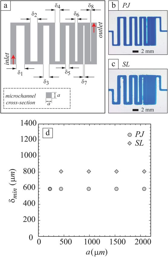
Biomicrofluidics                                                                                ARTICLE            scitation.org/journal/bmf

          Replica molding and soft lithography remain arguably one of        microchannels.35–45 Currently, there is no consensus on the best
    the most popular techniques for the fabrication of microchannels,        3D printing technique for fabricating molds for replicating PDMS
    especially in academic settings for research. Conventional soft          microchannels, especially with regard to fabricating molds for 3D
    lithography using cleanroom facilities mostly produces planar,           microchannels. Given that there are many readily available con-
    two-dimensional (2D) microchannels. Herein, we define planar,            sumer 3D printers in the market, there is a need for the careful
    2D microchannels as those having uniform height and rectangular          evaluation of 3D printers for their suitability to fabricate molds
    cross sections. We define non-planar, 3D microchannels as those          harboring microfeatures. While there are a few investigations into
    that have cross-sectional shapes other than rectangles and those         the suitability of 3D printers to fabricate an entire microchannel,55–58
    that have varying heights. A single-step photolithography results in     cross-platform studies to evaluate 3D printing of soft lithography
    replica with planar molds where all features have the same height.       molds remain lacking.59 In particular, there are limited quantitative
    Such planar geometries restrict the choice of fluids to be used, and     studies that focused on the surface roughness of 3D-printed mold
    additional surface modification is often required to change the          fabricated with different methods of 3D printing and the resultant
    wettability of channels.22,23 The fabrication of molds for micro-        bonding strength of PDMS replica with planar substrates.
    channels with arbitrary cross sections or varying heights by photo-      Furthermore, the feasibility to replicate planar and non-planar
    lithography requires a multi-step process that involves the manual       microchannels and closely packed microchannels with dimensional
    alignment of multiple masks.24,25 Some examples of replicated 3D         fidelity is worth investigating.
    microchannels have demonstrated the potential to use flows in 3D               In this paper, we evaluated PDMS replica from four common
    spaces. Mixing at a low Reynolds number can be enhanced by the           methods of 3D printing to contain non-planar microchannels and
    integration of grooves on the surface of microchannels.26 Stepped        closely packed microchannels. The replica used for the evaluation
    or terraced microchannels have been used in the robust, high             were obtained from four methods of 3D printing such as fused depo-
    throughput generation of droplets.27,28 Gradients in confinement         sition modeling (FDM), selective laser sintering (SLS), photo-
    have been exploited to generate and manipulate droplets in a facile      polymer inkjet printing (PJ), and stereolithography (SL). All these
    manner.29–31 Furthermore, 3D microchannels have been used to             printers were used to fabricate monolithic master molds to replicate
    manipulate cells.32,33 Despite these successes, fabricating non-         PDMS microchannels. The microstructures of the master molds
    planar, 3D microchannels by conventional soft lithography                (with varying heights and cross sections) were fabricated in an auto-
    demands intensive labor and time as it requires the fabrication of       mated and single attempt of 3D printing, followed by post-
    multiple masks with separate alignment and exposure for each.            processing. We quantified the surface roughness of the molds and
    Due to this limitation, the majority of PDMS microchannels fab-          the delamination pressure of the microchannels sealed with the glass
    ricated using conventional soft lithography have rectangular cross       substrates. The impact of surface roughness of the mold on the trans-
    sections, and they are quasi-2D in nature without variations in          parency of PDMS replica was also analyzed. Based on these measure-
    height. As such, there is much current interest in developing            ments, we filtered the printers that are suitable for fabricating molds
    facile methods to fabricate molds for 3D microchannels.                  for microfluidic devices. The replica from these suitable printers was
          3D printing has emerged as a promising candidate to fabricate      then tested for their accuracy to transfer the designed dimensions
    3D microchannels. 3D microchannels can easily manipulate multi-          and cross-sectional shapes from the molds. The study described in
    phase flows and help form templates with different spatial arrange-      this paper should provide useful guidelines to fabricate 3D micro-
    ments.34 In 3D printing, a computer-aided design (CAD) model of          channels using 3D printing and replica molding, which would allow
    a 3D object, decomposed into a sequence of 2D slices is used to          designing 3D flows in microchannels for various applications.
    fabricate the physical object in a layer-by-layer fashion. The
    process is automated, and it is suitable for the fabrication             RESULTS AND DISCUSSION
    of arbitrary 3D structures. 3D printing majorly contributes to micro-
    fluidics through the fabrication of molds for replication,35–45 entire   Research aim and approach
    devices,46–48 connectors/subunits for microfluidic devices,49–52 and           The aim of our study was to evaluate PDMS replica of
    partial units that can be integrated to form microchannels.53 Among      planar and non-planar channels obtained from molds printed by
    the different ways, 3D printing of molds for replication is derived      different types of 3D printers. Our evaluation included two
    from the conventional soft lithography where a master mold is            steps—(1) examination of surface roughness and bonding strength
    used to replicate microchannels. 3D printing of entire devices           and (2) testing the accuracy in dimensions of replicated microchan-
    provides a fast route to produce microfluidic chips. However,            nels. In the first step, the four molds from different printing mecha-
    evacuation of uncured resin52,54 from narrow channels and                nisms and their PDMS replica were examined for their surface
    removal of sacrificial support materials50 remains a challenge.          roughness (i.e., arithmetic mean roughness, Ra) and bonding strength
    Besides, SL printing of entire microchannels may suffer from             correspondingly. The measure of surface roughness and the resulting
    unintended photopolymerization of the channel region from the            delamination pressure were used to screen the printers not suitable
    subsequent illumination, which has been partially addressed by           for the fabrication of molds. Subsequently, we tested the accuracy of
    adding photoabsorbers to the resins. To circumvent the issues of         printed dimensions in the replicas from the selected printers. The
    clogging of material, researchers have adopted the fabrication of        dimensions of the printed channels (i.e., width and height) were mea-
    modular and partial units that can be post-assembled to form             sured and compared against the designed dimensions. The data were
    microfluidic devices. To this end, 3D printing of molds serves as a      analyzed in the form of deviation and error percentage, with the
    facile and general approach for the replication of PDMS                  mean and standard deviations.60–62

Biomicrofluidics 15, 024111 (2021); doi: 10.1063/5.0047497                                                                                   15, 024111-2
Published under license by AIP Publishing.
Biomicrofluidics ARTICLE scitation.org/journal/bmf
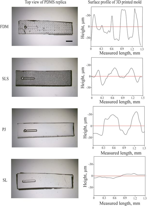
Surface roughness of the printed molds We found that molds printed using QiDi Tech 1 (FDM) and
Molds used for soft lithography must satisfy three essential EOS Formiga (SLS) printers were relatively rough and the micro-
criteria. First, the molds used should be physically robust. The sub- structures replicated in PDMS using these molds also retained
millimeter features should not be destroyed by the repeated casting rough surfaces. The photomicrographs of the top and cross-
sectional view of PDMS replica by the four printing methods visu-
of PDMS. Second, the molds should not chemically interfere with
ally depict the roughness of the molds (Fig. 1). Ra values (defined
the curing and removal of PDMS. Finally, the surfaces of the repli-
cated PDMS structures should be smooth enough to allow facile as arithmetical average roughness) of the four 3D-printed molds of
bonding with substrates. In our experiments, the molds printed by FDM, SLS, PJ, and SL are measured to be 16.7 (SD = 2.6), 3.3
QiDi Tech 1 (FDM) and EOS Formiga (SLS) 3D printers were used (SD = 0.3), 2.3 (SD = 0.4), and 1.4 μm (SD = 0.4 μm), respectively.
This roughness affected conformal contact of replicated PDMS
as printed, while the molds printed by Objet30 Prime (PJ) and
with glass substrates and thus inhibited chemical bonding via
Structo OrthoForm (SL) printers required washing and processing
as described in Materials and methods section. The photographs plasma oxidation. The surface profiles of the four 3D-printed
of molds printed by these printers are shown in Fig. S1 in the molds and the top view of PDMS microchannels are given (Fig. 2).
supplementary material. The surface roughness of PDMS replica was due to the surface
roughness of the mold, which was inherent to the mechanism of
printing. The rough surfaces of PDMS replica compromised the
optical transparency, which is an important requirement for the
PDMS devices.
FIG. 1. Photomicrographs of PDMS microstructures (wD = 500 μm,
hD = 500 μm) replicated from molds fabricated in four different techniques of 3D
printing. (a) and (b) Fused deposition modeling (FDM), (c) and (d) selective
laser sintering (SLS), (e) and (f ) photo-polymer inkjet printing (PJ), (g) and (h)
stereolithography (SL). (a), (c), (e), and (g) Photomicrographs showing the top
view of microstructures replicated in PDMS. (b), (d), (f ), and (h) FIG. 2. Photomicrographs of PDMS replica and plot showing the surface profile
Photomicrographs showing the cross-sectional view of the microstructures repli- of the four 3D-printed molds—fused deposition modeling (FDM), selective laser
cated in PDMS. sintering (SLS), photo-polymer inkjet printing (PJ), and stereolithography (SL).
Biomicrofluidics 15, 024111 (2021); doi: 10.1063/5.0047497 15, 024111-3
Published under license by AIP Publishing.Biomicrofluidics ARTICLE scitation.org/journal/bmf
PDMS casting/bonding from FDM-printed mold did not bond to the glass substrate owing
Molds fabricated by FDM and SLS printers were made of to the surface roughness created by imprints of the printed layers.
solid materials (e.g., filaments and particles), and PDMS was These layer imprints are influenced by the nozzle diameter of FDM
directly cast without any post-processing. PJ and SL printing are 3D printers. A commonly used nozzle is with a diameter of
400 μm. PDMS replica produced from SLS-printed molds were
based on the polymerization of photocurable liquid resins; it has
bonded to glass but the grainy texture on the surface affected trans-
been reported that the presence of the photoinitiators can interfere
with the polymerization of PDMS precursors cast on the molds parency. The applicability of SLS printing for the fabrication of
printed by SL and PJ.63 Removal of remaining photoinitiators and micromolds was also hampered by the difficulty to remove unsin-
unpolymerized monomers after 3D printing was, therefore, essen- tered particles from small cavities64 and the grainy surface finish.65
The grains on the surface of SLS-printed mold also tended to
tial for the successful replication. Heating, exposure to ultraviolet
adhere to PDMS replica during the replication. For SLS printers,
(UV) light, and washing with solvents are suggested by the
manufacturers as post-processing. Alternatively, the surface of the the use of small particles would, in principle, reduce the surface
mold can be rendered passive by coating it with an inert mate- roughness, but such printers are not widely available at this time;
rial.33,34,40,41 The post-processing used to treat the molds used in the sizes of particles of representative SLS printers are >50 μm
(Table S1 in the supplementary material). The use of fine particles
this study is described in Materials and methods section. The
for SLS printing is also reported to cause coagulation of particles,
PDMS replica obtained from the molds of four different printers
(FDM, SLS, PJ, and SL) was then bonded to glass by plasma oxida- which were not suitable for the current application.66 Post-processing
tion. Ideally, the molds should be used in a similar way to those of FDM and SLS-printed parts was generally carried out by mechani-
fabricated with SU-8 and a silicon wafer to maintain the conve- cal (e.g., eroding, milling) and chemical (e.g., coating, dissolution)
treatments.67–71 Despite these successful demonstrations, however,
nience of soft lithography. We, therefore, did not explore other
we did not explore those options in this study because such treat-
methods of bonding such as the use of partially cured PDMS as a
sealant for our microchannels. The layer of partially cured PDMS ments might alter the shape and dimensions of microscale features.
might give rise to an additional height of the channels and also it The current study focused on the capability to use 3D micromolds
can clog the narrow channels. for the fabrication of microchannels without such treatments.
Bonding strength of PDMS replica Accuracy of 3D printing:Planar microchannels
The bonding strength of the replica obtained from each method We identified PJ and SL as suitable mechanisms of 3D print-
of 3D printing was confirmed by measuring the delamination pres- ing to fabricate molds for microchannels. We further tested the
sure. The replica from FDM-printed mold did not covalently bond accuracy of printing by measuring the dimensions of features
to the glass after plasma oxidation. The replica was readily detached printed by Objet30 Prime (PJ) and Structo OrthoForm (SL) 3D
from glass due to its surface roughness. Therefore, sealed PDMS printers. PJ and SL printers operate in different mechanisms.
channels (width × height × length = 900 μm × 900 μm × 1 cm) obtained 3D-printed models by PJ printer are influenced by the size of resin
from the other three printers (SLS, PJ, and SL) were taken for the droplets, space between the droplets, and spreading of resin, while
testing. Colored water was pumped into the channels using a 3D-printed models by a SL printer depend on the size of a pixel
pressure-driven fluid dispenser. The applied pressure was 50 kPa and curing time. Therefore, the same design input is expected to
and was increased in the increments of 25 kPa. PDMS replica generate different microstructures. To test the accuracy of dimen-
obtained from the mold printed by SLS printer failed at 50 kPa sions by these printers, we printed a 5 × 5 array of cuboid micro-
(characterized by delamination from the glass). At 150 kPa, PDMS structures. The microstructures were designed to have widths,
replica obtained from PJ printer started to leak from a single point. wD = 0.1, 0.3, 0.5, 0.7, and 0.9 mm and heights hD = 0.1, 0.3, 0.5,
This leakage occurred from a gap along a straight line (due to a 0.7, and 0.9 mm. We defined wD and hD as the widths and heights
positive feature of the mold). Such a linear gap may occur in the designed in CAD, respectively. Both Objet30 Prime (PJ) and
direction parallel to the movement of the nozzle of PJ printer. Structo OrthoForm (SL) fabricated structures as small as
PDMS replica from SL printer held the internal pressure up to hD = 0.1 mm (which was the smallest height we tested). This height
400 kPa; the leakage happened at 400 kPa at the interface between is more than the layer thickness of the printers. Structo OrthoForm
the tubing and PDMS. It has been reported that a PDMS replica (SL) was not able to print structures with wD = 0.1 mm [resolution
obtained from silicon molds sealed to glass by plasma oxidation (x × y) = 0.1 × 0.1 mm2] and the minimum printable width was
withheld the pressure in the range between 206 and 345 kPa.14 Our 0.3 mm. While Objet30 Prime (PJ) was able to print structures with
measurements suggested that the molds obtained from PJ and SL wD = 0.1 mm [resolution (x × y) = 0.042 × 0.042 mm2], the printed
printing allowed fabricating microchannels that handled pressures heights for these structures were less than the designed heights.
up to 125 and 375 kPa, respectively, which would be sufficient to use PDMS was cast on the microstructures, and cross sections of the
the devices for representative microfluidic experiments. replicated microstructures were imaged under a low magnification
These observations on the surface quality and bonding of inspection microscope. In this paper, we used PDMS replica to
PDMS replica suggested that the molds printed using FDM and measure the dimensions of the channels. The use of PDMS stamps
SLS printers were not suitable for replica molding. A high surface allowed slicing the channels to visualize the cross-sectional profile.
roughness resulted in poor bonding and delamination from the We note that PDMS replica generally expands laterally (i.e., x,
glass and a non-transparent surface impairing visualization. Replica y-directions) after the release from the mold due to its high
Biomicrofluidics 15, 024111 (2021); doi: 10.1063/5.0047497 15, 024111-4
Published under license by AIP Publishing.Biomicrofluidics ARTICLE scitation.org/journal/bmf
thermal expansion coefficient (300 × 10−6 1/K),72,73 which would
affect the dimension of the channels. The expansion was not prom-
inent in the current study, and we used PDMS replica to study the
dimensions of the channels. The maximum widths (wM) and
maximum heights (hM) of the replicated microstructures were
measured from the cross sections [Figs. 3(a) and 3(b)]. The data-
points of wM were obtained by averaging the measured width over
the range of design height (hD = 0.1, 0.3, 0.5, 0.7, and 0.9 mm)
[Fig. 3(c)]. Similarly, the data points of hM were obtained by taking
the average of measured height over the range of design width
(wD = 0.3, 0.5, 0.7, and 0.9 mm) [Fig. 3(d)]. These plots show the
systematic deviation between the design and printed dimensions of
the channel. The absolute percent error for the width and height
for a replica from SL-printed mold is calculated to be in the range
of 7%–20% and 2%–8% respectively. Similarly, the percent error
for a replica from PJ-printed mold is 31%–125% and 2%–7% for
the width and height, respectively.
This increase in the width of PDMS replica can be attributed
to the mechanism of printing employed by PJ printers. In PJ print-
ers, there is a time-lapse between the resin deposition by the
printer head and curing of the deposited resin by the UV lamp.
The time lag between deposition and curing allowed the resin to
reflow and spread.55,56,74 The spreading of resin on the build tray
resulted in the widening of the width. This shows a large deviation
between the designed and the printed widths of PJ printers
[Fig. 3(c)]. SL printers do not have a limitation concerning the
spreading of resin; the walls of SL-printed molds are relatively
straight (compared to PJ-printed molds); the slanted vertical walls
are due to the diffraction of the light illuminated to the photoresin.
For printers with similar specifications in lateral (x, y) resolutions,
SL printers should have better accuracy for printing than a PJ
printer in the lateral dimensions of printed structures.
Our characterizations demonstrated the printability of straight
channels using PJ and SL printers. It is worth mentioning that
these two printers are also capable of fabricating curved channels
(such as arcs and serpentine shapes). The minimum pixel dimen-
sions of SL and PJ printers used in this study were 50 and 42 μm;
the lateral dimensions of the printed features were increased by
∼100 and ∼250 μm for the same SL and PJ printers [Fig. 3(c)].
Both SL and PJ printers are based on liquid resins, and the surface
tension of the liquid resin would promote the formation of contin-
uous smooth edges rather than pixelated edges along the defined
curvature. The minimum curvature that can be printed would
depend on multiple factors including the type of resin, the printed
layer height, and the minimum pixel size, which is left for further
investigation. FIG. 3. (a, b) Cross-sectional view of PDMS microstructures replicated from molds
that were printed using Objet30 Prime (PJ) and Structo OrthoForm (SL). The photo-
micrographs show representative measurements of maximum width (wM) and height
Accuracy of 3D printing: Non-planar microchannels (hM). (c) The plot of the measured maximum width (wM) of PDMS microstructures
The design of a microfluidic device includes channels of against the designed width (wD). (d) The plot of the measured maximum height
(hM) of PDMS microstructures against the designed height (hD).
varying dimensions and geometries (straight and curved features).
In our work, we assessed the replica from suitable printers (PJ and
SL) for its ability to form both rectangular and non-rectangular
geometries. Various non-rectangular geometries comprising gradi- Prime (PJ) and Structo OrthoForm (SL). Subsequently, the printed
ents in height, curves, and slanted lines were designed, printed, and structures were replicated in PDMS. The cross sections of PDMS
replicated in PDMS to assess 3D printers. Microstructures with replicas were observed under a microscope. We observed that the
slopes varying from 1.4° to 21.8° were fabricated using Objet30 height of channels increased in discrete steps [Figs. 4(a) and 4(b)].
Biomicrofluidics 15, 024111 (2021); doi: 10.1063/5.0047497 15, 024111-5
Published under license by AIP Publishing.Biomicrofluidics ARTICLE scitation.org/journal/bmf
FIG. 4. (a) Stereomicroscopic images of sloped PDMS structures replicated
using Objet30 Prime (PJ). (b) Stereomicroscopic images of sloped PDMS struc-
tures replicated using Structo OrthoForm (SL). The samples were slightly tilted
away from a nominal side-view to give a 3D view. The discrete increase in
heights was evident in the photomicrographs. (c) The measured slope of the
microstructures, θM, plotted against the designed slope, θD.
Objet30 Prime (PJ) prints with a smaller layer height (28 μm) than
Structo OrthoForm (SL) which prints with a layer height of 50 μm. FIG. 5. (a), (d), (g), ( j), and (m) Design of microchannels of non-rectangular
The microstructures replicated from molds printed with Objet30 cross sections. (b), (e), (h), (k), and (n) Photomicrographs of the cross section
Prime had a relatively smooth increase in height. A smaller lateral of PDMS microchannels replicated from molds printed using Objet30 Prime
(x, y) resolution and vertical (z) resolution allows Objet30 Prime (PJ). (c), (f ), (i), (l), and (o) Photomicrographs of the cross section of PDMS
(PJ) to print sloped structures with better accuracy than Structo microchannels replicated from molds printed using Structo OrthoForm (SL).
OrthoForm (SL) [Fig. 4(c)].
It is also essential that 3D printers accurately reproduce the
design of the cross sections of microchannels. We qualitatively
studied the ability of these 3D printers to fabricate various shapes of suggested that the molds for microchannels with flat top surfaces,
cross sections of the channels: semi-circular, triangular, trapezoidal, and straight sidewalls were printed and replicated more accurately by
and stepped patterns. The microchannels were replicated in PDMS. SL printer than PJ printer. Microstructures with semi-circular and
Photomicrographs of the cross sections of the microchannels and the triangular shapes were not reproduced by either printer. The lateral
sketches of their original design are shown (Fig. 5). Our experiments resolutions of the used printers were greater than 100 μm. As a
Biomicrofluidics 15, 024111 (2021); doi: 10.1063/5.0047497 15, 024111-6
Published under license by AIP Publishing.Biomicrofluidics ARTICLE scitation.org/journal/bmf
result, these printers could not accurately fabricate the parts of the
CAD model with the lateral dimension approaching zero (e.g., a
vertex of a triangle). Despite the difference in the layer height for the
two printers, these differences can also be attributed to the mecha-
nism of printing. The smooth transition between the slopes and the
increase in the width of the structures printed by PJ printers are due
to the reflow and spreading of resin. This reflow of resin can be
visualized by the curved regions at the corners increased width of
the features. Such changes affect the accuracy of the cross-sectional
shape of the replicated features acquired from the mold printed in PJ
printers. While in SL printer, the layers are projected as discrete enti-
ties into the resin vat and the structures are formed over the build
plate. Since the resin is confined in a bath, there is no scope for the
spreading of the resin. Furthermore, the surface of the resin in the
bath remains flat. The shapes of microstructure replicated from
SL-printed mold, therefore, conformed relatively close to the design,
with vertical sidewalls and a flat top wall.
Fabrication of closely spaced microchannels
Many microfluidic applications require devices with a small
footprint. Herein, the ability to fabricate microfluidic devices with
minimal spacing between adjacent microchannels is crucial. To test
this capability, a microfluidic device with nine parallel microchan-
nels with identical square cross sections was designed and printed
(wd = hd = a). The spacing between adjacent microchannels (δ) was
varied from 1400 to 100 μm [Fig. 6(a)]. Five of such microfluidic
devices were replicated from the molds, each having the same
variation in the inter-channel spacing but with microchannels of
different sizes (a = 300, 500, 1000, 1500, and 2000 μm). Water with
a blue food dye was passed through the microchannels and
observed under a microscope to check for any cross-flow between
adjacent microchannels. The spacing was measured as the distance
between the edges of the adjacent microchannels. The smallest
inter-channel spacing required was determined as the one where
there was no cross-flow between adjacent microchannels through-
out the length. The minimum spacings were measured as discrete FIG. 6. (a) Schematic of the microfluidic device used to determine the minimum
data based on the design dimensions of the gaps. For the micro- spacing required between adjacent microchannels. In a given microfluidic
channels fabricated from 3D-printed molds using Objet30 Prime device, the inter-channel spacing (δ) was varied—δ1 = 1400 μm, δ2 = 1200 μm,
(PJ), the minimum spacing required between two adjacent micro- δ3 = 1000 μm, δ4 = 800 μm, δ5 = 600 μm, δ6 = 400 μm, δ7 = 200 μm, and
channels was 600 μm [Fig. 6(b)]. For the microchannels fabricated δ8 = 100 μm. (b) and (c) Photomicrographs of the microchannel with water
from 3D-printed molds using Structo OrthoForm (SL), the (colored with a food dye) flowing through them. PDMS microchannels were repli-
cated from molds 3D-printed using (b) photopolymer inkjet printing (PJ) and (c)
minimum spacing required between two adjacent microchannels stereolithography (SL). (d) The minimum inter-microchannel spacing required to
varied from 600 to 800 μm. The minimum distance required avoid crossflow between neighboring channels, plotted for microchannels of
between adjacent microchannels for the varying microchannel sizes different nominal sizes.
(a) is plotted [Fig. 6(c)]. With both 3D printers, the minimum
required spacing was greater than the smallest channel width that
can be printed.
In PJ printing, the spreading of the deposited resin can bridge overexposure of the resin in the gaps (i.e., the spaces between two
the positive features defining the microchannels, which causes structures) can cause unintended polymerization,75,76 which
closely spaced microchannels to become connected. The spreading resulted in the bridge between two adjacent microchannels. This
of resin in PJ printing is consistent, regardless of the width and consideration was consistent with our observation that the adjacent
height of the channels. Therefore, a constant gap (600 μm) was channels were likely to be merged when the channels were high;
required for the mold fabricated by PJ printer. In SL printing, the the higher number of exposures was required to create the larger
light is illuminated only to the features defining the microchannels, relief structures on the mold, and consequently, the gaps were
and the resin in the gaps between the positive features should likely to be filled by overexposure. The bridging of the gaps in SL
remain unpolymerized. In practice, however, we found that printers is subjected to light irradiation, time of exposure, and
Biomicrofluidics 15, 024111 (2021); doi: 10.1063/5.0047497 15, 024111-7
Published under license by AIP Publishing.Biomicrofluidics ARTICLE scitation.org/journal/bmf
reactivity of the resin. These parameters vary from printer to resolution of 3D printers (currently available consumer PJ and SL
printer. One of the plausible ways to limit this bridging between printers have a typical lateral resolution of 100 μm), emerging tech-
microchannels in SL printing is by adding appropriate photoab- nologies allow printing at improved resolutions.78,79 Most PJ print-
sorbers to minimize overexposure to the light. The use of resins ers remain as proprietary systems and the installation and
with light-absorbing properties improves the resolution of SL maintenance cost of PJ printers remains rather high. Due to the
printing.52 However, our finding also suggested the print resolu- availability of inexpensive projectors and laser sources, desktop SL
tion of the positive features (257 μm) was greater than that of the printers may be suitable for academic laboratories and educational
negative features (600 μm), indicating the challenges to create institutes.
multiple channels in proximity. In general, adequate characteri-
zation should be performed to fabricate the mold for closely CONCLUSIONS
packed microchannels using SL and PJ printers.
In this paper, we evaluated the suitability of PDMS replica
from four different 3D printing techniques for their fabrication of
Printer specification and printing mechanism microfluidic devices and dimensional fidelity. We evaluated 3D
Our experiments are based on a particular 3D printer of each printers and corresponding replica in two sequential steps. In the
type, and the outcomes of our study about the representative print- first step of evaluation on surface roughness, we found that repli-
ers are influenced by both the specification of the chosen printer cated channels from molds printed using FDM and SLS printers
and the inherent printing mechanism. This paper aims to highlight exhibited rough and non-transparent surfaces that were not suitable
the importance of the mechanisms of 3D printers for their perfor- for fabricating PDMS microchannels. In contrast, PDMS replica
mance to create molds suitable for microfluidics. Such consider- from molds of PJ and SL printers formed 3D microfluidic devices
ations allow us to make an informed guess for the performance of in a facile way and exhibited delamination strength comparable
each printer to create microfluidic molds. with PDMS replica fabricated using a silicon wafer patterned with
For instance, factors specific to the printer include the size of SU-8. We also found that fabrication of closely spaced channels
the nozzle in FDM, size of particles in SLS, time-lapse between was challenging with 3D printers and materials we investigated; the
resin deposition and UV curing in PJ, curing time, and the reactiv- minimum distances required to prevent merging between the adja-
ity of the materials in SL. By altering these factors, we can improve cent microchannels were 600 and 600–800 μm for PJ and SL print-
the surface quality of molds and the fidelity of replicated micro- ing, respectively. Our work highlighted that 3D printing offers a
channels. However, the use of solid materials in FDM and SLS convenient route to design and fabricate 3D microchannels via
printers, spreading of resin in PJ, and unintended curing of the replica molding, and such 3D microchannels have the potential to
resin in SL are inevitable factors attributed to the mechanism of tune flows in a manner that would be impossible in planar micro-
printing. Similarly, the layer height would affect the attainable channels. We believe that 3D printing of the molds offers a facile
width of the printed pattern. An increase in the layer height would route for the fabrication of 3D microchannels, and the manipula-
result in an increase in the channel width in PJ printers due to tion of flows in 3D microchannels opens up further opportunities
resin spreading, while the effects would be minimal in SL printers. for research and applications in microfluidics.
In terms of deviation between designed and printed features (both
lateral and cross-sectional dimensions), we observed that SL printer MATERIALS AND METHODS
produced less deviation from the design than PJ printer. This 3D printing of molds
observation is in accordance with previous studies on these print-
ers.59 While PJ printers produced features that deviated largely AutoCAD® 2016 (Autodesk, USA) was used to design the
from the designed features, it was reported that PJ printer is still molds, and the designs were exported as STL files. Four different
suitable for the fabrication of molds for complex and intricate pat- printers, one of each for four different 3D printing techniques,
terns such as small-angled structures, vias, thin membranes, and were tested.
rounded channels.37,77 The inherent semi-circular cross section of
PJ-based mold can be advantageous for the fabrication of well- Fused deposition modeling (FDM)
established components such as pneumatic valves. As for the post- QiDi Tech 1 FDM printer (Zhejiang QIDI Technology Co.,
processing of the mold, the removal of rubbery support of Ltd, Zhejiang, China) was used. The molds were printed using pol-
PJ-printed parts generally takes longer than the removal of residual ylactic acid (PLA) filament in 160-μm layers with a 400-μm nozzle.
resin from SL-printed parts. Alternative approaches such as fabri- The molds were dry and non-sticky and, therefore, used for subse-
cating open channels were employed for the ease of the removal of quent experiments without any further post-processing.
support from molds of PJ printer.77
In choosing one printing technique over the other, it is crucial
Selective laser sintering (SLS)
to identify the factors affecting the quality of the replicated features.
The surface quality of the molds and bonding strength of the chan- Formiga P100 SLS printer (EOS GmbH Electro Optical
nels can be improved by the use of industrial-grade printers. Systems, Krailling, Germany) was used. The molds were printed
Nevertheless, our study also suggested that the feasibility to apply using polyamide particles (average grain size 56 μm). The molds
desktop SL printers to create microchannels via replica molding. were dry and non-sticky and, therefore, used for subsequent experi-
While molded microfluidic devices are currently limited by the ments without any further post-processing.
Biomicrofluidics 15, 024111 (2021); doi: 10.1063/5.0047497 15, 024111-8
Published under license by AIP Publishing.Biomicrofluidics ARTICLE scitation.org/journal/bmf
Photo-polymer inkjet printing (PJ) brightness and contrast were adjusted. An “Auto Level” function
Objet30 Prime PJ printer (Stratasys Ltd, Rehovot, Israel) was was then employed to further enhance the photomicrographs.
used. The molds were printed using the proprietary resin Veroclear
in 28 μm layers. The molds were printed in a glossy mode. In the SUPPLEMENTARY MATERIAL
glossy mode, a layer of the support material is first printed, and See the supplementary material for more details on (1)
the part is printed on top of the support layer. After printing, the 3D-printed molds and (2) commercially available SLS printers.
support material was removed by rinsing thoroughly with water.
The washed molds still exhibited a sticky surface. They were soaked AUTHORS’ CONTRIBUTION
in de-ionized (DI) water for 2 h. The molds were subsequently
P.P. and S.V. contributed equally to the work. P.P., S.V., and
dried with compressed air and placed in an oven at 60 °C for 5 h.
M.H. planned the study. P.P. and S.V. performed the experiments
This post-processing was carried out to ensure that PDMS does not
and analyzed the data. P.S.D. and M.H. supervised the research.
stick to the molds during the replication.
P.P. and S.V. drafted the manuscript. P.P., S.V., P.S.D., and M.H.
edited the manuscript.
Stereolithography (SL)
Structo OrthoForm SL printer (Structo Pte. Ltd., Singapore) ACKNOWLEDGMENTS
was used. The molds were printed in 50 μm layers using the propri- P.P. acknowledges the SUTD-MIT postdoctoral fellowship
etary resin from Structo OrthoForm. After printing, the sticky program. S.V. acknowledges the President’s Graduate Fellowship
molds were thoroughly cleaned using isopropyl alcohol (IPA). The awarded by the Ministry of Education (MOE), Singapore. M.H.
cleaned molds were placed in a UV chamber for 10 min before acknowledges the Start-up Research Grant (No. SREP14088) and
subsequent experiments. Digital Manufacturing and Design (DManD) Center at Singapore
University of Technology and Design for allowing us to use equip-
Replication of microchannels in PDMS ment (No. RGDM1620403). The authors thank Reno A. L. Leon
PDMS base and curing agent (Sylgard 184, silicone elastomer for help with 3D printing molds using the Structo OrthoForm.
kit, Dow Corning, USA) were thoroughly mixed in a 10 to 1 weight The authors received 3D printed molds from Structo3D for
ratio. The mixture was degassed under vacuum until the air evaluation. The authors declare no competing interests.
bubbles were completely removed. The degassed mixture was
poured into 3D-printed molds, and the molds with PDMS were DATA AVAILABILITY
then placed in an oven set at 60 °C for at least 3 h. The molded The data that support the findings of this study are available
PDMS replicas were then peeled off gently from the masters. The within the article and its supplementary material.
PDMS replicas were then sealed to glass slides using air plasma
treatment (Harrick Plasma PDC 32G). REFERENCES
1
M. G. Roper, “Cellular analysis using microfluidics,” Anal. Chem. 88, 381–394
Metrology (2016).
2
L. Y. Yeo, H. C. Chang, P. P. Chan, and J. R. Friend, “Microfluidic devices for
PDMS replica obtained from 3D-printed molds were sectioned
bioapplications,” Small 7, 12–48 (2011).
across the channels. The sliced cross sections were observed under 3
E. K. Sackmann, A. L. Fulton, and D. J. Beebe, “The present and future role of
the microscope (MU500, Amscope, Irvine, CA, USA) to measure microfluidics in biomedical research,” Nature 507, 181–189 (2014).
the printed width, height, angle, and distance between the channels. 4
L. Kang, B. G. Chung, R. Langer, and A. Khademhosseini, “Microfluidics for
Four samples were used to calculate the error bar. The error bars drug discovery and development: From target selection to product lifecycle man-
represent the standard deviation. The surface roughness of the agement,” Drug Discov. Today 13, 1–13 (2008).
molds was measured using a Hirox digital microscope (Hirox, 5
R. L. Hartman, J. P. McMullen, and K. F. Jensen, “Deciding whether to go with
Tokyo, Japan). the flow: Evaluating the merits of flow reactors for synthesis,” Angew. Chem. Int.
Ed. 50, 7502–7519 (2011).
6
A. Abou-Hassan, O. Sandre, and V. Cabuil, “Microfluidics in inorganic chemis-
Measurement of bonding strength try,” Angew. Chem. Int. Ed. 49, 6268–6286 (2010).
7
PDMS channel of 900 × 900 μm2 cross section and a length of D. Liu, H. Zhang, F. Fontana, J. T. Hirvonen, and H. A. Santos,
1 cm was sealed to the glass slide via plasma oxidation (Harrick “Microfluidic-assisted fabrication of carriers for controlled drug delivery,” Lab
Chip 17, 1856–1883 (2017).
Plasma PDC 32G). A fluid dispenser (Musashi SHOTMASTER®/ 8
E. W. Young and D. J. Beebe, “Fundamentals of microfluidic cell culture in con-
SHOTmini® ΩX series, Musashi Engineering, Inc., Japan) was used trolled microenvironments,” Chem. Soc. Rev. 39, 1036–1048 (2010).
to provide the required pressure. All the devices were tested for 5 s 9
Z. Dai, Z. Guo, D. F. Fletcher, and B. S. Haynes, “Taylor flow heat transfer in
at a given pressure to check for leakage or delamination. microchannels—Unification of liquid–liquid and gas–liquid results,” Chem. Eng.
Sci. 138, 140–152 (2015).
Imaging
10
D. Dendukuri and P. S. Doyle, “The synthesis and assembly of polymeric
microparticles using microfluidics,” Adv. Mater. 21, 4071–4086 (2009).
Adobe Photoshop was used to enhance all photomicrographs. 11
S. E. McCalla and A. Tripathi, “Microfluidic reactors for diagnostics applica-
The photomicrographs were first converted to gray scale, and the tions,” Annu. Rev. Biomed. Eng. 13, 321–343 (2011).
Biomicrofluidics 15, 024111 (2021); doi: 10.1063/5.0047497 15, 024111-9
Published under license by AIP Publishing.Biomicrofluidics ARTICLE scitation.org/journal/bmf
12
D. E. Patabadige et al., “Micro total analysis systems: Fundamental advances 37
C. C. Glick et al., “Rapid assembly of multilayer microfluidic structures via
and applications,” Anal. Chem. 88, 320–338 (2016). 3D-printed transfer molding and bonding,” Microsyst. Nanoeng. 2, 16063
13
D. C. Duffy, J. C. McDonald, O. J. Schueller, and G. M. Whitesides, “Rapid (2016).
prototyping of microfluidic systems in poly (dimethylsiloxane),” Anal. Chem. 38
G. Comina, A. Suska, and D. Filippini, “PDMS lab-on-a-chip fabrication using
70, 4974–4984 (1998). 3D printed templates,” Lab Chip 14, 424–430 (2014).
14
J. C. McDonald et al., “Fabrication of microfluidic systems in poly (dimethylsi- 39
K. Kamei et al., “3D printing of soft lithography mold for rapid production of
loxane),” Electrophoresis 21, 27–40 (2000). polydimethylsiloxane-based microfluidic devices for cell stimulation with con-
15
K. Ren, J. Zhou, and H. Wu, “Materials for microfluidic chip fabrication,” centration gradients,” Biomed. Microdevices 17, 36 (2015).
Acc. Chem. Res. 46, 2396–2406 (2013). 40
A. Castedo, E. Mendoza, I. Angurell, and J. Llorca, “Silicone microreactors for
16
D. Dendukuri, D. C. Pregibon, J. Collins, T. A. Hatton, and P. S. Doyle, the photocatalytic generation of hydrogen,” Catal. Today 273, 106–111 (2016).
“Continuous-flow lithography for high-throughput microparticle synthesis,” Nat. 41
A. P. Saghati, J. S. Batra, J. Kameoka, and K. Entesari, “A microfluidically
Mater. 5, 365–369 (2006). reconfigurable dual-band slot antenna with a frequency coverage ratio of 3:1,”
17
M. T. Rahman et al., “Dynamically tunable nanoparticle engineering enabled IEEE Antennas Wirel. Propag. Lett. 15, 122–125 (2015).
by short contact-time microfluidic synthesis with a reactive gas,” RSC Adv. 3, 42
G. L. Coté, M. Robinson, H. Marks, and G. L. Coté, “Comparison of produc-
2897 (2013). tion methods of a spiral inertial microfluidic cell separation device,” Proc. SPIE
18
M. A. Unger, H.-P. Chou, T. Thorsen, A. Scherer, and S. R. Quake, 9715, 97151C (2016).
“Monolithic microfabricated valves and pumps by multilayer soft lithography,” 43
J. C. McDonald et al., “Prototyping of microfluidic devices in poly
Science 288, 113–116 (2000). (dimethylsiloxane) using solid-object printing,” Anal. Chem. 74, 1537–1545
19
J. A. Weaver, J. Melin, D. Stark, S. R. Quake, and M. A. Horowitz, “Static (2002).
control logic for microfluidic devices using pressure-gain valves,” Nat. Phys. 6, 44
P. H. King, G. Jones, H. Morgan, M. R. de Planque, and K. P. Zauner,
218–223 (2010). “Interdroplet bilayer arrays in millifluidic droplet traps from 3D-printed
20
N. S. Devaraju and M. A. Unger, “Pressure driven digital logic in PDMS based moulds,” Lab Chip 14, 722–729 (2014).
microfluidic devices fabricated by multilayer soft lithography,” Lab Chip 12, 45
A. O. Olanrewaju, A. Robillard, M. Dagher, and D. Juncker, “Autonomous
4809–4815 (2012). microfluidic capillaric circuits replicated from 3D-printed molds,” Lab Chip 16,
21
N. Bhattacharjee, C. Parra-Cabrera, Y. T. Kim, A. P. Kuo, and A. Folch, 3804–3814 (2016).
“Desktop-stereolithography 3D-printing of a poly (dimethylsiloxane)-based 46
A. I. Shallan, P. Smejkal, M. Corban, R. M. Guijt, and M. C. Breadmore,
material with Sylgard-184 properties,” Adv. Mater. 30, 1800001 (2018). “Cost-effective three-dimensional printing of visibly transparent microchips
22
A. Rotem, A. R. Abate, A. S. Utada, V. Van Steijn, and D. A. Weitz, “Drop for- within minutes,” Anal. Chem. 86, 3124–3130 (2014).
mation in non-planar microfluidic devices,” Lab Chip 12, 4263–4268 (2012). 47
L. Donvito et al., “Experimental validation of a simple, low-cost, T-junction
23
M. Hashimoto, R. Langer, and D. S. Kohane, “Benchtop fabrication of micro- droplet generator fabricated through 3D printing,” J. Micromech. Microeng. 25,
fluidic systems based on curable polymers with improved solvent compatibility,” 035013 (2015).
Lab Chip 13, 252–259 (2013). 48
J. M. Zhang, E. Q. Li, A. A. Aguirre-Pablo, and S. T. Thoroddsen, “A simple
24
J. R. Anderson et al., “Fabrication of topologically complex three-dimensional and low-cost fully 3D-printed non-planar emulsion generator,” RSC Adv. 6,
microfluidic systems in PDMS by rapid prototyping,” Anal. Chem. 72, 2793–2799 (2016).
3158–3164 (2000). 49
S. Vijayan and M. Hashimoto, “3D printed fittings and fluidic modules for
25
A. Mata, A. J. Fleischman, and S. Roy, “Fabrication of multi-layer SU-8 micro- customizable droplet generators,” RSC Adv. 9, 2822–2828 (2019).
structures,” J. Micromech. Microeng. 16, 276–284 (2006). 50
Q. Ji et al., “A modular microfluidic device via multimaterial 3D printing for
26
A. D. Stroock et al., “Chaotic mixer for microchannels,” Science 295, 647–651 emulsion generation,” Sci. Rep. 8, 1–11 (2018).
(2002). 51
Y. Morimoto, M. Kiyosawa, and S. Takeuchi, “Three-dimensional printed
27
C. Priest, S. Herminghaus, and R. Seemann, “Generation of monodisperse gel microfluidic modules for design changeable coaxial microfluidic devices,” Sens.
emulsions in a microfluidic device,” Appl. Phys. Lett. 88, 024106 (2006). Actuators B Chem. 274, 491–500 (2018).
28
S. Sugiura, M. Nakajima, S. Iwamoto, and M. Seki, “Interfacial tension driven 52
T. Ching, Y.-C. Toh, and M. Hashimoto, “Fabrication of complex 3D fluidic
monodispersed droplet formation from microfabricated channel array,” networks via modularized stereolithography,” Adv. Eng. Mater. 22, 1901109
Langmuir 17, 5562–5566 (2001). (2020).
29
R. Dangla, S. Lee, and C. N. Baroud, “Trapping microfluidic drops in wells of 53
T. Ching et al., “Fabrication of integrated microfluidic devices by direct ink
surface energy,” Phys. Rev. Lett. 107, 124501 (2011). writing (DIW) 3D printing,” Sens. Actuators B Chem. 297, 126609 (2019).
30
P. Abbyad, R. Dangla, A. Alexandrou, and C. N. Baroud, “Rails and anchors: 54
T. Femmer et al., “High-throughput generation of emulsions and microgels in
Guiding and trapping droplet microreactors in two dimensions,” Lab Chip 11, parallelized microfluidic drop-makers prepared by rapid prototyping,” ACS
813–821 (2011). Appl. Mater. Interfaces 7, 12635–12638 (2015).
31
R. Dangla, S. C. Kayi, and C. N. Baroud, “Droplet microfluidics driven by gra- 55
R. Walczak and K. Adamski, “Inkjet 3D printing of microfluidic structures—
dients of confinement,” Proc. Natl. Acad. Sci. U.S.A. 110, 853–858 (2013). On the selection of the printer towards printing your own microfluidic chips,”
32
D. Di Carlo, N. Aghdam, and L. P. Lee, “Single-cell enzyme concentrations, J. Micromech. Microeng. 25, 085013 (2015).
kinetics, and inhibition analysis using high-density hydrodynamic cell isolation 56
J. M. Lee, M. Zhang, and W. Y. Yeong, “Characterization and evaluation of 3D
arrays,” Anal. Chem. 78, 4925–4930 (2006). printed microfluidic chip for cell processing,” Microfluid. Nanofluid. 20, 5
33
A. M. Skelley, O. Kirak, H. Suh, R. Jaenisch, and J. Voldman, “Microfluidic (2016).
control of cell pairing and fusion,” Nat. Methods 6, 147–152 (2009). 57
A. K. Au, W. Lee, and A. Folch, “Mail-order microfluidics: Evaluation of ster-
34
P. Parthiban, P. S. Doyle, and M. Hashimoto, “Self-assembly of droplets in eolithography for the production of microfluidic devices,” Lab Chip 14,
three-dimensional microchannels,” Soft Matter 15, 4244–4254 (2019). 1294–1301 (2014).
35
A. Bonyár et al., “3D rapid prototyping technology (RPT) as a powerful tool 58
N. P. Macdonald et al., “Comparing microfluidic performance of three-
in microfluidic development,” Procedia Eng. 5, 291–294 (2010). dimensional (3D) printing platforms,” Anal. Chem. 89, 3858–3866 (2017).
36
A. Bonyár et al., “Characterization of rapid PDMS casting technique utilizing 59
N. Mohd Fuad, M. Carve, J. Kaslin, and D. Wlodkowic, “Characterization of
molding forms fabricated by 3D rapid prototyping technology (RPT),” J. Mater. 3D-printed moulds for soft lithography of millifluidic devices,” Micromachines
Form. 7, 189–196 (2014). 9, 116 (2018).
Biomicrofluidics 15, 024111 (2021); doi: 10.1063/5.0047497 15, 024111-10
Published under license by AIP Publishing.Biomicrofluidics ARTICLE scitation.org/journal/bmf
60
T. Brajlih, B. Valentan, J. Balic, and I. Drstvensek, “Speed and accuracy evalua- 70
L. M. Galantucci, F. Lavecchia, and G. Percoco, “Experimental study aiming to
tion of additive manufacturing machines,” Rapid Prototyp. J. 17, 64–75 (2011). enhance the surface finish of fused deposition modeled parts,” CIRP Ann. 58,
61
M. C. Yuen and R. K. Kramer, in 2016 International Manufacturing Science 189–192 (2009).
and Engineering Conference (American Society of Mechanical Engineers, 2016). 71
T. K. Nguyen and B.-K. Lee, “Post-processing of FDM parts to improve
62
O. D. Yirmibesoglu et al., in 2018 IEEE International Conference on Soft surface and thermal properties,” Rapid Prototyp. J. 24, 1091–1100 (2018).
Robotics (RoboSoft) (IEEE, 2018), pp. 295–302. 72
C.-S. Park, K.-I. Joo, S.-W. Kang, and H.-R. Kim, “A PDMS-coated optical
63
H. N. Chan et al., “Direct, one-step molding of 3D-printed structures for con- fiber Bragg grating sensor for enhancing temperature sensitivity,” J. Opt. Soc.
venient fabrication of truly 3D PDMS microfluidic chips,” Microfluid. Korea 15, 329–334 (2011).
Nanofluid. 19, 9–18 (2015). 73
C. Li et al., “A review of coating materials used to improve the performance of
64
A. K. Au, W. Huynh, L. F. Horowitz, and A. Folch, “3D-printed microfluidics,” optical fiber sensors,” Sensors 20, 4215 (2020).
Angew. Chem. Int. Ed. 55, 3862–3881 (2016). 74
Y. Hwang, O. H. Paydar, and R. N. Candler, “3D printed molds for non-
65
A. Mazzoli, “Selective laser sintering in biomedical engineering,” Med. Biol. planar PDMS microfluidic channels,” Sens. Actuator A Phys. 226, 137–142
Eng. Comput. 51, 245–256 (2013). (2015).
66
J.-P. Kruth, G. Levy, F. Klocke, and T. Childs, “Consolidation phenomena in 75
M. P. Lee et al., “Development of a 3D printer using scanning projection ster-
laser and powder-bed based layered manufacturing,” CIRP Ann. 56, 730–759 eolithography,” Sci. Rep. 5, 9875 (2015).
(2007). 76
Z. Wang, N. Martin, D. Hini, B. Mills, and K. Kim, “Rapid fabrication of mul-
67
See https://www.3dhubs.com/knowledge-base/post-processing-sls-printed- tilayer microfluidic devices using the liquid crystal display-based stereolithogra-
parts/#standard for post-processing of SL-printed models. phy 3D printing system,” 3D Print Addit. Manuf. 4, 156–164 (2017).
68
J. C. Brooks, K. I. Ford, D. H. Holder, M. D. Holtan, and C. J. Easley, 77
S. Knowlton et al., “3D-printed microfluidic chips with patterned, cell-laden
“Macro-to-micro interfacing to microfluidic channels using 3D-printed tem- hydrogel constructs,” Biofabrication 8, 025019 (2016).
plates: Application to time-resolved secretion sampling of endocrine tissue,” 78
M. Mao et al., “The emerging frontiers and applications of high-resolution 3D
Analyst 141, 5714–5721 (2016). printing,” Micromachines 8, 113 (2017).
69
N. Jayanth, P. Senthil, and C. Prakash, “Effect of chemical treatment on tensile 79
H. Gong, B. P. Bickham, A. T. Woolley, and G. P. Nordin, “Custom 3D printer
strength and surface roughness of 3D-printed ABS using the FDM process,” and resin for 18 μm × 20 μm microfluidic flow channels,” Lab Chip 17,
Virtual Phys. Prototyping 13, 155–163 (2018). 2899–2909 (2017).
Biomicrofluidics 15, 024111 (2021); doi: 10.1063/5.0047497 15, 024111-11
Published under license by AIP Publishing.You can also read