Experimental Steam Condensation Enhancement on Metal Foam Filled Heat Exchanger
←
→
Page content transcription
If your browser does not render page correctly, please read the page content below
Journal of Mechanical Engineering Research and Developments
ISSN: 1024-1752
CODEN: JERDFO
Vol. 44, No. 4, pp. 145-167
Published Year 2021

 Experimental Steam Condensation Enhancement on Metal Foam Filled Heat
 Exchanger
 Ali Ali Abdul-Sahib* and Ayser Muneer
 Department of Mechanical Engineering / Engineering College/ University of Baghdad

 *Corresponding Author Email: alisquare2@yahoo.com

ABSTRACT: A porous medium is a material consisting of a solid matrix including void spaces, either unconnected or
connected. Pores may include a variety of fluids such as water. The open celled metal foam can be used in heat energy
absorption, and flow diffusion. The high cost of the material generally limits its use to advanced technology and manufacturing.
Metal foams are used in compact heat exchangers to increase heat transfer at the cost of reduced pressure. It is obvious that
utilizing metal foam to enhance heat transfer characteristics of heat exchanger have great advances. Many researchers have
examined these characteristics experimentally, numerically or both, by varying PPI, and porosity of different metal foams. The
recent researches reveal no enough understanding of all aspects of experimental studies for the forced convection with phase
change in horizontal copper tubes partially filled with metal foam and without metal foam (plain tube). Therefore, this
experimental study presented to delve into the most important details that cause the apparent lack of understanding the process
of the heat transfer through these types of applications. Consequently, the present work aimed to add further knowledge in this
field, which is done through experimental investigation to check the effect of use of metal foam on the heat condensation. This
was performed by manufacturing a heat exchanger filled with metal foam, using the copper alloy material. The study for the
impact of the metallic foam on the convection and conduction heat transfer coefficients and condensation amount was carried
out experimentally using a respective mechanical setting.

KEYWORDS: Heat exchanger, Metal foam enhancement, Steam condensation

INTRODUCTION

The metal foams are brilliant inventive materials with overly promising applications, where their low material density,
lightweight, ratio of the high surface area to the volume, and their exceptional thermal and mechanical characteristics exhibit
a brilliant means of the thermal properties and performance improvement [1]. Despite, they increased pressure drop and
interfacial resistance, they have the potential to improve the heat transfer coefficient because of their unique characteristics.
The porous structure of metal foam has influential points in hydrodynamics and heat transfer phenomena [2]. The large heat
transfer area which leads to improve condensation performance by absorbing a high amount of thermal energy, thermal
boundary layer destruction by turbulent flow development due to foam surface structure and rigid structure with light structure
are quite reasons to utilize metal foam in heat exchangers, condensers and thermal energy systems manufacturing [3].

Metallic foam is growingly elaborating to be a material with diverse uses. While metallic foam with closed pores has already
be produced as a strong and rigid lightweight material, the open-cell foam diversity is suitable for many engineering
applications such as thermal implementations. These novel materials have been still rarely used in coolers or heat exchangers
because their manufacturing is still costly and their application little examined. Researchers at a lot of expertize firms,
altogether with specific companies, want to modify this issue. They are advancing the production techniques furtherly and
developing modern metallic foams, and are examining them in an active workout [4]. Consequently, they are supplying the
needed requirements for building robust and active coolers, connectors, heat exchangers with a porosity of up to 90 percent
make gases or liquids easily flow inside them, which permits transmitting of large rates of heat. This is due to the good
conductivity and large surface area of the advanced metallic foam. However, the fluid dynamic and metallic behavior of the
different metallic foam had not been adequately studied. Furthermore, the most obstacles to utilizing these materials in power
engineering applications is their high production costs.

 145
Experimental Steam Condensation Enhancement on Metal Foam Filled Heat Exchanger

Applying of open-cell metallic foam has been vastly growing according to its multiple unprecedented properties in different
applications, which include the automotive industry, electronics technology, and both aviation or aeronautical applications
among others [3]. The open porosity, low relative density, the large accessible surface area per unit volume, high thermal
conductivity of the edges of foamed cell, the ability to mix the cooling fluid, lightweight, and all make metal foam heat
exchangers efficient, compact. Even though this material is proven to be very promising, there is still needing to use of the
open-cell metallic foam although it requires extensive efforts to achieve a full characterization. In this work to inspect the
condensation amount through the foam and to assess related thermo-physical properties to check the suitability of applying
metal foam in fluid flow and heat transfer purposes to highlight its advantages and disadvantages for future work.

The effective thermal conductivity of a heat exchanger can be significantly increased when it is embedded in a thermally
conductive metal foam matrix [4]. Therefore, metal foams have found increasing use in thermal management. Their surface
area is much larger than regular finned heat sinks, making the available surface area for heat transfer attractive.

The quantity relative density is defined as the ratio between the density of the foam material to the density of the solid material.
At the same PPI (pores per inch), increasing the relative density increases the average Nusselt number. But this happens at the
expense of higher pimping power. The larger hole size creates a lesser pressure drop; hence, less pumping power. Therefore,
the relative density is more important than PPI [5].

Most heat exchanger investigations especially condensers focus on heat transfer enhancement by applying an internal structure
such as metal foam [6,7]. While other investigators studied the thermal properties of the metal foam and heat transfer confidence
within metal foam for simpler systems [8,9].

There are some investigations, which referenced to various efficient parameters: overall and individual heat transfer
coefficients, the performance of foam finned surface, normalized mean wall temperature, surface pumping power per area
density, and pressure drop, have been conducted experimentally with metal foams in a variety of porosities and pore densities
using air as the fluid medium to exhibit the forced convection in metallic foam duct of high porosity [10] Calmidi and Mahajan
(2002)], the effect of open-cell foam presence in highly compact heat exchanger [11], and the effect forced convection in metal
foams with variety of (PPI) and porosity ranging on samples of different heights [12, 13]. Good agreement was achieved in the
whole range of the variables studied, demonstrating that using the metal foam treatment was significant to the representation
of forced convection heat transfer in metal foams for the heat transfer most practical applications. Further, those investigations
found that the pressure drop and heat transfer coefficient are optimum in presence of open foam, and the trend in the energy
balance shows that as the air mass flow rate is increased, the problems like air leakage become more significant as compared
to they were at low air mass flow rates. Furthermore, there are significant parameters such geometries (porosity, pore density,
and foam core height) and operation conditions (air gravimetric flow rate and imposed heat flux) that influences the heat
transfer and momentum flow behaviors of these improved surfaces. Also, these investigations showed that the copper foams
exhibit higher heat transfer performance than aluminum foams based on high thermal conductivity.

Utilized forced convective heat transfer of a counter current flow heat exchanger with the presence of porous media
enhancement has been studied experimentally by [14]. This investigation showed that, increasing of the ratio of hot fluid flow
(inner pipe flow) rate to cold fluid flow (inner pipe flow) rate decreases the performance of heat exchanger. Because of higher
surface area and turbulent flow eddies inside bulk fluid. Adding porous media increases effectiveness of heat exchanger.

The influence of partially packed annular metal foam shell wet ability on condensation heat transfer of water steam flow in
tubes has been experimentally investigated by [15]. They examined effect of water vapor mass flow, the pores density of metal
foam and surface wet ability of metal foam on the characteristics of flow condensation heat transfer. They showed that, the
metal foam pipe achieves superior heat transfer action and minimum pressure drop as compared with those smooth pipes.
Further, they stated that, at the same inlet steam pressure and mass flow rate, with customized surface wettability, the heat
transfer coefficient in a metal foam tube of 10 PPI was upper than that in a metal foam pipe of 15 or 20 PPI, and the convection
heat transfer coefficient increases out of the rising of mass flow rate of vapor. Furthermore, they illustrated that the inclusive
evaluation directory of the metal foam pipe was much superior to that of an unprocessed metal foam pipe, which revealed that
the metal foams have practical applications in steam flow of condensation heat transfer characteristics.

The most effective parameters in condenser or heat transfer performance in heat exchangers for porous metal foam case was:
the fluid flow parameters which is flow rates and saturation pressure, heat transfer characteristics (physical properties) and
porous matrix characteristics (porosities and pores densities). Intended for condensation rate enhancement purposes, the present
work focused on effect of these parameters on the condenser heat exchanger by utilizing Copper metal foams.

 146
Experimental Steam Condensation Enhancement on Metal Foam Filled Heat Exchanger

EXPERIMENTAL APPARATUS AND METHODOLOGIES

The effects of heat flux, mass flux, and metal foam morphological parameters on condensation heat transfer and pressure drop
have been tested. This section reveals the detailed descriptions of the experimental facilities and the procedures employed in
this work. The preliminary design and construction, test section, and the test rig with final construction were performed at the
laboratories of University of Baghdad.

The present experimental work used to investigate the effect of metal foam and without metal foam inside horizontal pipe and
saturated temperature on the condensation rate of the condensed steam on the surface of a pipe kept at low temperature, average
heat transfer rate, dryness (vapor quality), pressure drop, and heat transfer coefficient and to compare the experimental work
data with the theoretical data.
EXPERIMENTAL APPARATUS
The whole system was divided into several subsystems. Plate (1) illustrates the photographically of the experimental set-up,
which consists of four major combinations are the test section, cold water loop, the steam generation loop, and steam
condensation phase setting.

 Plate 1. The experimental Set-up

 147
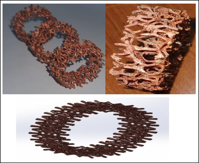
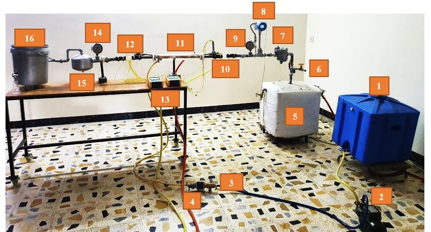
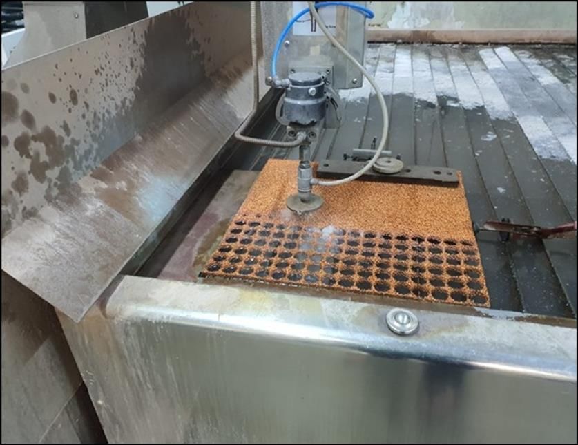
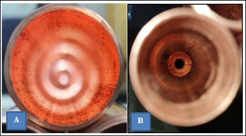
Experimental Steam Condensation Enhancement on Metal Foam Filled Heat Exchanger

The Test Section: The tubes that used in the experimental tests are made from copper alloy for the inner tube with length of
500 mm, and inner diameter of 28 mm, and wall thickness of 1 mm. The two main parts of the test section’s assembly, as
illustrated in Plate (2), are the copper tube filled partially with copper foam and the outer cooling tube. These two tubes are
demonstrated individually in the following sub-sections.

 Plate 2. The Test Section Assembly

The Copper Tube: Here the main test tube was partially filled with tubular copper alloy foam. To enhance the thermal
conductivity and gain smooth metal surfaces, the attached surfaces of tubes were well-grinded to remove the oxidation layers,
as shown in Plate (3). Depending on the known practical reality in traditional cutting techniques, such as welding or oxidizing
welding flames, it can be said that if these methods were applied, it can be caused damage to the outer surface of the metal
foam. Consequently, to keep the metal foam undeformed (preserve the edges of the metal foam from being bend or melt), those
foams were cut into tubular pieces using a water jet CNC machine. Plate (4) shows the cutting process used in this study. The
CNC machine was well programmed using NC Studio V10 to give precise pieces as shown in Plate (5). One test tube was
partially filled by Duocel metal foams (ERG Company, USA) manufactured in a porosity of 90%, and pores per inch (PPI) are
10. The metal foams were carefully cut to a cylindrical shape, by a suitable cutting method to prevent deforming its structure.
To ensure a perfect contact area between the outer surface of the metal foam and the inner surface of the test tube, when they
inserted using fit press inside the test tube, and also to reduce the thermal contact resistance, the diameter of the metal foam
samples was manufactured carefully to fit inside the inner diameter of the test tube. Plate (6) illustrates the configuration of a
sample of the metal foam's specimens. The properties of the metal foam partially filled in the test tubes; more details are
available Appendix (A). Plate (7A) shows the perfect insertion for the metal foam sample inside the test tubes. Plate (7B)
presents the plain tube that used in this study to compare the performance with the tube that was partially filled with metal
foam.

 148
Experimental Steam Condensation Enhancement on Metal Foam Filled Heat Exchanger

 Plate 3. Grinding Process for The Test Tubes

 Plate 4. Water jet CNC Cutting Machine

 149

Experimental Steam Condensation Enhancement on Metal Foam Filled Heat Exchanger

 Plate 5. NC Studio V10 CNC Program

 Plate 6. Metal foam’s sample

 150
Experimental Steam Condensation Enhancement on Metal Foam Filled Heat Exchanger

 Plate 7. Test Tubes; (A) partially filled with the metal foam, (B) plain tube
Cold Water Loop: The cooling water was circulated and pushed through the outer tube of the test rig, which is made of
transparent perspex with two accesses one used as the inlet cold water and the other as the outlet cold water. The outer cooling
tube in 66 mm and 68 mm of inner diameter and outer diameter, respectively. The ends of the cooling tube were fitted with
plastic seals to ensure tight-fitting to the inner tube and allow the thermocouples wires to be pulled out. In addition to the test
section, the water flow cooling system comprised the main tank (300-liter), water pump, and a turbine flow meter. The tank
was used to store water from the main water supply. The pump was used to be able to reach the specified mass flow rate of
cooling fluid. The cold water controlling a valve has been used after the pump to regulate the amount of cold water flowing
through the test section. The delivery pump circulated water around the test section and the outlet of the cold water was
discarded to drain, as the temperature of the cold-water outlet will be higher than the desired temperature of the cold water. To
gauge the flow rate of the cooling water, the turbine flow scale (meter) was used. The water pump specifications listed in Table
(1).

 Table 1. The water pump specifications
 Model MKF/1
 Quantity 30 L/min
 Head Max 10 m
 Voltage 220V-240V
 kW 0.37
 HP 0.5
 Current 2.5A
 Ingress Protection (IP) 44

Steam Generation Loop: The steam generation loop consists of a boiler tank, an electrical heater, water heater, a steam trap, a
steam meter, valves, and a vent valve. The boiler was made of stainless-steel tank dimensioned in 500 mm of width, 500 mm
in length, and 500 mm in height. The boiler tank insulated using a fiberglass wrapper. To ensure fast heating for the water
inside the boiler tank, the boiler equipped with heaters of total 12000W. For safety, a vent valve has been placed on top of the
boiler to ensure safe operation and avoid any high pressure of steam being trapped inside the boiler, as well as to regulate the
steam flow rate to the test section and discard any excess steam a bypass valve have been used. Vortex flowmeter used to
measure the inlet steam flow rate, steam temperature, and pressure while the inlet steam pressure to the test section was
measured by pressure gauge. The main valve regulates the steam flow rate inside the test rig. To allow fast steam generation
from the boiler, a water heater of 120-liter is connected to the boiler to preheat the inlet water to the boiler and the temperature
of the water heater heating element was controlled using thermostat on board of the heater in order to keep control on the

 151

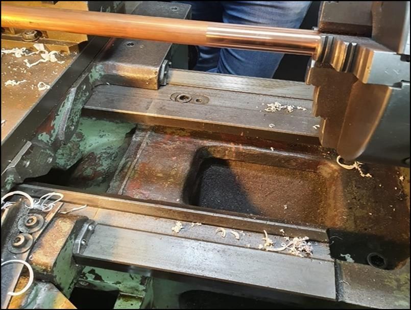
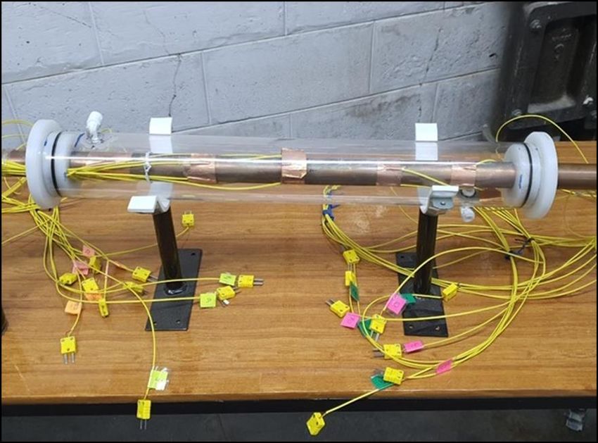
Experimental Steam Condensation Enhancement on Metal Foam Filled Heat Exchanger

maximum temperature of the hot water as we are to provide the preheated water at 80 0C. A pump is used to push the preheated
water into the boiler. Quartz glass tube is installed after the pressure gauges tapping at the inlet to observe the dry steam and
at the outlet of the test section to observe the condensed steam.

Steam Condensation Phase Setting: The steam condensation starts inside the test section. From the test section two fluids are
coming out the uncondensed steam and water as it can be seen from the transparent tube installed after the test section. the
pressure of the outlet from the test section is measured and the fluids are separated using steam separator where the condensed
water are collected at the bottom of the steam separator into a beaker and the uncondensed steam pass through a condenser
submerged in cold water and ice to ensure complete condensation.

Steam Trap and Separator: Steam separator and steam trap almost same in function. Both used to avoid the problem by water
residue in the steam.

Steam Trap: The steam separator is a device which separates water particle from steam. It used to increase the dryness fraction
(quality) of steam before it enters into turbine or engine. They usually employ a chamber to collect condensate and a drain
valve which activates automatically as per the pre-set water level in the chamber. Steam traps are used in such applications to
ensure that steam is not wasted and maintain the steam pressure. Inverted bucket steam trap is installed on the outlet of the
boiler, which have been obtained from the local market. Steam trap model “SARCO” is installed after the main valve to
discharge condensate while not permitting the escape of live steam.

Steam Separator: The main functions of the steam separator are separate water and steam. The principle of steam separator is
filter out condensate and non-condensate fluids. It is used when the pressure is not an important parameter to consider. Because
of density of steam is lighter than water make steam can be distributed easier than water. The water droplet which has higher
density will be separated and dropped from steam. Moisture will be removed.

Heat Isolation: To reduce heat lost from test rig and its accessories to the surrounding typical thermal insulation material of
fiber glass used to cover the test section and other parts of the test rig except for the condenser. The isolation made of two
layers which are; first layer is made of fiber glass with 2 cm thickness and it is thermal conductivity is 0.25 W/m. 0K. The
second layer is made of Aluminum-foil with (0.02) emissivity.

Temperature Measurement: Two units of calibrated twelve channel thermocouple data loggers’ model BTM-4208SD with SD
card and one unit of two channel thermocouple data logger’s model TM-925 were used to acquire and save the data along with
time information. The real-time data logger saves all the twelve temperature channels with a resolution of 0.1℃. The data
along with the time information were measured and recorded by the SD memory card and downloaded to Excel sheet. The K-
type thermocouples give a maximum temperature rating with varies from -200 ℃ to 1250℃. Each thermocouple alone was
connected to the data logger system. The calibration was done by subjecting each thermocouple to fixed temperature (distilled
water boiling at 100 ℃ and ice of temperature 0 ℃ at atmospheric pressure) calibration figures for the thermocouples are
available in appendix B. The locations are listed in Table (2). The test section has twenty thermocouples located in groups of
four in five locations on the inner tube of the test section. The thermocouples were attached to the inner tube surface by copper
high conductivity tape. Figure (1) illustrate the locations of the thermocouples on the inner tube. The thermocouples wires were
passed through two holes in the plastic sealing of the test section and through a piping junction where the thermocouples wires
were taken out from the top side and any excess cold water that might pass from the thermocouple’s holes will be directed into
drain, as shown in Plate (8). The thermocouples fabricated using thermocouple wire and the two ends of the wire were attached
to create the sensor. Welding the thermocouple tip to secure the sensor and get more accurate reading.

 152
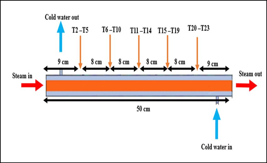
Experimental Steam Condensation Enhancement on Metal Foam Filled Heat Exchanger

 Plate 8. Thermocouple Welding

 Figure 1. Locations of The Thermocouples

 153
Experimental Steam Condensation Enhancement on Metal Foam Filled Heat Exchanger

 Table 2. List of the thermocouples
 Measuring location Thermocouples No.
 Boiler T1
 Inner tube surface T2 to T21
 Test section Outlet T22
 Cold water Tank T23
 Cold water Outlet T24

Flow rate measurement: The turbine flow meter was used in this work to measure cold water flow rate into the test section.
Table (3) presents flow meter specifications.
 Table 3. The turbine water flow meter specifications.
 Model K24
 Media Methanol fuel kerosene chemical liquid urea water
 Importers 1-inch internal thread
 Length 103mm
 Measurement accuracy ± 1%
 The repeatability ± 0.5%
 Maximum working pressure 20 bar
 Operating voltage 2.3-3.3Volts
 Battery type AAA
 Flow range 1-100L / min

Pressure Measurement: The pressure gauge which is a mechanical pressure scale used to measure the gauge pressures of
instruments (EN 837-4 model) with a range of 0 to 4 bar. To measure the pressure gradient along the length of the test section,
two pressure holes were placed at the inlet and outlet of the test tube in 0.5 inches of diameter and fixed on the test section.
Steam Measurement: The vortex flowmeter (JYLUGB-DN25 model) was used as an obstruction in the streamline of steam to
create a downstream vortex, which form an alternating low- and high-pressure zones that oscillate at particular frequencies that
directly proportional to the water steam velocity flow. The vortex was powered by a 24 VDC power supply. The inaccuracy of
the flow rate in most of the vortex meters is 0.5 -1%. The vortex flowmeter is a flow meter that uses the Karman vortex
principle [13] to measure steam, gas, and low viscosity liquids. When the fluid flows through the vortex generator placed
perpendicular to the flow direction of the measured medium, two rows of vortices are alternately generated on the rear sides
thereof, which is called a Karman vortex street. More details about the used vortex can be seen in Table (4).
 Table 4. Experimental parameters and ranges
 Parameter Range
 500
 Cold water (L/h) 1000
 1500
 Steam pressure 1 bar
 1.5
 2.5
 Steam flow rate (kg/h)
 3.5
 4.5

Preliminary Measurements: The copper foam is one type of porous media, it is needed to experimentally measure its main
properties to determine the exact conditions that experimental investigation proceeds with; effective thermal conductivity,
porosity, and permeability.

 154
Experimental Steam Condensation Enhancement on Metal Foam Filled Heat Exchanger

 Table 5. Vortex Specification
 Description Parameter
 Size DN25 (1 inch)
 Temperature Below 250 0C
 Pressure 1.6 MPa
 Connection Screw
 Material Stainless steel
 Power 24V
 Flow rate 0-200 kg/h
 Compensation Temperature and pressure

Experimental Methodologies
Investigation of Metallic Foam Porosity
The porosity (ϵ) is the significant property of metallic foam, which be contingent on pores volume and the total volume of the
metallic pieces that comprise foams. The taking a sample from copper foam with specific volume and inserted inside pipe. The
mass of the pipe with metal foam in dry configuration is measured. The pipe is than filled with water of the cooling , and the
pipe was lightly shaken to ensure that the cooling water filled the cavities of the pore network structures with the not context
of the air bubble that initiates by the trapped. The mass of the saturated configuration is measured. The mass difference inside
the pipe with the context of metallic foam before and after saturation is the mass of which filled the pore of the foamed media,
and when divided by the theoretical density of pure copper = 8933 / 3 [16].
Then porosity was found using the following equation:

 = =1− (1)

Investigation of Copper Foam Permeability
Fluid flow in porous media was described by Forchheimer [17] and Darcy [18]. The Forchheimer extended Darcy’s law shown
in equation (2) is extensively agreeable for incompressible and Newtonian fluid flow, steady-state, laminar, and unidirectional
pressure drop in a isotropic and homogeneous uniform foamed media [19].
 ∆
 = + 2 (2)
 √

The term ( ) represents the Darcy Number, while ( ) refers to Forchheimer number.
 √
Assuming that the effects of shear stress (viscosity) are negligible and the fluid flow is fully developed, the equation of
conservation of momentum can be calculated as
 ∆
 = + 2 (3)

When comparing the equation (3) with the equation (2), inertial coefficient and permeability respectively for each block of the
metallic foam can be established as:
 √
 = (4)

 = (5)

The K and C are the permeability and the inertial coefficient, respectively, of any block of the metallic foam, which were
experimentally estimated by gauging the drop of pressure across the test section at a different flow rate of vapor. To find the
inertial coefficient and permeability for every block of the metallic foam, the first constants (i.e., A and B) in the equations (4)
and (5) must be estimated using a second-order polynomial to fit the resulted curve.
Thermal Properties of Solid-Fluid Combined Media
Effective Thermal Conductivity

 155
Experimental Steam Condensation Enhancement on Metal Foam Filled Heat Exchanger

From the metal foam case the conductivity of effective must be calculated in order to find the effective heat transfer coefficient.
This effective conductivity is determined using the equation below [20]

 = (1 − ) + (6)

Where, is the conductivity of the soild and is the conductivity of the fluid.

Capacity of Mean Heat
For the saturated porous medium, the capacity of mean heat of fluid-solid combination can be estimated as the weighted
arithmetic mean of capacity of the fluid and solid heat, according to [4]

 ( ) = ( ) + (1 − )( ) (7)

where ( ) represents the mean heat capacity of media, ( ) refers to the fluid saturated heat capacity, and
( ) is the solid matrix heat capacity.

Operating and Experimental Procedure
Preliminary Preparation Procedure
The first step in the preliminary procedure is to turn on the water heater electrical switch, followed by switching on the boiler
after filling it with preheater water. Vortex flowmeter turned on and the flowmeter valve for cold water turned to open position
along with turning on the pump which will circulate cold water in the test section. Temperature data loggers are switched on
and check all the thermocouples are connected to it with no issues. Read the temperature of the cold water and make sure it is
in the desirable temperature
Rang of Experimental Values
In range of the variables used in the experimental tests are listed in Table (4), these values used for plain and enhanced tubes.
Start-up Procedure
To prevent the test rigs impact on the gained results, they were assembled and situated in a space far from environmental
impacts (e.g., direct sunlight radiations, the mechanical vibrations, fluctuations of the temperature, and the air wind).

Before the starting of the experimental measurements, and to ensure performing the tests very well it is necessary to check
there is no leakage in the test rig parts, especially surrounding the test section. Also, all connections of the instrument’s devices
must be checked.

The experimental procedure was performed by checking cold water temperature that meets the specify value and the inlet and
outlet water temperature are the same, and switching on the electrical heaters until the water start to boil and eventually steam
flow rate was adjusted to the required level by using the main valve and bypass valve. To reach steady-state conditions, at least
the apparatus was let up for 2 minutes.
Experimental Procedure
To carry out the experimental tests, a regulating valve was used for adjusting the required cold-water flow rate into the test
section; the thermocouple and pressure transducer readings were measured until they became constant using the data logger
apparatus, a final reading was recorded; the volume of the condensed steam that comes from the test section was estimated by
the graduated flask with time. This liquid amount of mass was measured based on its volume. Furthermore, this liquid mass
was subtracted from the rate of mass liquid flow at the inlet to generate vapor amount produced inside the system. Temperature
of the outlet cooling water was measured at the end of the experimental tests, the following readings was recorded; the readings
of the thermocouples in 0C, the reading of the pressure transducers in bar, the amount of vapor generated in kg/h. For the same
sample of tube foam, the water flow rate could be increased to cover another run.
Shut-down Procedure
To safely shut-down the test rig; the measurement devices (temperature data logger, vortex) turned off, and the collecting
beakers removed from their specified location, the power of the water heater and boiler heater turn off, the cold-water supply

 156
Experimental Steam Condensation Enhancement on Metal Foam Filled Heat Exchanger

motor turned off and the valve closed, the main valve shut off and bypass valve opened completely to allow any remaining
steam in the boiler to escape.
Experimental Work Data Reduction
The average heat flux q and total heat transfer rate Qc are calculated as follows [21]:

 = (8)

where the total heat transfer rate was obtained experimentally from
 = ( − ) (9)
The area of the condensate pipe surface can be found from the following equation
 = (10)
The average cooling water temperature, according to
 +
 = (11)
 2

For the flow condensation, the average convection heat transfer coefficient (h) can be estimated using

 ℎ= (12)
 −

where and are the average temperature of vapor and average wall temperature, respectively, which can be expressed as
follows:
 +
 = (13)
 2
 ∑
 = (14)

The local heat transfer coefficient of the condensing film was calculated

 ℎ = ( = 1,2, … … … 5) (15)
 −

Vapor quality
During the present experimental works, the steam flow and liquid flow were separated when they flowing-out through the test
section of condensation system. This mass fraction of vapor is expressed by the vapor quality (x) and to ensure the accuracy of
the experimental data, the test of thermal balance was executed. In that test, the experimental circumstances were set to make
sure that the quality of vapor at the inlet and outlet is 1 and 0, respectively.
The quality of vapor at the outlet (xo) and average quality of the vapor (x) are respectively defined as [21]
 3600
 0 = − (16)
 ×ℎ
and,
 + 0
 = (17)
 2

The vapor is condensed completely in experimental section. The vapor condensation heat transfer rate Qv is calculated as
follows [21]:
 [ℎ + ( − )]
 = (18)
 3600

Reynolds Number (ReK)
The Reynolds number can be defined, according to the length scale √ and the velocity at the test section inlet, as
 √
 = (19)

Prandtl Number (Pr)

 157
Experimental Steam Condensation Enhancement on Metal Foam Filled Heat Exchanger

For the Prandtl number, the dimensionless group can be defined as a function of the kinetic viscosity, and mean thermal
diffusivity of condensation [21]

 = ( ) (20)

 = (21)

The Nusselt Number (Nu)
Inside the enclosure of fluid saturated foamed media (i.e., porous material), the impact of fluid flow motion on the heat transfer,
is estimated by measuring the conduction referenced Nusselt number (Nu) [21].
 ℎ
 = = (22)
 ( − )
The Drop of Pressure
To develop the correlation for the flow condensation pressure drop, the technique of the whole multiplier of the liquid-phase
was utilized. In that technique, a drop of the two-phase flow can be expressed as follows [21]:
 = Δ , × (23)
Δpr,L can be described by the deformed equation of Ergun as written below

 2
 Δ , (1 − )2 (1 − ) 2
 = + (24)
 3 3
The (a) and (b) are the coefficients that gained empirically, which linked to the metal foam structure. The (asl) demonstrates
the specific surface area of the metallic foam. To calculate the structure of the metallic foam [21]:

 [1 − 0.971(1 − )0.5 ]
 = 4.867 (25)
 (1 − )0.5
 −1
 1 − 0.971(1 − )0.5
 =[ ( )] (26)
 0.6164(1 − )0.5
 1 − 0.971(1 − )0.5
 =[ (1 − )] (27)
 0.6164(1 − )0.5

According to the formula of Chisholm [21], the ( ) can be calculated as
 1
 = 1+ + (28)
 2

Uncertainty Analysis
The measurement system was made up of a number of components, each of which was subjected to individual accuracy; the
details are given in (Appendix B). Nusselt number is a function of (n) independents variable. The root mean square uncertainty
is calculating Nusselt number [22]

 2 2
 = √( ̇)2 + ( ℎ, ) + ( ℎ, ) + ( )2 + ( )2 (29)

The value of UNu, which represents Nusselt number uncertainty, was found to be 18 %
Repeatability
The experimental readings were taken in the period of August to September 2020. There is no doubt that, the environment

 158
Experimental Steam Condensation Enhancement on Metal Foam Filled Heat Exchanger

temperature affects slightly the final results in one form or another. A comparison was made between two reading sets taken
in the morning on one day when the environmental temperature was 22 oC and in the afternoon on another day when the
environment temperature was 28 oC, sample foam tube specification 10 PPI and 91% porosity. Comparison of results gives
approximately ± 3% as deviation percent for the temperature values.
RESULTS
Figures (2) and (3) shows comparing between the experimental results. Figure (A) shows the results of the steam quality against
the steam mass flow rate, while Figure (B) illustrates the results of convection heat transfer coefficient versus the steam mass
flow rate.

 Figure 2. Steam quality against the steam mass flow rate with and without using of metal foam.

 Figure 3. Quality of steam against the steam mass flow rate with and without using of metal foam

Figures (4) to (7) shows the heat transfer coefficient against the dimensionless axial position at 1.5, 2.5, 3.5 and 4.5 kg/h of
steam and 500 kg/h of cold water with and without using of metal foam.

 159
Experimental Steam Condensation Enhancement on Metal Foam Filled Heat Exchanger

Figure 4. Heat transfer coefficient against the dimensionless axial position at 1.5 kg/h of steam and 500 kg/h of cold water
 with and without using of metal foam.

Figure 5. Heat transfer coefficient against the dimensionless axial position at 2.5 kg/h of steam and 500 kg/h of cold water
 with and without using of metal foam.

 160
Experimental Steam Condensation Enhancement on Metal Foam Filled Heat Exchanger

Figure 6. Heat transfer coefficient against the dimensionless axial position at 3.5 kg/h of steam and 500 kg/h of cold water
 with and without using of metal foam.

Figure 7. Heat transfer coefficient against the dimensionless axial position at 4.5 kg/h of steam and 500 kg/h of cold water
 with and without using of metal foam.

 161
Experimental Steam Condensation Enhancement on Metal Foam Filled Heat Exchanger

Figure 8. Temperature distribution along the axial distance at 1.5 kg/h of steam and 500 kg/h of cold water without using of
 metal foam.

 Figure 9. Temperature distribution along the axial distance at 1.5 kg/h of steam and 500 kg/h of cold water with using of
 metal foam.

 162
Experimental Steam Condensation Enhancement on Metal Foam Filled Heat Exchanger

Figure 10. Temperature distribution along the axial distance at 2.5 kg/h of steam and 500 kg/h of cold water without using of
 metal foam.

 Figure 11. Temperature distribution along the axial distance at 2.5 kg/h of steam and 500 kg/h of cold water with using of
 metal foam.

 163
Experimental Steam Condensation Enhancement on Metal Foam Filled Heat Exchanger

Figure 12. Temperature distribution along the axial distance at 3.5 kg/h of steam and 500 kg/h of cold water without using of
 metal foam.

 Figure 13. Temperature distribution along the axial distance at 3.5 kg/h of steam and 500 kg/h of cold water with using of
 metal foam.

 164
Experimental Steam Condensation Enhancement on Metal Foam Filled Heat Exchanger

Figure 14. Temperature distribution along the axial distance at 4.5 kg/h of steam and 500 kg/h of cold water without using of
 metal foam.

 Figure 15. Temperature distribution along the axial distance at 4.5 kg/h of steam and 500 kg/h of cold water with using of
 metal foam.

Figures (8) to (14) refers to the temperature distribution along the axial distance at 1.5, 2.5, 3.5 and 4.5 kg/h of steam and 500
kg/h of cold water with and without using of metal foam.
DISCUSSION
In the case of very low porosity, the solid porous resistance (block) does not permit the fluid flow to go inside the sink of heat;
consequently there is no heat transfer by the convection will occur. While, at the metallic foam of very high values of porosity,

 165
Experimental Steam Condensation Enhancement on Metal Foam Filled Heat Exchanger

the conductivity of the porous material eaches the conducitvity of the fluid flow, this is much lower, which leads to minimize
the rate of the heat transfer [8]. The compromizing of large amount of the foamed material conductivity do not mean that the
high values of permeability. It just illustrates that the foamed materials have less resistance to the fluid that flows inside it [15].
Consequently, it could be stated that, there is a difference between the porous material permeability and pososity.

The experimental results revealed two validated and experimental models, which can be effectively used to optimize various
foamed heat exchanger for any known application by correlating heat transfer coefficient and pressure drop.
The experimental works were carried out at constant saturation temperature of 30 °C using the porous copper metal foam
(porosity of 0.93 and10 PPI).

To administrate the present thermal application, a novel experimental facilities that particularly organized to study flow of the
liquid and heat transfer characteristics, were used to gather the experimental results. The results relation to boiling flow heat
transfer and pressure drop within open-cell type metal foam at various heat flux, mass flow rate and vapor quality. The
outcomes represented the stair towards capabilities of the real heat transfer of the water vapor condensation. In addition, the
attractive heat transfer duties of metallic foam throughout the condensing flow and saturated heat transfer of the liquid.
REFERENCES
[1] A. A. Sertkaya, A. Ateş, K. Altinişik, K. Dđnçer., "Experimental and Numerical Analysis of one-Dimensional Heat
 Transfer on Open Cell Aluminum Foams." Gazi University Journal of Science, 2015

[2] A. H. N. Khalifa, I. M. Ali, and A. S. Hassoon, “Experimental Study the Performance of Aluminum Foams Condensers
 in the Vapor Compression Cycle,” Int. J. Curr. Eng. Technol., vol. 6, no. 2, pp. 600–605, 2016.

[3] ANSYS Inc., “ANSYS CFX-Solver Modeling Guide v14.0,” ANSYS CFX v14.0, vol. 15317, no. User’s Guide, p. 626,
 2011.

[4] A. Diani, K. K. Bodla, L. Rossetto, and S. V. Garimella, “Numerical investigation of pressure drop and heat transfer
 through reconstructed metal foams and comparison against experiments,” Int. J. Heat Mass Transf., vol. 88, pp. 508–
 515, 2015.

[5] Bonaccorsi, L., Proverbio, E. Powder Compaction Effect on Foaming Behavior of Uni-Axial Pressed PM
 Precursors. Advanced Engineering Materials. 8:9: 864–869, 2006. doi:10.1002/adem.200600082.

[6] B. Bidar, F. Shahraki, and D. Mohebbi-Kalhori, “3D numerical modelling of convective heat transfer through two-sided
 vertical channel symmetrically filled with metal foams,” Period. Polytech. Mech. Eng., vol. 60, no. 4, pp. 193–202,
 2016.

[7] E. Da Riva and D. Del Col, 2012 “Numerical Simulation of Laminar Liquid Film Condensation in a Horizontal Circular
 Minichannel” Journal of Heat Transfer, Vol. 134 / 051019-1.

[8] E. Bayraktar, O. Mierka, and S. Turek, “Benchmark computations of 3D laminar flow around a cylinder with CFX,
 OpenFOAM and FeatFlow,” Int. J. Comput. Sci. Eng., vol. 7, no. 3, pp. 253–266, 2012, doi:
 10.1504/IJCSE.2012.048245.

[9] G. B. Abadi, C. Moon, and K. C. Kim, “Experimental study on single-phase heat transfer and pressure drop of
 refrigerants in a plate heat exchanger with metal-foam-filled channels,” Appl. Therm. Eng., vol. 102, pp. 423–431, 2016.

[10] I. W. Maid, K. H. Hilal, and N. S. Lafta, “Experimentlal study of heat transfer enhancement using porous media in
 double tube heat exchanger,” Found. Tech. Educ., vol. 30, no. 1, pp. 44–59, 2017.

[11] Inayat, J. Schwerdtfeger, H. Freund, C. Körner, R. F. Singer, and W. Schwieger, “Periodic open-cell foams: Pressure
 drop measurements and modeling of an ideal tetrakaidecahedra packing,” Chem. Eng. Sci., vol. 66,

[12] J. Shi, G. Zheng, Z. Chen, and C. Dang, “International Journal of Heat and Mass Transfer Experimental study of flow
 condensation heat transfer in tubes partially filled with hydrophobic annular metal foam,” Int. J. Heat Mass Transf.,
 vol. 136, pp. 1265–1272, 2019.

 166
Experimental Steam Condensation Enhancement on Metal Foam Filled Heat Exchanger

[13] John Banhart. "What are cellular metals and metal foams?" the Wayback Machine, 2010.

[14] K. Nawaz, B. Jassie, D. Zhengshu, and A. M. Jacobi, “Experimental Studies to Evaluate the Use of Metal Foams in
 Highly Compact Air-Cooling Heat Exchangers,” Interntional Refrig. Air Cond. Conf., vol. 2502,

[15] L. Chen, “Navier-stokes equations for fluid dynamics,” pp. 1–10, 2014.

[16] M. Calmidi, “Transport phenomena in high porosity metal foams,” PhD Thesis, Univ. Color. Boulder, CO, USA, 1998.

[17] N. Dukhan, O. Bagci, M. Ozdemir, and L. Kavumacioglu, “Experimental Fully-Developed Thermal Convection for
 Non-Darcy Water Flow in Metal Foam,” J. Therm. Eng., vol. 2, no. 2, pp. 677–682, 2016.

[18] Shiomi M., Imagama S., Osakada K. and Matsumoto R. Fabrication of Aluminium foams from powder by hot extrusion
 and foaming. Journal of Materials Processing Technology. 210:9:1203–1208,
 2010.doi:10.1016/j.jmatprotec.2010.03.006.

[19] S. Mancin, C. Zilio, A. Diani, and L. Rossetto, “Air forced convection through metal foams: Experimental results and
 modeling,” Int. J. Heat Mass Transf., vol. 62, no. 1, pp. 112–123, 2013.

[20] T. P. de Carvalho, H. P. Morvan,D. M. Hargreaves2 · H. Oun and A. Kennedy , 2017” Pore-Scale Numerical
 Investigation of Pressure Drop Behavior Across Open-Cell Metal Foams” Transp Porous Med , 117:311–336.DOI
 10.1007/s11242-017-0835-y .

[21] V. V. Calmidi and R. L. Mahajan, “Forced Convection in High Porosity Metal Foams,” J. Heat Transfer, vol. 122, no.
 3, p. 557, 2002. pp. 1–10, 2010.

[22] W. T. Ji et al., “Film condensation heat transfer of R134a on single horizontal tube coated with open cell copper foam,”
 Appl. Therm. Eng., vol. 76, pp. 335–343, 2015.

 Steam Outlet

 167
You can also read