Exposed Linear Encoders - Heidenhain
←
→
Page content transcription
If your browser does not render page correctly, please read the page content below
Exposed
Linear Encoders

06/2021
Exposed linear encoders Contents
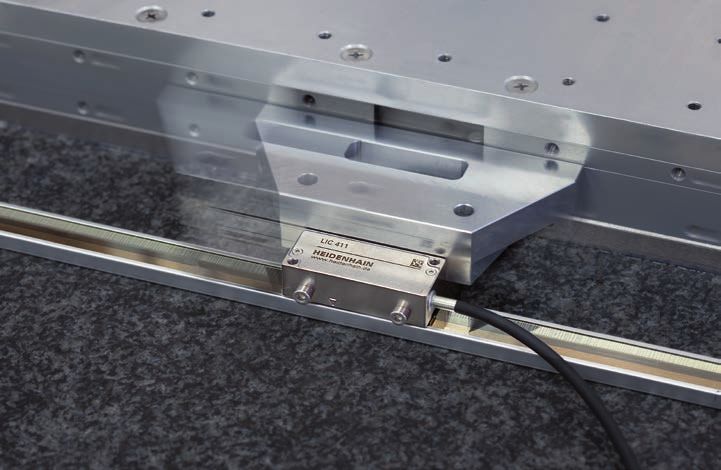
Linear encoders measure the position of Exposed linear encoders are used on Mechanical design Overview
linear axes without additional mechanical machines and equipment that require high Exposed linear encoders consist of a
transfer elements. A number of potential measuring accuracy. Typical applications scale or scale tape and a scanning head
error sources are thereby eliminated: include the following: that operate without mechanical contact. Exposed linear encoders 2
• Positioning error due to heat generation • Measuring and production equipment The scales of exposed linear encoders
in the recirculating ball screw in the semiconductor industry are fastened to a mounting surface. Selection guide 4
• Reversal error • PCB assembly machines High flatness of the mounting surface is
Technical characteristics
• Kinematic error through the ball-screw • Ultra-precision machines and devices thus an important requirement for the
pitch error such as diamond lathes for optical high accuracy of linear encoders.
components, facing lathes for magnetic Measuring principles 8
Linear encoders are therefore indispensable storage disks, and grinding machines
for machine tools on which high positioning for ferrite components Reliability 12
accuracy and a high machining rate are • High-accuracy machine tools
essential. • Measuring machines and comparators, Measuring accuracy 14
measuring microscopes, and other
precision measuring devices
Mechanical design types and mounting 17
• Direct drive motors General mechanical information 21
Functional safety 22
Specifications
For absolute position measurement LIC 4113, LIC 4193 24
LIC 4115, LIC 4195 26
LIC 4117, LIC 4197 28
LIC 4119, LIC 4199 30
LIC 4119FS 32
LIC 3117, LIC 3197 34
LIC 3119, LIC 3199 36
LIC 2117, LIC 2197 38
LIC 2119, LIC 2199 40
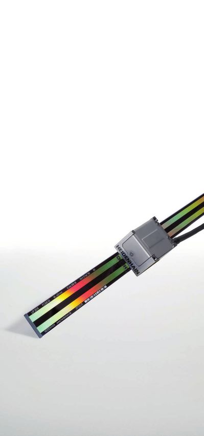
For high accuracy LIP 382 42
LIP 211, LIP 281, LIP 291 44
LIP 6071, LIP 6081 46
LIF 471, LIF 481 48
For high traversing speed LIDA 473, LIDA 483 50
LIDA 475, LIDA 485 52
LIDA 477, LIDA 487 54
Information on the following topics is LIDA 479, LIDA 489 56
available upon request or on the Internet
at www.heidenhain.com: LIDA 277, LIDA 287 58
• Angle encoders with integral bearing
• Modular angle encoders with optical Further information: LIDA 279, LIDA 289 60
scanning
For detailed descriptions of all available For two-coordinate measurement PP 281 R 62
• Modular angle encoders with magnetic
This brochure supersedes all previous interfaces, as well as general electrical
scanning
editions, which thereby become invalid. information, please refer to the Interfaces Electrical connection
• Rotary encoders
The basis for ordering from HEIDENHAIN of HEIDENHAIN Encoders brochure
• Encoders for servo drives
is always the brochure edition valid when (ID 1078628-xx).
• Linear encoders for numerically controlled Interfaces 64
the order is placed.
machine tools
For the required cables, please refer
• Interface electronics
Standards (ISO, EN, etc.) apply only to the Cables and Connectors brochure
Testing equipment and diagnostics 71
• HEIDENHAIN controls
where explicitly stated in the brochure. (ID 1206103-xx). Interface electronics 73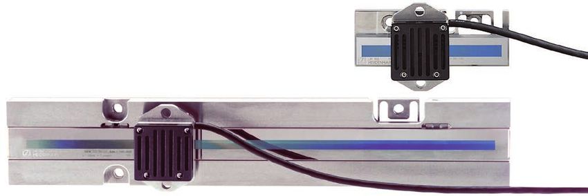
Selection guide
Absolute encoders
Absolute position measurement Baseline error Substrate and mounting Interpolation Measuring Interface Model Page
The LIC exposed linear encoders permit error length
absolute position measurement over long Accuracy Interval
traverse paths of up to 28 m at high grade
traversing speed.
1)
LIC 4100 ±1 µm ±0.275 µm/ Glass or glass ceramic scale, ±20 nm 240 mm to EnDat 2.2 LIC 4113 24
For very high accuracy ±3 µm 10 mm adhesively bonded to the 3040 mm LIC 4113V
Encoders for use in a vacuum ±5 µm mounting surface or fastened
environment with fixing clamps
5)
LIC 4193 LIC 41x3
HEIDENHAIN standard encoders are LIC 4193V
suitable for use in rough or fine vacuums.
Encoders used in high and ultrahigh ±5 µm ±0.750 µm/ Steel scale tape pulled through ±20 nm 140 mm to EnDat 2.2 LIC 4115 26
vacuums must meet special requirements. 50 mm aluminum extrusions and 28 440 mm
The design and materials used for such (typical) tensioned
5)
LIC 4195 LIC 41x5
encoders must be specifically tailored to
these conditions. For more information, ±3 µm ±0.750 µm/ Steel scale tape pulled through ±20 nm 240 mm to EnDat 2.2 LIC 4117 28
please refer to the Linear Encoders for ±5 µm2) 50 mm aluminum extrusions and secured 6040 mm
Vacuum Technology Technical Information ±15 µm2) (typical)
5)
LIC 4197
document.
LIC 41x7
±3 µm ±0.750 µm/ Steel scale tape, adhesively ±20 nm 70 mm to EnDat 2.2 LIC 4119 30
The LIC 4113V and LIC 4193V linear ±15 µm3) 50 mm bonded to mounting surface 1020 mm
encoders are specifically designed for use (typical)
5)
LIC 4199
in high vacuums. For more information,
please refer to the appropriate Product 70 mm to EnDat 2.2 LIC 4119 32
Information documents. 1820 mm
LIC 3100 ±15 µm3) ±0.750 µm/ Steel scale tape pulled through ±100 nm Up to EnDat 2.2 LIC 3117 34
For high accuracy 50 mm aluminum extrusions and fastened 10 000 mm LIC 31x9
5)
(typical) at center LIC 3197
Steel scale tape, adhesively EnDat 2.2 LIC 3119
bonded to mounting surface
5)
LIC 3199
LIC 2100 ±15 µm – Steel scale tape pulled through ±2 µm 120 mm to EnDat 2.2 LIC 2117 38
For simple mounting aluminum extrusions and secured 3020 mm LIC 21x7
5)
LIC 2197
±15 µm – Steel scale tape, adhesively ±2 µm 120 mm to EnDat 2.2 LIC 2119 40
bonded to mounting surface 3020 mm
5)
LIC 2199 LIC 21x9
1) 3)
Up to a measuring length (ML) of 1640 mm ±5 µm after linear length-error compensation in the subsequent electronics
2) 4)
For a measuring length (ML) of 1240 mm or greater With HEIDENHAIN interface electronics
5)
Fanuc Þi, Mitsubishi, Panasonic, Yaskawa
4 5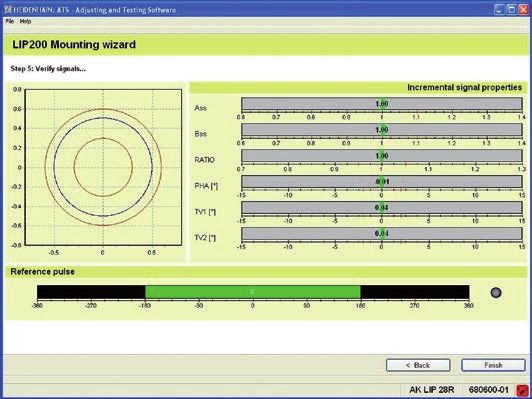
Selection guide
Incremental encoders
Very high accuracy Baseline error Substrate and mounting Interpolation Signal Measuring Interface Model Page
The LIP exposed linear encoders are error period length
characterized by their very small measuring Accuracy Interval
steps combined with extremely high grade1)
accuracy and repeatability. They utilize the
interferential scanning principle and feature LIP ±0.5 µm
3)
±0.075 µm/ Zerodur glass ceramic embedded ±0.01 nm 0.128 µm 70 mm to » 1 VPP LIP 382 42
an OPTODUR phase grating as their For very high accuracy 5 mm within a screw-on Invar carrier 270 mm LIP 382
measuring standard. The LIP 211 and
LIP 291 linear encoders output the position ±1 µm2) ±0.125 µm/ Scale made of Zerodur glass ±0.4 nm
7)
0.512 µm 20 mm to EnDat 2.2 LIP 211 44
information as a position value. For this to ±3 µm 5 mm ceramic, fastened with fixing 3040 mm
occur, the sinusoidal scanning signals are clamps » 1 VPP LIP 281
highly interpolated in the scanning head
and converted into a position value by the Fanuc Þi LIP 291
integrated counter function. As with all Mitsubishi
incremental encoders, the absolute
reference is established by means of ±1 µm5) ±0.175 µm/ Scale made of Zerodur glass – 4 µm 20 mm to « TTL LIP 6071 46 LIP 281
reference marks. ±3 µm 5 mm ceramic or glass, adhesively 3040 mm
bonded or fastened with fixing ±4 nm » 1 VPP LIP 6081
High accuracy clamps
The LIF exposed linear encoders utilize the
interferential scanning principle and LIF ±1 µm8) ±0.175 µm/ Scale made of Zerodur glass – 4 µm 70 mm to « TTL LIF 171 Product
possess a measuring standard made with For high accuracy ±3 µm 5 mm ceramic or glass, adhesively 3040 mm4) Infor-
the SUPRADUR process. They feature high bonded or fastened with fixing ±12 nm » 1 VPP LIF 181 mation
accuracy and repeatability, are particularly LIP 6081
clamps
easy to mount, and are equipped with limit
switches and homing tracks. The special ±1 µm5) ±0.225 µm/ Scale made of Zerodur glass – 4 µm 70 mm to « TTL LIF 471 48
version LIF 481 V can be used in high ±3 µm 5 mm ceramic or glass, adhesively 1640 mm
vacuums of up to 10–7 millibars (see bonded by means of PRECIMET ±12 nm » 1 VPP LIF 481
separate Product Information document). adhesive mounting film LIF 481V
High traversing speeds LIDA ±1 µm9) ±0.275 µm/ Scale made of glass ceramic or – 20 µm 240 mm to « TTL LIDA 473 50 LIF 481
The LIDA exposed linear encoders are For high traversing ±3 µm 10 mm glass, adhesively bonded to the 3040 mm
designed for high traversing speeds of up speeds and large ±5 µm mounting surface ±45 nm » 1 VPP LIDA 483
to 10 m/s. Their various mounting options measuring lengths
allow for particularly flexible deployment. ±5 µm ±0.750 µm/ Steel scale tape pulled through – 20 µm 140 mm to « TTL LIDA 475 52
Depending on the version, steel scale 50 mm aluminum extrusions and 30 040 mm
tapes, glass, or glass ceramic are used as (typical) tensioned ±45 nm » 1 VPP LIDA 485
the carriers for METALLUR gratings. They
also feature limit switches. ±3 µm2) ±0.750 µm/ Steel scale tape pulled through – 20 µm 240 mm to « TTL LIDA 477 54 LIDA 489
±5 µm 50 mm aluminum extrusions and secured 6040 mm
Two-coordinate measurement ±15 µm6) (typical) ±45 nm » 1 VPP LIDA 487
The measuring standard of the PP two-
coordinate encoder is an interferentially ±3 µm2) ±0.750 µm/ Steel scale tape, adhesively – 20 µm Up to « TTL LIDA 479 56
scanned planar phase grating ±15 µm6) 50 mm bonded to mounting surface 6000 mm4)
manufactured with the DIADUR process. (typical) ±45 nm » 1 VPP LIDA 489
Position measurement is thereby possible
within a plane. ±15 µm – Steel scale tape pulled through – 200 µm Up to « TTL LIDA 277 58 LIDA 287
aluminum extrusions and secured 10 000 mm4)
±2 µm » 1 VPP LIDA 287
±15 µm – Steel scale tape, adhesively – 200 µm Up to « TTL LIDA 279 60
bonded to mounting surface 10 000 mm4)
±2 µm » 1 VPP LIDA 289
7)
PP ±2 µm – Glass grid plate, secured with ±12 nm 4 µm Measuring » 1 VPP PP 281 62
For two-coordinate full-surface adhesive bond area:
measurement 68 x 68 mm4)
1) 5)
At an interval of 1 m or a measuring length < 1 m (accuracy grade) Only for Zerodur glass ceramic up to a measuring length of 1020 mm
2) 6)
Up to a measuring length of 1020 mm or 1040 mm ±5 µm after linear length-error compensation in the subsequent electronics
3) 7)
Higher accuracy grades upon request With HEIDENHAIN interface electronics
4) 8) PP 281
Other measuring lengths / measuring areas upon request Up to a measuring length of 1640 mm
9)
Only for Robax glass ceramic up to a measuring length of 1640 mm
6 7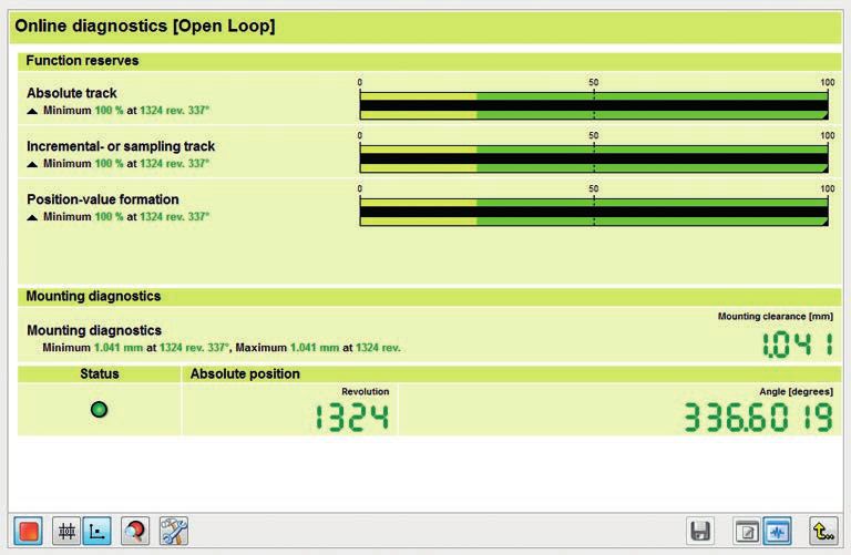
Measuring principles
Measuring standard Absolute measuring method Incremental measuring method
HEIDENHAIN encoders with optical With the absolute measuring method, the With the incremental measuring method, In the most unfavorable case, machine
scanning incorporate measuring standards position value is available immediately the graduation consists of a periodic movements over sizeable sections of the
consisting of periodic structures known upon switch-on of the encoder and can be grating structure. The position information measuring range may be necessary. To speed
as graduations. These graduations are requested at any time by the subsequent is obtained by counting the individual up and simplify such “reference runs,” many
applied to a carrier substrate made of glass electronics. There is no need to move the increments (measuring steps) from some HEIDENHAIN encoders feature distance-
or steel. For encoders with large measuring axes to find the reference position. The point of origin. Since an absolute reference coded reference marks—multiple reference
lengths, steel tape is used as the scale absolute position information is read from is required to ascertain positions, the marks that are individually spaced in
substrate. the graduation on the measuring measuring standard is provided with an accordance with a mathematical algorithm.
standard, which is designed as a serial additional track that bears a reference The subsequent electronics find the absolute
HEIDENHAIN manufactures the precision absolute code structure. A separate mark. The absolute position on the scale, reference after traversing two successive
graduations in the following specially incremental track is interpolated for the which is established by the reference mark, reference marks—thus after a traverse
developed, photolithographic processes: position value and, depending on the is assigned to exactly one signal period. path of only a few millimeters (see table
• METALLUR: contamination-tolerant interface version, is also used to generate Thus, before an absolute reference can be below).
graduation consisting of metal lines on an optional incremental signal. established or the most recently selected
gold; typical grating period: 20 μm reference point can be refound, this Encoders with distance-coded reference
• SUPRADUR phase grating: optically reference mark must first be traversed. marks are identified with a “C” following
three-dimensional, planar structure; the model designation (e.g., LIF 181 C).
particularly tolerant to contamination;
typical grating period: 8 μm and finer With distance-coded reference marks,
• OPTODUR phase grating: optically the absolute reference R is calculated
three-dimensional, planar structure with by counting the increments between two
particularly high reflectance; typical reference marks and by applying the
grating period: 2 μm and finer following formula:
• TITANID phase grating: exceptionally
robust, optically three-dimensional
structure with a high degree of P1 = (abs R–sgn R–1) x N + (sgn R–sgn D) x abs MRR
2 2
reflectance; typical grating period: 8 µm
and
Along with the very fine grating periods,
these processes permit high edge definition R = 2 x MRR–N
and excellent homogeneity of the graduation.
In combination with the photoelectric Where:
scanning method, these characteristics are P1 = Position of the first traversed N = Nominal increment between two
crucial for attaining high-quality output reference mark in signal periods fixed reference marks in signal
signals. periods (see table below)
abs = Absolute value
The master graduations are manufactured by D = Direction of traverse (+1 or –1).
HEIDENHAIN on custom-built, high-precision sgn = Algebraic sign function Traverse of scanning unit to the
dividing engines. (“+1” or “–1”) right (when properly installed)
equals +1
MRR = Number of signal periods between
the traversed reference marks
Graduation of an absolute linear encoder Graduations of incremental linear encoders
Signal Nominal increment Maximum
period N in signal periods traverse
LIF 1x1 C 4 µm 5000 20 mm
LIDA 4x3 C 20 µm 1000 20 mm
Schematic representation of a code structure with an additional Schematic representation of an incremental graduation with
incremental track (example from the LIC 411x) distance-coded reference marks (example from the LIDA 4x3 C)
8 9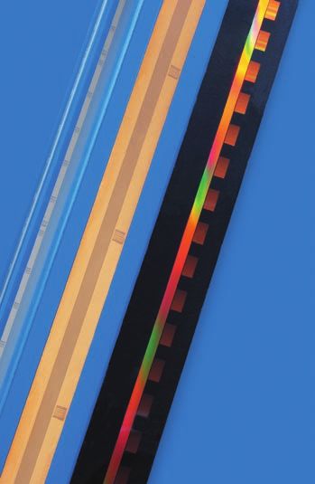
Photoelectric scanning
Most HEIDENHAIN encoders utilize the Imaging scanning principle Interferential scanning principle When there is relative motion between
photoelectric scanning principle. Photoelectric Put simply, the imaging scanning principle The sensor generates four nearly The interferential scanning principle exploits the scale and the scanning reticle, the
scanning is performed contact-free and uses projected-light signal generation: two sinusoidal current signals (I0°, I90°, I180°, the diffraction and interference of light on diffracted wavefronts undergo a phase
Signal period
thus does not induce wear. This method gratings with, for example, equal or similar and I270°), phase-shifted to each other finely divided gratings in order to produce shift: movement by the amount of one
360° elec.
detects even extremely fine graduation lines grating periods—the scale and the scanning by 90° elec. These scanning signals do the signals used to measure displacement. grating period shifts the positive first-order
down to a width of only a few micrometers reticle—are moved relative to each other. not initially exhibit symmetry about the diffraction wavefront by one wavelength in
and generates output signals with very The carrier material of the scanning reticle zero line. For this reason, the photocells A step grating is used as the measuring the positive direction, while the negative
small signal periods. is transparent, whereas the graduation of are connected in anti-parallel, thereby standard: reflective lines with a height of first-order diffraction wavefront is displaced
the measuring standard may likewise be producing two 90° elec. phase-shifted 0.2 µm are applied to a flat, reflective by one wavelength in the negative direction.
The finer the grating period of a measuring applied to a transparent material or to a output signals, I1 and I2, which are surface. In front of this is the scanning Since the two waves interfere with each
standard is, the greater the effect of reflective material. symmetrical about the zero line. reticle—a transparent phase grating with other upon exiting the phase grating, these
diffraction on photoelectric scanning. the same grating period as the scale. waves are shifted relative to each other by
HEIDENHAIN linear encoders employ two When parallel light passes through a In the X/Y representation on an two wavelengths. This results in two signal
scanning principles: grating structure, light and dark fields are oscilloscope, the signals form a When a light wave passes through the periods when there is relative motion of
projected at a certain interval. At this Lissajous figure. Ideal output signals scanning reticle, it is diffracted into three just one grating period.
• The imaging scanning principle for location there is an index grating with the appear as a centered circle. Deviations partial waves of the orders +1, 0, and –1,
grating periods from 10 μm to 200 μm same or similar grating period. When the in the circular form and position are with nearly equal luminous intensity. The Interferential encoders use grating periods
• The interferential scanning principle for two gratings move relative to each other, caused by position errors and therefore waves are diffracted by the scale such that of, for example, 8 µm, 4 µm, and finer.
very fine grating periods of 4 µm and the incident light is modulated: If the gaps go directly into the result of measure most of the luminous intensity is found in Their scanning signals are largely free of
smaller are aligned, light passes through. If the ment. The size of the circle, which the reflected diffraction orders +1 and –1. harmonics and can be highly interpolated.
lines of one grating coincide with the gaps corresponds to the amplitude of the These partial waves meet again at the phase These encoders are therefore especially
of the other, no light passes through. output signal, can vary within certain grating of the scanning reticle, where they well-suited for small measuring steps and
Photocells convert these light fluctuations limits without influencing the are diffracted again and interfere. This high accuracy. They nevertheless feature
into electrical signals. The specially structured measuring accuracy. produces essentially three waves that leave workable mounting tolerances.
grating of the scanning reticle filters the the scanning reticle at different angles.
light to generate nearly sinusoidal output Photocells convert these alternating light The LIP, LIF, and PP linear encoders use the
signals. The smaller the grating period of intensities into electrical signals. interferential scanning principle.
the grating structure is, the closer and
more tightly toleranced the gap must be
between the scanning reticle and the scale.
In encoders that use the imaging scanning
principle, workable mounting tolerances
are attainable starting at a minimum grating
period of 10 μm.
The LIC and LIDA linear encoders use the
imaging scanning principle.
90°
Phase shift
elec.
X/Y representation of the output signals
Structured Orders of diffraction
Scale Window detector –1 0 +1
Scale Scale graduation with
DIADUR phase grating
Condenser lens LED light
source
Scanning reticle
Condenser lens
Grating period
Index grating
LED light source Scanning reticle:
Photocells
transparent phase grating
Photoelectric scanning in accordance with the imaging principle with a steel scale and single-field Photoelectric scanning in accordance with the interferential measuring principle and single-field scanning
scanning (LIDA 400)
10 11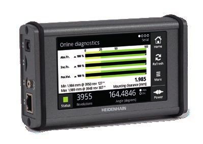
Reliability
Exposed linear encoders from HEIDENHAIN Durable measuring standards OPTODUR
are optimized for use on fast, precise By nature of their design, the measuring SUPRADUR
machines. Despite their exposed mechanical standards of exposed linear encoders are Reflective layer
design, these encoders are highly insensitive less protected from their environment. For
to contamination, ensure high long-term this reason, HEIDENHAIN always uses
stability, and are quickly and easily tough graduations manufactured in special Transparent
mounted. processes. layer
Lower sensitivity to contamination In the OPTODUR and SUPRADUR pro-
Both the high quality of the grating and the cesses, a transparent layer is first applied
Reflective
scanning method are responsible for the onto the reflective primary layer. For creating primary layer
accuracy and reliability of linear encoders. an optically three-dimensional phase grating,
Exposed linear encoders from HEIDENHAIN an extremely thin, hard chromium layer is Substrate
employ single-field scanning, in which a applied at a thickness of only a few nano-
single large scanning field is used to gener- meters. The graduations for the imaging
ate the scanning signals. Local contamination scanning principle exhibit a similar design
on the measuring standard (e.g., fingerprints and are manufactured in the METALLUR
from the mounting process or oil residues process. A reflective gold layer is covered METALLUR
from guideways) has only a slight influence with a thin layer of glass. On it are chromium
Semitransparent
on the light intensity of the signal compo- lines acting as absorbers. Since they are layer
nents and thus on the scanning signals. only several nanometers thick, these lines
Transparent
Although this contamination does cause a are semitransparent. Measuring standards
layer
change in the amplitude of the output sig- with OPTODUR, SUPRADUR, or METALLUR
nals, their offset and phase position remain graduations have proven to be particularly
unaffected. The signals remain highly inter- robust and insensitive to contamination
polable, and the position error within one because the low height of their structure
signal period remains small. Fingerprint Wire Oil1) Oil2) leaves practically no surface for dust, dirt,
or water particles to accumulate.
The large scanning field further reduces
1.2
Signal in VPP
the sensitivity to contamination. Depending Workable mounting tolerances
on the nature of the contamination, this 1.0 Very small signal periods usually come Reflective
feature can even prevent encoder failure. 0.8 with very narrow mounting tolerances for primary layer
This is particularly true of the LIDA 400 and the gap between the scanning head and
LIF 400, which feature a very large scanning 0.6 scale tape. This is the result of diffraction
surface area (14.5 mm2) relative to their 0.4 caused by the grating structures. Such
Signal amplitude in %
grating period. The same goes for the diffraction can lead to a signal attenuation of
0.2
LIC 4100, which has a scanning surface 50 % upon a gap change of only ±0.1 mm.
area of 15.5 mm2. Even in the case of 0 The interferential scanning principle and
contamination from printer’s ink, PCB dust, 0 40 60 80 100 120 innovative index gratings on encoders that
or drops of water or oil of up to 3 mm in Position in mm use the imaging principle allow for workable
diameter, these encoders continue to provide mounting tolerances despite tiny signal
Mounting tolerance
high-quality signals. The position error periods.
and noise in µm
1 (e.g., LIDA 403/409)
remains far below the values specified for
Interpolation error
the accuracy grade of the scale. The mounting tolerances of exposed linear
0 encoders from HEIDENHAIN have only a
The LIDA, LIF, and LIP 6000 encoders slight influence on the output signals. In
are equipped with the HSP 1.0 signal particular, the specified distance tolerance
processor ASIC from HEIDENHAIN. This –1 between the scale and scanning head = During mounting (without HSP 1.0)
Scanning gap in mm
ASIC continuously monitors the scanning (scanning gap) causes only a negligible = During operation (with HSP 1.0)
signal and compensates nearly completely 100 nm change in the signal amplitude. During
for fluctuations in signal amplitude. If the operation, the reliability and stability of the
50 nm
signal amplitude decreases as the result of signals are additionally improved by the
Signal amplitude in %
contamination on the scanning reticle or 0 HSP 1.0. The two diagrams illustrate the
measuring standard, the ASIC reacts by –50 nm correlation between the scanning gap and
increasing the LED current. The ensuing signal amplitude for the encoders of the
increase in LED light intensity barely raises –100 nm LIDA 400 and LIF 400 series.
the noise level, even in the case of strong
signal stabilization. As a result, contamination With HSP 1.0 signal processing ASIC
Without HSP 1.0 signal processing ASIC Mounting tolerance
has only a very slight influence on inter LIF 400
polation errors and the position noise. 1), 2) = Oil drops ¬ 2 mm half1) or fully2) covering the incremental track
Measuring standard with contamination and the associated signal amplitudes with conventional
scanning and scanning with the HSP 1.0 signal processing ASIC
= During mounting (without HSP 1.0) Scanning gap in mm
= During operation (with HSP 1.0)
12 13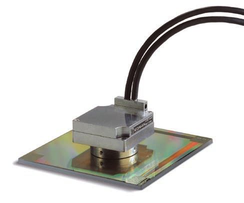
Measuring accuracy
The accuracy of the linear measurement Encoder-specific position error Accuracy of the interpolation Position noise Application-dependent Vibration
is mainly determined by Encoder-specific position error includes The accuracy of the interpolation is mainly Position noise is a random process leading position error To function properly, linear encoders must
• the quality of the graduation, • the accuracy of the measuring standard, influenced by to unpredictable position errors. The position In the case of encoders without integral not be continuously subjected to strong
• the quality of the graduation carrier, • the accuracy of the interpolation, and • the size of the signal period, values are grouped around an expected bearing, installing the encoder in the vibration. The best mounting surfaces are
• the quality of the scanning process, • the position noise. • the homogeneity and period definition value in the form of a frequency machine has a significant influence on the therefore solid and stable machine elements.
• the quality of the signal processing of the graduation, distribution. attainable overall accuracy beyond the Encoders should not be mounted on hollow
electronics, and by Accuracy of the measuring standard • the quality of scanning filter structures, specified encoder-specific position error. parts or with adapter blocks, etc.
• how the encoder is installed within The accuracy of the measuring standard is • the characteristics of the sensors, and The amount of position noise depends For assessment of the overall accuracy,
the machine. mainly determined by • the quality of the signal processing. on the signal processing bandwidths the individual application-dependent errors Influence of temperature
• the homogeneity and period definition necessary for forming the position values. must be measured and taken into account. In order to avoid temperature effects, the
These factors can be subdivided into of the graduation, The accuracy of the interpolation is It is ascertained within a defined time linear encoders should not be mounted in
encoder-specific position errors and • the alignment of the graduation on its ascertained with a serially produced interval and is stated as a product-specific Deformation of the graduation close proximity to heat sources.
application-dependent factors. For carrier, and measuring standard and is indicated by a RMS value. Errors due to a deformation of the graduation
assessment of the attainable system • the stability of the graduation carrier. typical maximum value u of the interpolation are not to be neglected. Such deformation
accuracy, all of the individual factors error. Encoders with an analog interface are In the speed control loop, position noise occurs when the measuring standard is
must be taken into account. The accuracy of the measuring standard is tested with a HEIDENHAIN electronic device influences the speed stability at low mounted on an uneven surface (e.g., a
indicated by the uncompensated maximum (e.g., EIB 741). The maximum values do traversing speeds. convex surface).
value of the baseline error. This accuracy not include position noise and are indicated
is ascertained under ideal conditions via in the specifications. Mounting location
measurement of the position errors with Poor mounting of linear encoders can
a serially produced scanning head. The The interpolation error already has an effect aggravate the effect of guideway error on
distance between the measuring points is at very low traversing speeds and during measuring accuracy. To keep the resulting
equivalent to the integer multiple of the repeated measurements. This error leads Abbé error as small as possible, the scale
signal period. As a result, interpolation to fluctuations in the traversing speed, should ideally be mounted to the machine
errors have no effect. particularly within the speed control loop. slide and at the height of the table. It is
important to ensure that the mounting
The accuracy grade a defines the upper limit surface is parallel to the machine guideway.
of the baseline error within any section
of up to one meter in length. For special
encoders, an additional baseline error is
stated for defined intervals of the measuring
standard.
Accuracy of the measuring standard Accuracy of the interpolation
Position noise
Position error
Position error
RMS
Position error
Baseline error
Interpolation
error
Signal level
Signal period
Time Frequency density
Position 360° elec.
Position
14 15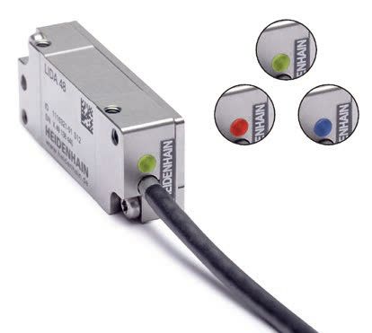
Mechanical design types and mounting
Calibration chart Linear scales
All HEIDENHAIN linear encoders are Exposed linear encoders are made up of
inspected for accuracy and proper functioning two separate components: the scanning
prior to shipping. head and linear scale or scale tape, which
are brought together solely over the
The accuracy of the linear encoders is machine guideway. For this reason, the
ascertained during traversing movements machine must be designed from the very Scale
in both directions. The number of measuring beginning to meet the following LIP 201
positions is selected such that not only the requirements:
long-range errors but also the position • The machine guideway must be
errors within a single signal period are very designed such that the scanning gap
accurately determined. LIP 201 R tolerances are complied with at the
ID 631000-13 location where the encoder is installed
The Quality Inspection Certificate Qualitätsprüf-Zertifikat Quality Inspection Certificate SN 44408260 (see Specifications)
DIN 55 350-18-4.2.2 DIN 55 350-18-4.2.2
confirms the specified accuracy grades of • The mounting surface of the scale must
each encoder. The calibration standards Positionsabweichung F [µm]
Position error F [µm]
meet the flatness requirements
ensure traceability to recognized national or • To facilitate adjustment of the scanning
international standards, such as required head to the scale, the scanning head Scale
by EN ISO 9001. should be fastened with a mounting LIP 6001
LIC 4003
bracket
For the LIP and PP encoder series, an
additional calibration chart documents the Scale versions
ascertained position error over the HEIDENHAIN provides the appropriate
measuring range. It also specifies the mea scale version for the given application and
suring parameters and the measurement Messposition PosE [mm] / Measured position PosE [mm]
accuracy requirements.
uncertainty.
Die Messkurve zeigt die Mittelwerte der Positionsabweichungen
aus Vorwärts- und Rückwärtsmessung.
The error curve shows the mean values of the position errors from
measurements in forward and backward direction. LIP 201 Scale
Temperature range Positionsabweichung F des Maßstab: F = PosM – PosE
PosM = Messposition der Messmaschine
Position error F of the scale: F = PosM – PosE
PosM = position measured by the measuring machine
LIP 6001 LIF 101 C
The linear encoders are calibrated at a refe PosE = Messposition des Maßstab PosE = position measured by the scale
LIC 4003
rence temperature of 20 °C. The position Maximale Positionsabweichung der Messkurve
innerhalb 670 mm ± 0,30 µm
Maximum position error of the error curve
within 670 mm ± 0.30 µm
The graduation carriers are fastened
error documented in the calibration chart is directly to the mounting surface with
valid at this temperature. Unsicherheit der Messmaschine
U95% = 0,040 µm + 0,400 ·10–6 · L (L = Länge des Messintervalls)
Uncertainty of measuring machine
U95% = 0.040 µm + 0.400 ·10–6 · L (L = measurement interval length)
clamps. A holder is used to define the
thermal fixed point.
Messparameter Measurement parameters
Messschritt 1000 µm Measurement step 1000 µm
Erster Referenzimpuls bei Messposition 335,0 mm First reference pulse at measured position 335.0 mm Accessories for the LIC 41x3 and LIP 60x1:
Relative Luftfeuchtigkeit max. 50 % Relative humidity max. 50 %
Fixing clamps ID 1176458-01 Scale
Holder for thermal LIP 6001
Dieser Maßstab wurde unter den strengen This scale has been manufactured and inspected in accordance with
HEIDENHAIN-Qualitätsnormen hergestellt und geprüft.
Die Positionsabweichung liegt bei einer Bezugstemperatur
the stringent quality standards of HEIDENHAIN.
The position error at a reference temperature of 20 °C lies within
fixed point ID 1176475-01 LIF 401
von 20 °C innerhalb der Genauigkeitsklasse ± 1,0 µm. the accuracy grade ± 1.0 µm.
Spacer shims ID 1176441-01 LIDA 403
Kalibriernormale Kalibrierzeichen Calibration standards Calibration references
Adhesive* ID 1180444-01 LIC 4003
Jod-stabilisierter He-Ne Laser 40151 PTB 11 Iodine-stabilized He-Ne Laser 40151 PTB 11
Wasser-Tripelpunktzelle
Gallium-Schmelzpunktzelle
61 PTB 10
62 PTB 10
Water triple point cell
Gallium melting point cell
61 PTB 10
62 PTB 10 Double-cartridge gun ID 1180450-01
Barometer A6590 D-K-15092-01-00 2012-12 Pressure gauge A6590 D-K-15092-01-00 2012-12
Luftfeuchtemessgerät 0230 DKD-K-30601 2012-11 Hygrometer 0230 DKD-K-30601 2012-11 Dispensing nozzles
and mixing tubes ID 1176444-01
28.01.2014
DR. JOHANNES HEIDENHAIN GmbH · 83301 Traunreut, Germany · www.heidenhain.de · Telefon: +49 8669 31-0 · Fax: +49 8669 5061 Prüfer/Inspected by K. Sommerauer
LIP 6001
LIF 401
LIDA 403
LIC 4003
The graduation carriers are adhesively
bonded directly to the mounting surface
with PRECIMET adhesive mounting film,
with even pressure applied by means of
a roller. A thermal fixed point can be
established at a location with epoxy
adhesive.
Accessory
Roller ID 276885-01
* Caution: no transport by air
(dangerous goods)
Trade name: 3M Scotch-Weld
Epoxy Adhesive DP-460 EG
16 17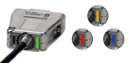
Mechanical design types and mounting
Scanning heads
LIC 41x5 Because exposed linear encoders are
Scale for LIC 4005, LIDA 405
LIDA 4x5 assembled on the machine, they must be LIP 200
Linear encoders of the LIC 41x5 and precisely adjusted after mounting. This
LIDA 4x5 series are specially designed for adjustment determines the final accuracy
long measuring lengths. They are mounted of the encoder. It is therefore advisable to
with scale carrier sections screwed onto design the machine such that this adjustment Spacer shim
the mounting surface or adhesively bonded is as easy and practical as possible, while
with PRECIMET adhesive mounting film. also ensuring the greatest possible degree
The single-piece steel scale tape is then of mounting stability.
pulled through the carrier sections, ten-
sioned as specified, and secured at its Mounting the LIP 2x1
ends to the machine base. The LIC 41x5 The LIP 2x can be fastened from the side
and LIDA 4x5 encoders thereby exhibit the as well as from above. The housing cover
same thermal behavior as that of the has a raised contact surface for the
mounting surface. thermal connection to ensure optimal
heat dissipation. The contact surface is
LIC 21x7 compressed against the mounting element LIP 6000
LIC 31x7 during mounting.
LIC 41x7
LIDA 2x7 Mounting the LIP 60x1
LIDA 4x7 The LIP 60x can be fastened from the side
Spacer shim
The encoders of these series are also as well as from above. When mounted
designed for long measuring lengths. from above, it is additionally possible to
The scale carrier sections are adhesively define a fixed center of rotation by inserting Option 1
bonded to the mounting surface with an alignment pin with ¬ 2 mm or ¬ 3 mm.
Option 2
PRECIMET adhesive mounting film; the This facilitates the alignment of the scanning
single-piece scale tape is pulled through, Scale for LIC 4007, LIC 2107, LIDA 207/407 head parallel to the scale. The alignment
and the midpoint is secured to the pin can be removed when mounting is
machine base. This mounting method completed.
allows the scale tape to expand freely at
both ends and ensures a defined thermal Mounting the LIF LIF 400
behavior. This scanning head features a centering
Spacer shim
collar with which the scanning head can be
Accessory for LIC 41x7, LIDA 4x7 rotated in the location hole of the angle
Mounting aid ID 373990-01 bracket and thereby aligned parallel to the
scale.
Mounting the LIC/LIDA
There are three options for mounting the
scanning head (see Dimensions). A spacer
shim makes it quite easy to set the gap
Mounting aid
(for LIC 41x7, LIDA 4x7) between the scanning head and the scale
or scale tape. It is helpful to fasten the
LIC/LIDA
scanning head from behind with a mounting
bracket. The scanning head can be very
Spacer shim
precisely adjusted through a hole in the
mounting bracket with the aid of a tool.
Adjustment
LIC 21x9 The gap between the scale and scanning
LIC 31x1 head is easily adjusted with the aid of a
LIC 41x9 Scale tape for LIC 4009, LIC 2109, LIDA 209/409 spacer shim.
LIDA 2x9
LIDA 4x9 The signals from the LIC, LIP 6000, and
The steel scale tape of the graduation is LIP 200 can be quickly and easily adjusted
adhesively bonded directly to the mounting with the aid of the PWM 20/21 adjustment
surface with PRECIMET adhesive mounting and testing package. For all other exposed
film, with pressure applied evenly with a linear encoders, the incremental and
roller. A ridge or aligning rail with a height reference mark signals are adjusted through
of 0.3 mm must be provided for the a slight rotation of the scanning head (for
horizontal alignment of the scale tape. the LIDA 400, it is possible with the aid of
a tool).
Accessories for versions with PRECIMET
Roller ID 276885-01 HEIDENHAIN offers the appropriate mea
Mounting aid, LIDA 2x9 ID 1070307-01 suring and testing devices as adjustment
3) Only with the LIDA 400
Mounting aid, LIC 21x9 ID 1070853-01 aids (see Testing equipment and diagnostics).
18 19General mechanical information
Signal-quality indicator
The LIDA, LIF, and LIP 6071 linear encoders Temperature range Protection (EN 60529) System tests
feature an integrated signal-quality indicator The operating temperature range states The scanning heads of exposed linear Encoders from HEIDENHAIN are usually
with a multicolor LED, permitting fast and the limits of ambient temperature within encoders feature the following degrees of integrated as components into complete
easy signal-quality checks during operation. which the specifications of the linear encoder protection: systems. Such applications require
are complied with. The storage tempera- comprehensive testing of the entire
This feature provides a number of benefits: ture range of –20 °C to +70 °C applies Scanning head Protection system, irrespective of the encoder’s
• Scanning-signal quality visualization when the unit remains in its packaging. specifications.
through a multicolor LED LIC IP67
• Continuous monitoring of incremental Thermal characteristics The specifications provided in this
signals over the entire measuring length The thermal behavior of the linear encoder LIDA IP40 brochure apply only to the encoder and
• Indication of reference-mark signal is an essential criterion for the working not to the entire system. Any operation
behavior accuracy of the machine. As a general rule, LIF IP50 of the encoder outside of the specified
• Quick signal-quality checks in the field the thermal behavior of the linear encoder range or outside of its proper and
without additional aids should match that of the workpiece or LIP 200 IP40 intended use is at the user’s own risk.
measured object. During temperature
The built-in signal-quality indicator permits changes, the linear encoder should expand LIP 300 IP50 In safety-related systems, the encoder’s
both a reliable assessment of the incremen- LIDA: signal-quality indicator in the scanning head or contract in a defined, reproducible LIP 6000 position value must be tested by the
tal signals and inspection of the reference manner. higher-level system after switch-on.
mark signal. The quality of the incremental PP IP50
signals is indicated by a range of colors The graduation carriers of HEIDENHAIN
permitting quite detailed signal-quality linear encoders (see Specifications) have
differentiation. The tolerance conformity differing coefficients of thermal expansion. The scales have no special protection.
of the reference mark signal is shown by This makes it possible to select the linear If the scales are exposed to contamination,
means of a pass/fail indicator. encoder with the thermal behavior best protective measures must be taken.
suited to the application.
Acceleration
Assembly
Parts subject to wear Linear encoders are subject to various
The steps and dimensions that must be
Encoders from HEIDENHAIN are designed types of acceleration during operation and
complied with during mounting are
for a long service life. Preventive maintenance mounting.
specified solely in the mounting instructions
is not required. However, they do contain • The indicated maximum values for
supplied with the device. All mounting-
components that are subject to wear, vibration apply to frequencies of 55 Hz
related information in this brochure is
depending on the application and how they to 2000 Hz (EN 60068-2-6). If, depending
therefore provisional and non-binding,
are deployed. This especially applies to on the application and the mounting
LED indicator for incremental signals and will not become the subject matter
cables that are subjected to frequent scenario, the permissible acceleration
LED color Quality of the of a contract.
flexing. values are exceeded (e.g., in the case
scanning signals LIF, LIP 6071: s ignal-quality indicator in the interface of resonances), then the encoder can
electronics Other parts subject to wear are the bearings become damaged. Comprehensive
Optimal in encoders with integral bearing, the radial testing of the entire system is
shaft seal rings in rotary encoders and therefore required
Good angle encoders, and the sealing lips on • The maximum permissible acceleration
sealed linear encoders. values (semi-sinusoidal shock) for shock
Acceptable and impact loads are valid for 11 ms
or 6 ms (EN 60068-2-27). Under no
Unsatisfactory circumstances should a hammer or
similar implement be used to adjust or
position the encoder
LED indicator for reference-mark-signal
(operating check)
When the reference mark is traversed,
the LED briefly lights up in red or blue:
Out of tolerance
Within tolerance
LED indicator for control margin
A flashing LED that turns dark every 2.5 sec-
onds indicates that the control margin of
the scanning ASIC is almost exhausted.
In this case, you should clean the measur- SUPRADUR, METALLUR, and OPTODUR
ing standard and the scanning window are registered trademarks of
of the scanning head in compliance with DR. JOHANNES HEIDENHAIN GmbH,
the relevant information in the mounting Traunreut, Germany.
instructions. The encoder may also need to Zerodur is a registered trademark of
be checked for correct mounting. Schott-Glaswerke, Mainz, Germany.
20 21Functional safety
With the absolute linear encoders of the The reliable transmission of the position is In addition to the data interface, the Material Angle bracket for scanning head Mounting surface
LIC 4100 series, HEIDENHAIN offers an based on two independently generated mechanical connection of the encoder to The material used for the mounting for measuring
ideal solution for position acquisition on absolute position values and on error bits the drive is also safety-relevant. In table D8 surfaces of the scanning head and standard
linear axes in safety-related applications. provided to the safe control. The functions of the standard for electrical drive systems, measuring standard must comply with
In conjunction with a safe control, the of the encoder can be used for numerous EN 61800-5-2, the loosening of the the specifications provided in the table. Material Steel Aluminum Steel,
encoders can be used as single-encoder safety functions of the complete system mechanical connection between the aluminum
systems in applications with control category as per EN 61800-5-2. encoder and the motor is listed as a fault Mounting temperature
SIL 2 (as per EN 61508) or performance that requires consideration. Since it cannot All information on screw connections is Tensile strength 600 N/mm2 220 N/mm2 Not applicable
level “d” (as per EN ISO 13849). The LIC 4100 linear encoder can provide a be guaranteed that the control will detect based on a mounting temperature of 15 °C Rm
safe, absolute position value at any time— such errors, fault exclusion for the to 35 °C.
including immediately after switch-on. loosening of the mechanical connection is Shear strength τB 390 N/mm2 130 N/mm2 Not applicable
Purely serial data transfer takes place via required in many cases. Mounting the scanning head
the bidirectional EnDat 2.2 interface. M2 screws as per ISO 4762 8.8 are to be Elastic modulus E 200 000 N/mm
2
70 000 N/mm2 Not applicable
Unless otherwise specified, HEIDENHAIN used for the mechanical fault exclusion to 215 000 N/mm2 to 75 000 N/mm2
encoders are designed for a service life of (included in delivery). A PWM20/21 and the
20 years (in accordance with ISO 13849). mounting wizard of the ATS software are Coefficient of 10 · 10–6 K–1 to 25 · 10–6 K–1 10 · 10–6 K–1 to
then used to check and optimize the thermal expansion 17 · 10–6 K–1 25 · 10–6 K–1
mounting. Þtherm
Mounting the scale tape
The steel scale tape of the graduation is
adhesively bonded directly to the mounting
surface with PRECIMET adhesive mounting
film, with pressure applied evenly with a
roller. The scale tape is additionally secured
Fault exclusion for the loosening of the Mounting and operating conditions by a screw (punched hole in scale tape).
mechanical connection This fault exclusion has been qualified for a The mounting aid (included in delivery)
The machine manufacturer is responsible wide range of encoder applications and is facilitates the symmetrical alignment of the
for the dimensioning of mechanical ensured for the operating conditions listed screw to the punched hole.
connections in a drive system. During the below.
mechanical design phase, the OEM will Note:
ideally consider the conditions within the The scanning head may be operated only
application. Verifying a safe connection, within the permissible mounting tolerances
however, is both cost- and time-intensive. and measuring length of the measuring
That’s why HEIDENHAIN has developed a standard.
type-examined mechanical fault exclusion
for the LIC 4100 series. Included in delivery:
Scanning head
• Fastener kit ID 1233536-01
(two M2x16 screws)
• Fastener kit ID 1233536-02
(two M2x25 screws)
Mechanical Fastening Safe position for the Confined parameters
3) • Spacer shim ID 578983-06
connection mechanical coupling
Scale
Scale Screw connection
1) 2)
±0.0 mm See specifications: • One screw ID 1233558-01
• Vibration • Mounting aid ID 1244387-02
Scanning head Mounting configurations I and II: • Shock
Screw connection:2) Accessories:
M2x25 ISO 4762 8.8 screws See mounting information: • Mounting wizard in ATS software
• Usable materials • Roller ID 276885-01
Mounting configuration III: • Mounting conditions
Screw connection:2)
M2x16 ISO 4762 8.8 screws
1)
A material bonding anti-rotation lock is to be used for the screw connections of the scale (mounting/servicing)
2)
Friction class B as per VDI 2230
3)
When compared with an LIC 4100 without functional safety
22 23LIC 4113, LIC 4193
Absolute linear encoders for measuring lengths of up to 3 m
• Measuring steps of down to 1 nm
• Glass or glass ceramic measuring standard
• Measuring standard secured with adhesive film or fixing clamps
• Consisting of a linear scale and scanning head (with straight or angled cable outlet)
• Version available for use in a high vacuum (see separate Product Information document)
Scale, clamped Linear scale LIC 4003
Measuring standard METALLUR grating on glass or glass ceramic
Coefficient of linear expansion* Þtherm 8 · 10–6 K–1 (glass)
Þtherm = (0 ±0.5) · 10–6 K–1 (Robax glass ceramic)
33.2
Accuracy grade* ±1 µm (only for Robax glass ceramic), ±3 µm, ±5 µm
Baseline error ±0.275 µm/10 mm
Measuring length (ML)* 240 340 440 640 840 1040 1240 1440 1640 1840 2040 2240 2440
in mm 2640 2840 3040 (Robax glass ceramic only up to ML of 1640)
Mass 3 g + 0.11 g/mm of measuring length
Scanning head LIC 411 LIC 419 F LIC 419 M LIC 419 P LIC 419Y
Interface EnDat 2.2 Fanuc Serial Mitsubishi high Panasonic Serial Yaskawa Serial
Interface Þi speed interface Interface Interface
Ordering designation* EnDat22 Fanuc05 Mit03-4 Mit03-2 Pana02 YEC07
Scale, adhesively Measuring step* 10 nm, 5 nm, 1 nm1)
bonded
Bit width 36 bits –
Calculation time tcal 5 µs –
Clock frequency 16 MHz
0.05
Traversing speed2) 600 m/min
Interpolation error ±20 nm
Electrical connection* Cable (1 m or 3 m) with 8-pin M12 coupling (male) or 15‑pin D-sub connector (male)
Cable length 100 m 50 m 30 m 50 m
(with HEIDENHAIN cable)
Supply voltage DC 3.6 V to 14 V
Power consumption2) (max.) At 3.6 V: 700 mW At 3.6 V: 850 mW
At 14 V: 800 mW At 14 V: 950 mW
Mounting options for scanning head
(shown without fixing clamps)
Current consumption (typical) At 5 V: 75 mA At 5 V: 95 mA (without load)
7.15±0.1 Clamped (without load)
0.75 +0.25
−0.20 Clamped
7.28±0.1 Bonded 0.75 +0.25
−0.20 Clamped
0.75 ±0.25 Bonded
0.75 ±0.25 Bonded Vibration 55 Hz to 2000 Hz 500 m/s2 (EN 60068-2-6)
Shock 6 ms 1000 m/s2 (EN 60068-2-27)
Operating temperature –10 °C to 70 °C
Mass Scanning head 18 g (without cable)
0.75 +0.25 7.15±0.1 Clamped 15.65 Clamped
−0.20 Clamped Cable 20 g/m
7.28±0.1 Bonded 15.78 Bonded
0.75 ±0.25 Bonded Connecting element M12 coupling: 15 g; D-sub connector: 32 g
* Please select when ordering
1)
Mitsubishi: measuring length 2040 mm
F = Machine guideway 3 = Adhesive
* = Mounting error plus dynamic guideway error 4 = Mounting clearance between scanning head and linear scale Yaskawa: measuring length 1840 mm
2)
Ⓢ = Beginning of measuring length (ML) 5 = Optical centerline See General electrical information in the Interfaces of HEIDENHAIN Encoders brochure
Ⓒ = Absolute track start value: 100±1 mm 6 = Direction of motion of the scanning unit for ascending position values
Ⓛ = Scale length Robax is a registered trademark of Schott-Glaswerke, Mainz, Germany
Ⓖ = Fixed-point element for defining the thermal fixed point
1 = Gap is adjusted with a spacer shim during mounting
2 = Depending on the measuring length (ML), use an additional pair of
fixing clamps
24 25LIC 4115, LIC 4195
Absolute linear encoders for measuring lengths of up to 28 m
• For measuring steps of down to 1 nm
• Steel scale tape pulled through aluminum extrusions and tensioned
• Consisting of a linear scale and scanning head (with straight or angled cable outlet)
Scale LIC 4005
12
6.23±0.1 Measuring standard Steel scale tape with absolute and incremental METALLUR track
6.1±0.1
Coefficient of linear expansion Depends on the mounting surface
2.5
Accuracy grade ±5 µm
3 Baseline error ±0.750 µm/50 mm (typical)
0.55/50 *
Measuring length (ML)* 140 240 340 440 540 640 740 840 940 1040 1140 1240 1340 1440
in mm 1540 1640 1740 1840 1940 2040
M3x7
Greater measuring lengths (up to 28 440 mm) with a single-section scale tape and individual
7.3
scale carrier sections
3.5
1 8
3.7
16.5 R>
Mass Scale tape 31 g/m
3 1)
Parts kit 80 g + n · 27 g
8 30±0.1 >8 Scale tape carrier 187 g/m
ML
Scanning head LIC 411 LIC 419 F LIC 419 M LIC 419 P LIC 419Y
ML>>2040
2040(e.g.,
(z.B.5040)
5040)
Interface EnDat 2.2 Fanuc Serial Mitsubishi high Panasonic Serial Yaskawa Serial
Interface Þi speed interface Interface Interface
Ordering designation* EnDat22 Fanuc05 Mit03-4 Mit03-2 Pana02 YEC07
Measuring step* 2) 10 nm, 5 nm, 1 nm
Bit width 36 bits –
Calculation time tcal 5 µs –
Clock frequency 16 MHz
Traversing speed3) 600 m/min
Interpolation error ±20 nm
Electrical connection* Cable (1 m or 3 m) with 8-pin M12 coupling (male) or 15‑pin D-sub connector (male)
Cable length 100 m 50 m 30 m 50 m
(with HEIDENHAIN cable)
Supply voltage DC 3.6 V to 14 V
Mounting options for scanning head
Power consumption3) (max.) At 3.6 V: 700 mW At 3.6 V: 850 mW
At 14 V: 800 mW At 14 V: 950 mW
9.6±0.1 ②
② Current consumption (typical) At 5 V: 75 mA At 5 V: 95 mA (without load)
(without load)
Vibration 55 Hz to 2000 Hz 500 m/s2 (EN 60068-2-6)
Shock 6 ms 1000 m/s2 (EN 60068-2-27)
18.1±0.1
② Operating temperature –10 °C to 70 °C
18.23±0.1
9.6±0.1
Mass Scanning head 18 g (without cable)
Cable 20 g/m
Connecting element M12 coupling: 15 g; D-sub connector: 32 g
Ô = Scale carrier sections secured with screws Ⓩ = Spacer for measuring lengths of 3040 mm or greater
Õ = Scale carrier sections secured with PRECIMET Ⓣ = Carrier length
F = Machine guideway Ⓜ = Mounting surface for scanning head
* Please select when ordering
1)
P = Measuring points for alignment 1 = Optical centerline n = 1 for ML 3140 mm to 5040 mm; n = 2 for ML 5140 mm to 7040 mm; etc.*
2)
* = Mounting error plus dynamic guideway error 2 = Mounting clearance between scanning head and Mitsubishi: 1 nm: measuring length 2040 mm; 5 nm: measuring length 10 040 mm; 10 nm: measuring length 20 040 mm
Ⓒ = Absolute track start value: 100 mm extrusion Yaskawa: 1 nm: measuring length 1840 mm; 5 nm: measuring length 9040 mm; 10 nm: measuring length 18 040 mm
3)
Ⓢ = Beginning of measuring length (ML) 3 = Direction of motion of the scanning unit for See General electrical information in the Interfaces of HEIDENHAIN Encoders brochure
ascending position values
26 27LIC 4117, LIC 4197
Absolute linear encoders for measuring lengths of up to 6 m
• For measuring steps of down to 1 nm
• Steel scale tape pulled through aluminum extrusions and fastened at center
• Consisting of a linear scale and scanning head (with straight or angled cable outlet)
Scale LIC 4007
Measuring standard Steel scale tape with absolute and incremental METALLUR track
–6 –1
Coefficient of linear expansion Þtherm 10 · 10 K
Accuracy grade* ±3 µm (up to ML 1040), ±5 µm (for ML 1240 or greater), ±15 µm1)
Baseline error ±0.750 µm/50 mm (typical)
Measuring length (ML)* 240 440 640 840 1040 1240 1440 1640 1840 2040 2240 2440 2640 2840
② in mm 3040 3240 3440 3640 3840 4040 4240 4440 4640 4840 5040 5240 5440 5640
5840 6040
Mass Scale tape 31 g/m
Parts kit 20 g
Scale tape carrier 68 g/m
①
0.55/50 *
Scanning head LIC 411 LIC 419 F LIC 419 M LIC 419 P LIC 419Y
Interface EnDat 2.2 Fanuc Serial Mitsubishi high Panasonic Serial Yaskawa Serial
Interface Þi speed interface Interface Interface
③
Ordering designation* EnDat22 Fanuc05 Mit03-4 Mit03-2 Pana02 YEC07
Measuring step* 10 nm, 5 nm, 1 nm2)
Bit width 36 bits –
Calculation time tcal 5 µs –
Clock frequency 16 MHz
Traversing speed3) 600 m/min
Interpolation error ±20 nm
Electrical connection* Cable (1 m or 3 m) with 8-pin M12 coupling (male) or 15‑pin D-sub connector (male)
Cable length 100 m 50 m 30 m 50 m
(with HEIDENHAIN cable)
Supply voltage DC 3.6 V to 14 V
Power consumption3) (max.) At 3.6 V: 700 mW At 3.6 V: 850 mW
At 14 V: 800 mW At 14 V: 950 mW
Mounting options for scanning head
Current consumption (typical) At 5 V: 75 mA At 5 V: 95 mA (without load)
(without load)
②
②
Vibration 55 Hz to 2000 Hz 500 m/s2 (EN 60068-2-6)
Shock 6 ms 1000 m/s2 (EN 60068-2-27)
Operating temperature –10 °C to 70 °C
Mass Scanning head 18 g (without cable)
②
Cable 20 g/m
Connecting element M12 coupling: 15 g; D-sub connector: 32 g
F = Machine guideway * Please select when ordering
1)
P = Measuring points for alignment ±5 µm after linear length-error compensation in the subsequent electronics
* = Mounting error plus dynamic guideway error 2)
Mitsubishi: measuring length 2040 mm
Ⓒ = Absolute track start value: 100 mm Yaskawa: measuring length 1840 mm
Ⓢ = Beginning of measuring length (ML) 3)
See General electrical information in the Interfaces of HEIDENHAIN Encoders brochure
Ⓣ = Carrier length
1 = Optical centerline
2 = Mounting clearance between scanning head and extrusion
3 = Direction of motion of the scanning unit for ascending position values
28 29You can also read