Resistance thermometer For additional thermowell, flameproof enclosure (Ex d) Model TR10-L - WIKA
←
→
Page content transcription
If your browser does not render page correctly, please read the page content below
Temperature

Resistance thermometer
For additional thermowell, flameproof enclosure (Ex d)
Model TR10-L
                                                                                                 WIKA data sheet TE 60.12

                                                                for further approvals
                                                                see page 2

Applications

■ Chemical industry
■ Petrochemical industry
■ Offshore

Special features
■ Sensor ranges from -196 ... +600 °C [-320 ... +1,112 °F]
■ Measuring insert replaceable
■ For many thermowell designs
■ Explosion-protected versions are available for many
  approval types (see page 2)

Description

Resistance thermometers in this series can be combined          Fig. left: Model TR10-L with connection head 7/8000
with a large number of thermowell designs.                      Fig. right: Model TR10-L with connection head 1/4000

A wide variety of possible combinations of sensor,
connection head, insertion length, neck length, connection to
thermowell etc. are available for the thermometers; suitable
for almost any thermowell dimension.

A large number of different explosion-protected approvals
are available for the TR10-L.

WIKA data sheet TE 60.12 ∙ 03/2021                                                                           Page 1 of 14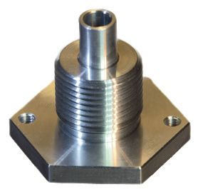
Explosion protection (option)

The permissible power, Pmax, as well as the permissible
ambient temperature, for the respective category can be
seen on the certificate for hazardous areas or in the operating
instructions.

Transmitters have own certificates for hazardous areas.
The permissible ambient temperature ranges of the built-in
transmitters can be taken from the corresponding transmitter
operating instructions and approvals.

Approvals (explosion protection, further approvals)

 Logo       Description                                                                       Country
            EU declaration of conformity                                                      European Union
            ■ EMC directive 1)
               EN 61326 emission (group 1, class B) and immunity (industrial application)
            ■ RoHS directive
            ■ ATEX directive (option)
               Hazardous areas
               - Ex d  Zone 1 gas                         II 2G Ex db IIB + H2 T6 … T4 Gb
                       Zone 1 gas                         II 2G Ex db IIC T6 ... T4 Gb 2)
                       Zone 21 dust                       II 2D Ex tb IIIC T85 °C Db IP66
            IECEx (option) - in conjunction with ATEX                                         International
            Hazardous areas
            - Ex d  Zone 1 gas                        Ex db IIB + H2 T6 … T4 Gb
                    Zone 1 gas                        Ex db IIC T6 … T4 Gb 2)
                    Zone 21 dust                      Ex tb IIIC T85 °C Db IP66
            EAC (option)                                                                      Eurasian Economic
            Hazardous areas                                                                   Community
            - Ex d  Zone 1 gas                            1Ex d IIC T6 ... T4 Gb X
                    Zone 1 gas                            1Ex d IIB+H2 T6 ... T4 Gb X
                    Zone 21 dust                          Ex tb IIIC T85°C Db X
            Ex Ukraine (option)                                                               Ukraine
            Hazardous areas
            - Ex d  Zone 1 gas                            II 2G Ex db IIB+H2 T6 ... T4 Gb
                    Zone 1 gas                            II 2G Ex db IIC T6 ... T4 Gb
                    Zone 1 mounting to zone 0 gas         II 1/2G Ex db IIC T6 ... T4 Ga/Gb
                    Zone 21 dust                          II 2D Ex tb IIIC T85°C Db
            INMETRO (option)                                                                  Brazil
            Hazardous areas
            - Ex d  Zone 1 gas                            Ex db IIB + H2 T6 … T4 Gb IP66
                    Zone 1 gas                            Ex db IIC T6 … T4 Gb IP66
            CCC (option) 3)                                                                   China
            Hazardous areas
            - Ex d Zone 1 gas                             Ex d IIB+H2 T4~T6 Gb
                   Zone 1 gas                             Ex d IIC T4~T6 Gb
                   Zone 21 dust                           Ex tD A21 IP66 T85°C
            GOST (option)                                                                     Russia
            Metrology, measurement technology
            KazInMetr (option)                                                                Kazakhstan
            Metrology, measurement technology
 -          MTSCHS (option)                                                                   Kazakhstan
            Permission for commissioning
            BelGIM (option)                                                                   Belarus
            Metrology, measurement technology

WIKA data sheet TE 60.12 ∙ 03/2021                                                                       Page 2 of 14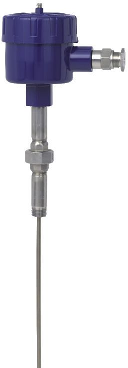
Logo             Description                                                                      Country
                  UkrSEPRO                                                                         Ukraine
                  Metrology, measurement technology
                  Uzstandard                                                                       Uzbekistan
                  Metrology, measurement technology

1) Only for built-in transmitter
2) With suitable solid-machined thermowell
3) Without transmitter

Manufacturer’s information and certificates

 Logo             Description
                  SIL 2
                  Functional safety (only in conjunction with model T32 temperature transmitter)

Approvals and certificates, see website

 WIKA data sheet TE 60.12 ∙ 03/2021                                                                             Page 3 of 14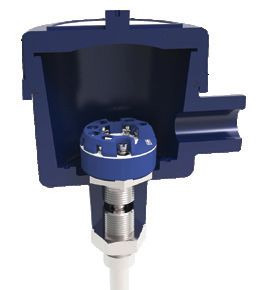
Sensor
Measuring element
Pt100, Pt1000 1) (measuring current: 0.1 ... 1.0 mA) 2)
 Connection method
 Single elements                                  1 x 2-wire
                                                  1 x 3-wire
                                                  1 x 4-wire
 Dual elements                                    2 x 2-wire
                                                  2 x 3-wire
                                                  2 x 4-wire 3)

 Validity limits of class accuracy per EN 60751
 Class                                            Sensor construction
                                                  Wire-wound                                   Thin-film
 Class B                                          -196 ... +600 °C                             -50 ... +500 °C
                                                  -196 ... +450 °C                             -50 ... +250 °C
 Class A 4)                                       -100 ... +450 °C                             -30 ... +300 °C
 Class AA 4)                                      -50 ... +250 °C                              0 ... 150 °C

1) Pt1000 only available as a thin-film measuring resistor
2) For detailed specifications for Pt100 sensors, see Technical information IN 00.17 at www.wika.com.
3) Not with 3 mm diameter
4) Not with 2-wire connection method

The table shows the temperature ranges listed in the
respective standards, in which the tolerance values (class
accuracies) are valid.

Electrical connection (colour code per IEC/EN 60751)

                   1 x Pt100, 2-wire                                            1 x Pt100, 3-wire                    1 x Pt100, 4-wire

                                                                                                        red         white               red

                                                                                                                                                       3160629.06
               white                        red                              white                      red         white               red

                                                                                                        red                             red
                                           red                                                          red                             red
                                           white                                                        white                           white
                                                                                                                                        white

                  2 x Pt100, 2-wire                                              2 x Pt100, 3-wire                       2 x Pt100, 4-wire
                                                                       black
                                                                                                                 black                 yellow
           black                           yellow                                                       yellow

               white                        red                              white                                 white                red
                                                                                                         red

                                                                                                        red                             red
                                           red                                                          red                             red
                                           white                                                        white                           white
                                                                                                                                        white
                                           black                                                        black                           black
                                                                                                        black                           black
                                           yellow                                                       yellow                          yellow
                                                                                                                                        yellow

For the electrical connections of built-in temperature transmitters see the corresponding data sheets or operating instructions.

 WIKA data sheet TE 60.12 ∙ 03/2021                                                                                                           Page 4 of 14
Connection head
NuG)1/40001/4000 1/4000
1/4000 F5/6000
5/6000 7/8000 W
7/80007/8000
5/6000 7/8000
7/8000
7/8000 WDIH50
7/8000
DIH50 / DIH50
7/8000 DIH50
andereandere
Anschlussgehäuse
Anschlussgehäuse KN4-PKN4-P
andere Anschlussgehäuse KN4-P
BVC BVC BVC
1/4000 S 7/8000 S 7/8000 S / DIH50
Model Material Cable entry thread size Ingress protection Cover / Surface Connection
(max.) 1) Cap to neck tube
IEC/EN 60529
1/4000 F Aluminium ½ NPT, ¾ NPT, M20 x 1.5 IP66 2) Screw-on lid Blue, lacquered 3) ½ NPT
1/4000 S Stainless steel ½ NPT, ¾ NPT, M20 x 1.5 IP66 2) Screw-on lid Blank ½ NPT
7/8000 W Aluminium ½ NPT, ¾ NPT, M20 x 1.5 IP66 2) Screw-on lid Blue, lacquered 3) ½ NPT
7/8000 S Stainless steel ½ NPT, ¾ NPT, M20 x 1.5 IP66 2) Screw-on lid Blank ½ NPT
7/8000 W / Aluminium ½ NPT, ¾ NPT, M20 x 1.5 IP66 2) Screw-on lid Blue, lacquered 3) ½ NPT
DIH50 4)
7/8000 S / Stainless steel ½ NPT, ¾ NPT, M20 x 1.5 IP66 2) Screw-on lid Blank ½ NPT
DIH50 4)
1) IP ingress protection of the connection head. The IP ingress protections of the complete instrument TR10-L must not inevitably correspond to the connection head.
2) Ingress protections, which describe temporary or lasting submersion, available on request
3) RAL 5022
4) LC display DIH50
Connection head with digital display Flame path fitting
A flame path fitting is built into the connection head which, in
conjunction with the measuring insert, generates a flame-
proof gap.
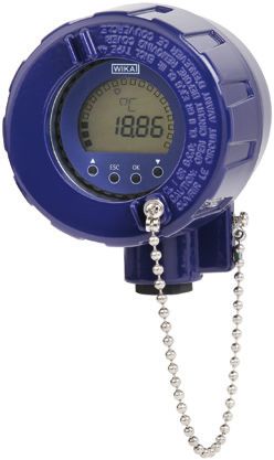
Connection head 7/8000 W with LC display, model DIH50
see data sheet AC 80.10
Fig. left: Flame path fitting for model 1/4000
connection head
To operate the digital display, a transmitter with a 4 ... 20 mA Fig. right: Flame path fitting for 7/8000 and 7/8000
output is always required. connection heads with DIH50
WIKA data sheet TE 60.12 ∙ 03/2021 Page 5 of 14Cable entry
Ex d cable gland Plain threaded Sealing plugs for
stainless steel transport
The pictures show examples of threaded connections and connection heads.
Cable entry Cable entry thread size Min./max. ambient temperature
Ex d cable gland stainless steel M20 x 1.5 or ½ NPT -60 1) / -40 ... +80 °C
Plain threaded M20 x 1.5 or ½ NPT -
Sealing plugs for transport M20 x 1.5 or ½ NPT -40 ... +80 °C
Cable entry Colour Ingress protection (max.) 2)
IEC/EN 60529
Ex d cable gland stainless steel Blank IP66
Plain threaded - IP00
Sealing plugs for transport Transparent -
1) Special version on request (only available with selected approvals), other temperatures on request
2) IP ingress protection of the connection head. The IP ingress protections of the complete instrument TR10-L must not inevitably correspond to the connection head.
WIKA data sheet TE 60.12 ∙ 03/2021 Page 6 of 14Ingress protection per IEC/EN 60529
Degrees of protection against solid foreign bodies (defined by the first index number)
First index number Degree of protection / short description Test parameter
5 Dust-protected per IEC/EN 60529
6 Dust-tight per IEC/EN 60529
Degrees of protection against water (defined by the second index number)
Second index number Degree of protection / short description Test parameter
4 Protected against splash water per IEC/EN 60529
5 Protected against water jets per IEC/EN 60529
6 Protected against strong water jets per IEC/EN 60529
7 1) Protected against the effects of temporary immersion in water per IEC/EN 60529
8 1) Protected against the effects of continuous immersion in water by agreement
1) Ingress protections, describing temporary or permanent immersion, on request
Standard ingress protection of model TR10-L is IP65.
The stated degrees of protection apply under the following
conditions:
■ Use of a suitable thermowell
(without suitable thermowell: IP40)
■ Use of a suitable cable gland
■ Use of a cable cross-section appropriate for the gland or
select the appropriate cable gland for the available cable
■ Adhere to the tightening torques for all threaded
connections
Transmitter
Mounting onto the measuring insert
With mounting on the measuring insert, the transmitter
replaces the terminal block and is fixed directly to the
terminal plate of the measuring insert.
Fig. left: Measuring insert with mounted transmitter (here: model T32)
Fig. right: Measuring insert prepared for transmitter mounting
WIKA data sheet TE 60.12 ∙ 03/2021 Page 7 of 14Transmitter models
Output signal 4 ... 20 mA, HART® protocol
Transmitter (selectable versions) Model T15 Model T32
Data sheet TE 15.01 TE 32.04
Output
4 ... 20 mA x x
HART® protocol - x
Connection method
1 x 2-wire, 3-wire or 4-wire x x
Measuring current < 0.2 mA < 0.3 mA
Explosion protection Optional Optional
Possible mounting positions for transmitters
Connection head T15 T32
1/4000 F, 1/4000 S ○ ○
7/8000 W, 7/8000 S ○ ○
7/8000 W / DIH50, 7/8000 S / DIH50 ○ ○
○ Mounted instead of terminal block – Mounting not possible
The mounting of a transmitter on the measuring insert is possible with all the connection heads listed here. The fitting of a
transmitter in the (screw) cap of a North American design connection head is not possible.
Mounting of 2 transmitters on request.
For a correct determination of the overall measuring deviation, the sensor and transmitter measuring deviations must be added.
Functional safety (option)
with temperature transmitter model T32
In safety-critical applications, the entire measuring chain
must be taken into consideration in terms of the safety
parameters. The SIL classification allows the assessment of
the risk reduction achieved by the safety installations.
Selected TR10-L resistance thermometers, in combination
with a suitable temperature transmitter (e.g. model T32.1S,
TÜV certified SIL version for protection systems developed
in accordance with IEC 61508), are suitable as sensors for
safety functions to SIL 2.
For detailed specifications, see Technical information
IN 00.19 at www.wika.com.
WIKA data sheet TE 60.12 ∙ 03/2021 Page 8 of 14Components model TR10-L
“Nipple-union-nipple” neck tube
3112147.04
Double threaded hex bushing (tube section)
Double threaded hex bushing (with hexagonal spanner flats)
3112287.03
Legend:
Neck tube with counter nut to head Connection head
Neck tube
Connection to thermowell
Measuring insert
Transmitter (option)
Flame path fitting
A (l1) Insertion length
(with parallel threads)
A (U2) Insertion length
(with tapered threads)
l5 Measuring insert length
Ød Measuring insert diameter
NL Nominal length
N (MH) Neck length
WIKA data sheet TE 60.12 ∙ 03/2021 Page 9 of 14Neck tube
Neck tube designs
“Nipple-union-nipple” neck tube Double threaded hex bushing (tube section)
14235871.01
3116003.01
Thread Thread
Double threaded hex bushing Neck tube with counter nut to head
(with hexagonal spanner flats)
14235871.01
3115995.01
Thread Thread
Legend:
A (l1) Insertion length (with parallel threads) Ød Measuring insert diameter
A (U2) Insertion length (with tapered threads) KE Screw-in length by hand
N (MH) Neck length - with ½ NPT approx. 8.1 mm
- with ¾ NPT approx. 8.6 mm
WIKA data sheet TE 60.12 ∙ 03/2021 Page 10 of 14Neck tube versions
Neck tube design Diameter Connection to head Connection to thermowell Material
“Nipple-union-nipple” neck tube ~ 22 mm ½ NPT Mounting thread 316
(nipple-union-nipple) ~ 27 mm ¾ NPT
Double threaded hex bushing ~ 22 mm ½ NPT Mounting thread 316
(tube section) ~ 27 mm ¾ NPT
Double threaded hex bushing - M24 x 1.5, ½ NPT Mounting thread 1.4571
(with hexagonal spanner flats)
Neck tube with counter nut to head 14 x 2.5 mm M20 x 1.5 (with counter nut) Mounting thread 1.4571
Thread sizes
Neck tube design Diameter Thread to the thermowell
“Nipple-union-nipple” neck tube ~ 22 mm ½ NPT
~ 27 mm ¾ NPT
Double threaded hex bushing (tube section) ~ 22 mm ½ NPT
~ 27 mm ¾ NPT
Double threaded hex bushing (with hexagonal - G½B
spanner flats) G¾B
G¼B
½ NPT
¾ NPT
M14 x 1.5
M18 x 1.5
M20 x 1.5
Neck tube with counter nut to head 14 x 2.5 mm ½ NPT
¾ NPT
G½B
G¾B
G¼B
M14 x 1.5
M18 x 1.5
M20 x 1.5
Neck lengths
Neck tube design Neck length Min. / Max. neck length
“Nipple-union-nipple” neck tube 150 mm [approx. 6 in] 75 mm [approx. 3 in] / 250 mm [approx. 10 in]
Double threaded hex bushing (tube section) 50 mm [approx. 2 in] 50 mm [approx. 2 in] / 250 mm [approx. 10 in]
Double threaded hex bushing (with hexagonal 25 mm
spanner flats)
Neck tube with counter nut to head 150 mm [approx. 6 in] 75 mm [approx. 3 in] / 250 mm [approx. 10 in]
The neck tube is screwed into the connection head. The neck length depends on the intended use. Usually an isolation is
bridged by the neck tube. Also, in many cases, the neck tube serves as a cooling extension between the connection head and
the medium, in order to protect a possible built-in transmitter from high medium temperatures.
Other versions on request
WIKA data sheet TE 60.12 ∙ 03/2021 Page 11 of 14Measuring insert
Within the TR10-L, the measuring insert of model TR10-K is Attention:
fitted. Only correct measuring insert length and correct measuring
The replaceable measuring insert is made of a insert diameter ensure sufficient heat transfer from
vibration-resistant, sheathed measuring cable (MI cable). thermowell to the measuring insert. The bore diameter of the
thermowell should be a max. 1 mm larger than the measuring
insert diameter. Gaps of more than 0.5 mm between
thermowell and the measuring insert will have a negative
effect on the heat transfer, and they will result in unfavourable
response behaviour of the thermometer.
When fitting the measuring insert into a thermowell, it is
very important to determine the correct insertion length
(= thermowell length for bottom thicknesses of ≤ 5.5 mm).
Pay special attention to the assembly/disassembly of the In order to ensure that the measuring insert is firmly pressed
measuring insert. The surface of the sheathed cable of down onto the bottom of the thermowell, the measuring insert
the measuring insert must not be damaged! (No creases, must be spring-loaded (spring travel: max. 10 mm).
grooves, scratches etc.). Any damaged measuring insert
must be replaced. It is advisable to renew the corresponding
flame path fitting in this case.
Dimensions in mm
Design prepared for Design with mounted
transmitter mounting transmitter
Spring-loaded screw
Connection terminal
Insulation washer
Terminal plate
Measuring insert
with sleeve in the
11449307.03
sensor area
Legend:
A (l5) Measuring insert length
Ø d Measuring insert diameter
* Ø 45 mm diameter with 2 x Pt100 in 4-wire connection
Measuring insert diameter Ø d in mm Sheath material
3 1) 1.4571, 316L 1)
6 1.4571, 316L 1)
8 (6 mm with sleeve) 1.4571
1) Not possible with 2 x 4-wire versions
WIKA data sheet TE 60.12 ∙ 03/2021 Page 12 of 14Thermowell selection
TW10 TW15 TW20 TW25 TW30
Data sheets: Data sheet: Data sheet: Data sheet: Data sheet:
TW 95.10 TW 95.15 TW 95.20 TW 95.25 TW 95.30
TW 95.11
TW 95.12
TW50 TW55
Data sheet: Data sheet:
TW 95.50 TW 95.55
Special thermowells on request
WIKA data sheet TE 60.12 ∙ 03/2021 Page 13 of 14Operating conditions Certificates (option)
Mechanical requirements Certification type Measurement Material
accuracy certificate 2)
Version 2.2 test report x x
Standard 6 g peak-to-peak, wire-wound measuring resistor or 3.1 inspection certificate x x
thin film
DKD/DAkkS calibration x -
Option Vibration-resistant probe tip, max. 20 g peak-to-peak, certificate
thin-film measuring resistor
Highly vibration-resistant probe tip, 2) Thermowells have their own material certificates
max. 50 g peak-to-peak, thin-film measuring resistor
The different certifications can be combined with each other.
The information on vibration resistance refers to the tip of the
measuring insert. For calibration, the measuring insert is removed from
the thermometer. The minimum length (metal part of the
For detailed specifications on the vibration resistance probe) for carrying out a measurement accuracy test 3.1 or
of Pt100 sensors, see Technical information IN 00.17 at DKD/DAkkS is 100 mm.
www.wika.com. Calibration of shorter lengths on request.
Ambient and storage temperature
-60 1) / -20 ... +80 °C
1) Special version on request
Other ambient and storage temperatures on request
Ordering information
Model / Explosion protection / Process connection / Version and material of threaded connection / Thread size / Measuring
element / Connection method / Temperature range / Probe diameter / Insertion length A / Neck length N(MH) / Certificates /
Options
© 09/2003 WIKA Alexander Wiegand SE & Co. KG, all rights reserved.
The specifications given in this document represent the state of engineering at the time of publishing.
We reserve the right to make modifications to the specifications and materials.
WIKA data sheet TE 60.12 ∙ 03/2021 Page 14 of 14
03/2021 EN
WIKA Alexander Wiegand SE & Co. KG
Alexander-Wiegand-Straße 30
63911 Klingenberg/Germany
Tel. +49 9372 132-0
Fax +49 9372 132-406
info@wika.de
www.wika.deYou can also read