Fault detection and diagnosis of historical vehicle engines using acoustic emission techniques - Acta IMEKO
←
→
Page content transcription
If your browser does not render page correctly, please read the page content below
ACTA IMEKO
ISSN: 2221-870X
March 2021, Volume 10, Number 1, 77 - 83

Fault detection and diagnosis of historical vehicle engines
using acoustic emission techniques
Alejandro Roda-Buch1,2, Emilie Cornet1, Guillaume Rapp1, Brice Chalançon3, Stefano Mischler2, Laura
Brambilla1
1 Haute Ecole Arc Conservation-Restauration, HES-SO University of Applied Sciences and arts Western Switzerland, Espace de l’Europe 11,
 CH-2000, Neuchâtel, Switzerland
2 Ecole Polytechnique Fédérale de Lausanne, EPFL CH-1015, Lausanne, Switzerland
3 Association de Gestion du Musée National de l’Automobile, 188 Av. de Colmar, 68100 Mulhouse, France

 ABSTRACT
 The reactivation of artefact mechanisms is always a challenge for conservators. Non-invasive diagnostic techniques, applicable directly
 on the artifacts, allows for performing early-stage diagnostics and avoiding damage. The Acoustic Emission Monitoring of Historical
 Vehicles (ACUME_HV) project represents the first use of acoustic emission (AE) as a non-invasive technique for the diagnostics of
 historical vehicles. The aim of this project is to develop an objective, human-independent method. This will help museum personnel to
 make decisions regarding the reactivation of historical vehicle engines using measurements and data analysis rather than merely
 personal experience. Herein, we present the results of the first phase of the ACUME_HV project, which was focused on the development
 of a protocol for the use of AE during cold tests.

Section: RESEARCH PAPER
Keywords: Historical vehicles; acoustic emission; NDT; fault diagnosis
Citation: Alejandro Roda-Buch, Emilie Cornet, Guillaume Rapp, Brice Chalançon, Stefano Mischler, Laura Brambilla, Fault detection and diagnosis of historical
vehicle engines using acoustic emission techniques, Acta IMEKO, vol. 10, no. 1, article 11, March 2021, identifier: IMEKO-ACTA-10 (2021)-01-11
Editor: Eulalia Balestrieri, University of Sannio, Italy
Received May 1, 2020; In final form September 26, 2020; Published March 2021
Copyright: This is an open-access article distributed under the terms of the Creative Commons Attribution 3.0 License, which permits unrestricted use,
distribution, and reproduction in any medium, provided the original author and source are credited.
Funding: This work was supported by HES-SO RCDAV funding, Switzerland
Corresponding author: Laura Brambilla, e-mail: laura.brambilla@he-arc.ch

 systems involved in their functioning. Given the aforementioned
1. INTRODUCTION obstacles to the reactivation of historical engines, the choice of
 exhibition and maintenance of the vehicles in museums and
 The peculiarity of the objects constituting technical, collections is generally reduced to the following two options:
industrial, and scientific cultural heritage lies in the presence of i. static: the vehicle is exposed and its engine is never
specific mechanisms. The functionality of these artefacts, i.e. the operated (on occasion, the engine is even removed
possibility of making them work, is an integral part of the objects from the vehicle for practical and safety reasons);
themselves. The reactivation of these mechanisms, however, is ii. dynamic: the vehicle is used, or at least activated
often a challenge for the conservators, especially if the periodically.
functioning has been stopped for a long period of time. In short, In order to be able to reactivate the mechanisms without
the presence of corrosive products, deposits, oxidation, and damage while simultaneously preserving the cultural value and
particles, as well as the scaling of oils or lubricants, can prevent the original materials of the objects, the conservators require
the mechanisms from working properly or can even lead to their specific diagnostic tools for the detection of any malfunctions at
breakdown during reactivation. In addition, the reactivation a very early stage.
procedure must be performed while respecting the material In the field of historical vehicle conservation, there currently
authenticity of the object, i.e. preserving the original parts of the exists no reliable non-invasive technique for the diagnosis and
mechanism as far as possible. monitoring of the engine’s functioning. Therefore, the
 Among the objects that incorporate mechanisms, vehicles are maintenance of old engines is extremely time consuming and
especially complex due to of the number of parts and or sub-

ACTA IMEKO | www.imeko.org March 2021 | Volume 10 | Number 1 | 77
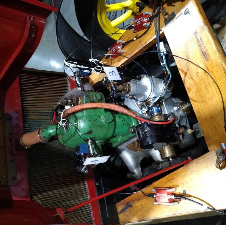
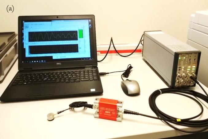
requires personnel with specialised competency. Indeed, the discussed methodology. In section 4, the results accounting for
assessment of the correct functioning is generally left to the the non-uniform driving speed of the engine during the tests are
expertise of the specialists, who tend to largely base their presented and discussed as is a comparison between the tests to
evaluation on previous experience, using methods ranging from discriminate the effect of compression in the cylinders. Finally,
visual examination to listening to the sound of the engine. the main conclusions are summarised in section 5.
However, this approach is empirical, human-dependent, and has
never been correctly standardised. 2. METHODOLOGY
 As such, the use of non-invasive techniques, such as acoustic
emission (AE) techniques [1], for the evaluation of the A reliable diagnostic tool must have the capacity to capture
mechanisms’ condition could prevent damage occurring during signal features that can be correlated with the state of the system.
the reactivation and could help in developing a monitoring The conservation/restoration procedure for reactivating an
protocol based on factual measurements. engine [27] begins with a visual inspection of the whole engine
 The Acoustic Emission Monitoring of Historical Vehicles in view of evaluating the general condition of the individual
(ACUME_HV) project, led by HE-Arc CR, represents the first components. At this stage, the liquids of the oil and cooling
use of AE as a non-invasive technique for the diagnostics of systems are changed and the accessorial components are repaired
historical vehicles, and was carried out in collaboration with the where necessary. Prior to starting the engine, the next step
Musée National de l’Automobile de Mulhouse (MNAM) in involves assessing the functioning of the mechanisms. In order
France. The aim of this project is to develop an objective, to achieve this, the engine is moved manually before an expert
human-independent method that will assist museum personnel checks the engine’s operation, both visually and acoustically. This
with their decision making regarding the reactivation of historical procedure is known as a ‘cold test’ and is performed without
vehicle engines using measurements and data analysis rather than starting the engine to minimise the possible damage during the
personal experience alone. reactivation process. To ensure this condition, the combustion
 The use of the AE technique has already been applied to the process is excluded from the evaluation, with only the
diagnosis of faults during the operation of newly produced mechanical displacements taken into account [27].
engines [2]-[10]. Here, El-Ghambry et al. [4] analysed the AE rms At this critical stage, the procedure developed during the
signals of diesel engines in the time domain in view of identifying ACUME_HV project will be introduced in view of replacing the
– using the machine timing – machine fault conditions. The human-dependent diagnosis, with the measurement of the AE
authors used selective time windowing of the AE signals and signals generated by friction and/or impacts at different contact
different statistical features and pattern recognition techniques to pairs of the engine mechanisms, such as crankshaft/connecting
isolate and identify various fault conditions in reciprocating rod, connecting rod/piston, piston rings/cylinder liner, as well
engines. as inside the cam chain system. The airflow or air leakage at the
 Meanwhile, Douglas et al. [5] studied the interaction between valve inlets/outlets and between the piston-ring/cylinder-liner
piston rings and cylinder liners using AE for in-service engine gaps can also be detected at this point. The following step of this
monitoring and found that, for small high-speed direct injection new procedure involves obtaining the mechanical signature of
(HSDI) engines, the AE activity was proportional to the piston the engine for different reactivating conditions (i.e. with/without
speed and that the most likely AE source (among other cylinder compression). Finally, the last step involves the use of
contributions) was the boundary friction between the oil-control statistical analysis techniques to extract specific features that will
ring and the cylinder liner. then be used to classify and correlate the operational state of the
 Various analytical models and predictive tools [11]-[19] have mechanical parts of the engine.
been developed through using the AE technique to characterise First, the method was tested on an engine that was removed
and model the friction and wear in sliding contacts under various from the vehicle to ensure complete access to all the parts of the
lubricated conditions, including the scuffing phenomenon. engine. This engine, known as a ‘bench engine’, was bought by
 Meanwhile, in the field of cultural heritage, the AE technique the MNAM as a spare for the possible reparation of certain
has been used for monitoring the conservation state of heritage vehicles in their collection. The engine was mounted on a test
objects or for detecting insects in wooden musical instruments bench while keeping all of the cam system and pump
[20]-[22]. In addition, AE has been used for several years for the mechanisms operative. The mechanical parts were manually
structural damage analysis and health monitoring of historical operated at a relatively low rotating speed through turning the
masonry buildings. Of particular interest in this domain is the crankshaft via a handle. This procedure allowed for maintaining
application of the Gutenberg–Richter (GBR) law to AE good control of the interplay between different parts, thus
measurements in order to correlate the magnitude and the avoiding possible damage to the machine.
number of events within a certain time period [23]-[26].
 Despite the extended use of the AE technique in the field of 3. ENGINE, MEASUREMENT SYSTEM AND TEST SETS
modern engine diagnosis, the capacity of this technique for The AE tests were performed on two Renault AG1-type
providing valuable diagnostic results remains a challenge in the engines (Figure 1), which are part of the collection held by the
field of cultural heritage. In short, the attendant limitations arise Musée National de l’Automobile de Mulhouse. Among the
from the technical characteristics of the historical vehicles and reasons for selecting this specific model were the easy access to
their conservation state, mainly in the case of reactivation most parts of the engine, even when assembled in the vehicle,
processes. the simplicity of the engine, which has only two cylinders and
 The present work is organised in terms of five sections. In basic auxiliary systems, and the availability at MNAN of three
section 2, the methodology adopted for the ACUME_HV identical engines (AG1), two of which are still in working order
project to define a protocol for the reactivation of the historical [28].
vehicle engines is described before section 3 describes the The measurement equipment is shown in Figure 2a, while a
measuring system and the set of tests carried out to follow the block diagram of the experimental set-up is schematised in

ACTA IMEKO | www.imeko.org March 2021 | Volume 10 | Number 1 | 78
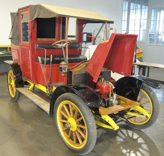
Figure 2b. An AE system from Vallen® was used to acquire the
AE signals, which included a MB2-V1 chassis with four AE
sensors and four parametric input channels. The four broadband
AE sensors were VS900-M (between 100 and 900 kHz) sensors,
with the corresponding AEP5 preamplifiers (+34 dB) also
included in the system. The sampling frequency of the AE signals
was set to 2 MHz, while a 1-MHz low pass filter was used to
reduce the noise from high frequencies. The crankshaft angular
position was also measured with a full continuous 360 ° smart
position sensor (VISHAY Spectrol 601-1045; output signal 0–
5 V) at a sampling rate of 1.25 kHz.
 To carry out this research, three different sets of tests were
implemented. An initial set of measurements was performed to
determine the optimal location of the AE sensors for obtaining
representative signals from different AE sources [29], [30]. The
locations selected for the following sets of tests were those
 DAQ +
presenting higher signal levels, lower signal-to-noise ratios, and
 conditioning
the highest presence of events for the measured AE signals.
Figure 3 shows the final locations of the four AE sensors. Here,
two were placed on the cylinder block, the first (1) on the outer
part of the first cylinder (the one closest to the front), and the
second (2) on the opposite side close to the first cylinder valves. Acoustic
 emission
Meanwhile, the remaining two sensors were placed on the sensor
crankcase, one (3) on the cover of the gears of the cam system, PC + Signal
and the other (4) on the crankcase leg of the valve side. (b)
 Tested Analysis Techniques
 A second set of tests was then conducted to analyse the effect engine
of the engine speed on the AE signal level. In this set, the spark
plugs of both cylinders were removed to prevent air compression
inside the cylinders and, consequently, to produce a smoother Figure 2. (a) Vallen® measurement system of AE signals, (b) block diagram of
 the experimental set-up (© HE-Arc CR, 2018).
and more constant motion of the engine. Here, different engine
speeds were tested, ranging from 0.25 to 1.2 cycles per second
(cps), with the engine activated manually using an external Test sets 2 and 3 were also performed on two different
handle. engines to observe the main characteristics of the mechanical
 Finally, a third set of tests was performed to observe the signature and the mechanical airflow signature of different
influence of the compression of the air inside the cylinders on motors of the same type, that is, the bench engine already used
the AE signals. The results obtained with the spark plugs for test set 1 and the engine of the collection car, which remained
removed (set 2) were then compared with those obtained with mounted in the car.
the plugs left in (set 3).

Figure 1. Renault AG1 (Inv.2209) with its 2 cylinder engine (© MNAM, 2016). Figure 3. AE sensor location on the Renault AG1 engine (© HE-Arc CR, 2019).

ACTA IMEKO | www.imeko.org March 2021 | Volume 10 | Number 1 | 79
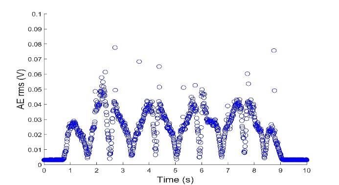
the piston passed by the TDC before the crankshaft was rotated
 by four revolutions and its movement was extended for a little
 longer. This procedure guaranteed that two thermodynamic
 cycles were fully recorded. Figure 4c was obtained using the time
 derivative of the curve in Figure 4b.
 It was clear that there was a high correlation between the AE
 rms feature and the crankshaft angular position and,
 consequently, the relative motion of the piston to the cylinder.
 Minimum AE rms values emerged at the TDC and the bottom
 dead centre (BDC) of both pistons where the piston speed was
 (a) the lowest, while maximum values emerged at the mid position
 between the TDC and BDC where the piston speed was
 maximised. This indicates that the main source of the AE waves
 was the sliding friction between the piston rings and the cylinder
 liners. Another outcome that must be highlighted is that the
 crankshaft rotational speed was not constant throughout the test
 (Figure 4c), which was due to the way the motion was driven (i.e.
 manually) and to the variable resistance torque of the engine
 during its motion.
 A normalisation of the AE rms feature to a defined crankshaft
 rotational speed of 0.5 cps was performed in order to compare
 the AE rms feature for different crankshaft positions obtained at
 different speeds with both the same test and with different tests.
 (b) This speed was selected since it can be easily reached in cold tests
 both with and without air compression inside the cylinders. To
 transform the AE rms from the measured signal to the
 normalised speed, a proportional relationship described by Eq. 1
 was applied at regular time intervals of 10 ms:
 0.5
 , ( ) = , ( ) (1)
 ( )
 where AErms,norm(t) and AErms,meas(t) are the AE features normalised
 and measured, respectively, and nmeas(t) and 0.5 are the measured
 crankshaft rotational speed (in cps) and the normalised speed for
 the corresponding time interval, respectively. This
 (c) transformation is based on the results obtained by Douglas et al.
 [5], which indicated that the AE energy generated during the
Figure 4. Time evolution of (a) AE rms signal of sensor 1, (b) crankshaft
angular position, (c) crankshaft rotational speed.
 sliding friction between the piston rings and the cylinder liners is
 proportional to the relative speed between the solids in contact.
 This result was confirmed, for the range of speeds tested, by
 observing the AE rms from measured signals as a function of the
4. RESULTS speed at different crankshaft positions (see Figure 5).
 In this section, the results for two specific studies are
presented. The first study relates to the influence of the rotational
speed of the engine on the AE feature and the second to the
mechanical signature and the mechanical airflow signature of the
two engines.
 The root means square of the AE signals (AE rms) was the
feature used to extract the mechanical and air compression
signature of the engine under cold-test conditions. The rms was
calculated for blocks of signals with a rate of 10 ms. This feature
is related to the AE signal energy generated by, for example, the
sliding friction processes in contact pairs [6].
4.1. Engine speed influence in acoustic emission signal feature
 Figure 4a shows the time change of the AE rms of the
cylinder at sensor 1, Figure 4b the angular position, and Figure
4c the rotational speed of the crankshaft. In Figure 4b, the
crankshaft angular position is related to the thermodynamic cycle
of the engine, which is comprised of 720 ° or two complete
crankshaft revolutions. When the first piston was at the top dead
centre (TDC) position, the rotation reached angular values of 0 Figure 5. AE rms signal of sensor 3 vs. crankshaft rotational speed at ±75 °
°, 360 ° or 720 °. It can be seen that the test started slightly before from TDC.

ACTA IMEKO | www.imeko.org March 2021 | Volume 10 | Number 1 | 80
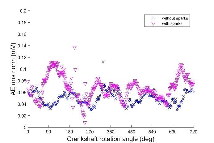
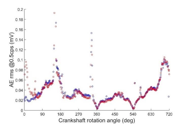
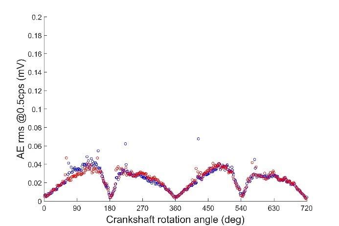
(a) (b)
Figure 6. Normalised AE rms signals of sensor 1 with spark plugs removed: (a) bench engine, (b) collection engine.

 cylinders, are plotted in Figure 7 for the two previously tested
4.2. Acoustic emission signatures
 engines.
 The normalised AE rms signals measured using cylinder Two main differences can be observed for the results with
sensor 1 in relation to the crankshaft angular position are plotted (Figure 7) and without (Figure 6) spark plugs. First, there was a
in Figure 6 for the two different engines: (a) the bench engine clear increase in AE rms level in the range of 90 °–180 ° and 630
and (b) the collection car engine. °–720 °, which was associated with the compression phase of the
 The crankshaft rotation evolved for two complete second and first cylinder, respectively. Second, various punctual
thermodynamic cycles (0 °–720 °; first cycle in blue and second spiky AE events that were related to the valves’ opening and
cycle in red) corresponding to four full revolutions of the closing operations emerged. The AE rms signals shown in Figure
crankshaft. The TDC of cylinders 1 and 2 corresponded to a 0 ° 7 are the combination of the mechanical signature (Figure 6) and
and a 180 ° rotation, respectively. Both pistons completed four the AE events from the airflows in the compression phases and
back-and-forth reciprocating motions, while every pass through the valve operation of the engine when the spark plugs were left
the TDC and the BDC corresponded to a change in speed in.
direction, where the piston speed was null. At these points, the A deeper analysis of the data shown in Figure 7 allowed for
AE rms was close to zero, which confirmed that the main source the detection of a failure in the valve system of the collection
of the AE events in the cylinder block was the sliding friction engine (case b). The AE rms signals of the bench engine (Figure
between the piston rings and the cylinder liner. The absence of 7a) during the compression phases of both cylinders (90 °–180 °
air compression inside the cylinders prevented, in these cases, the and 630 °–720 ° for the second and first cylinders, respectively)
generation of AE waves from airflows. presented a similar evolution. On the contrary, for the collection
 The results are clearly reproducible for every engine when the engine (Figure 7b), the signal evolution of the compression phase
normalised AE rms is taken into account. These results represent of the second cylinder (90 °–180 °) was significantly different (in
the mechanical signature (with an absence of air compression) of both shape and level) from the signal of the compression phase
the engine’s condition. In fact, when comparing the AE rms of the first cylinder (630 °–720 °). After noting this divergent
evolution between the two engines, it became clear that the compression evolution, a specific test was performed to check
mechanical signature is univocally representative of the engine. the airtightness of the second cylinder, which revealed a fault in
 The normalised AE rms signals of sensor 1 when the spark the seat of the intake valve, leading to a loss in compression of
plugs were left in, meaning air was compressed inside the around 35 %.

(a) (b)
Figure 7. Normalised AE rms signals of sensor 1 with spark plugs left in: (a) bench engine, (b) collection engine.

ACTA IMEKO | www.imeko.org March 2021 | Volume 10 | Number 1 | 81
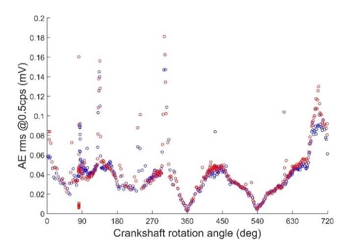
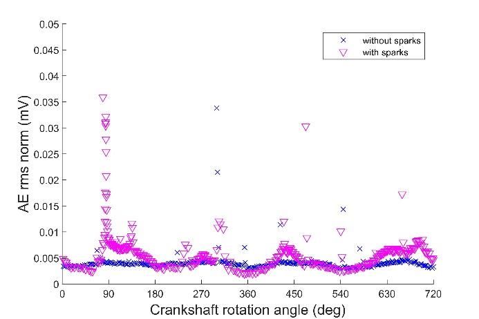
(a) (b)
Figure 8. Normalised AE rms signals of sensor 3: (a) bench engine, (b) collection engine.

 This malfunctioning behaviour could also be observed when reliable signature of the actual working condition of an engine is
analysing the AE rms signals of other channels. Figure 8 shows registered, this diagnostic tool can be used to compare or analyse
the normalised AE rms evolution for the bench (case a) and the evolution of the future engine signatures in relation to the
collection (case b) engines. Here, the results without (in blue) and reference signature. As such, a database of the engines of an
with (in red) spark plugs are superimposed for each engine. On existing collection could be created and stored for future
comparing the red results in both graphs, it was clear that while comparisons.
the signal evolution during the compression phase for the bench
engine was quite similar, the signal of the collection engine
presented a spike at around 90 ° (marked with arrows in Figure ACKNOWLEDGEMENTS
7b) during the compression phase of the second cylinder. This
event was not observed either in the compression phase of the The authors wish to acknowledge HES-SO RCDAV for
first cylinder of the collection engine or in the compression funding the ACUME_HV project, the Musée Nationale de
phases of the bench engine. l’Automobile in Mulhouse (France) for their material and
 technical support, and Jean-Charles Peruchetti, lecturer at
 ENSISA in Mulhouse (France), for the development of the
5. CONCLUSIONS
 engine’s angular speed monitoring sensor.
 In this paper, a diagnostic tool based on AE measurements
was developed to help conservation/restoration specialists in REFERENCES
reactivating historical vehicle engines. This new tool will provide
innovative and more objective diagnostic features that are free of [1] C. B. Scruby, An introduction to acoustic emission, J. Phys. E: Sci.
 Instrum. 20 (1987), pp. 946-953.
human subjective evaluation. By performing cold tests at the DOI: 10.1088/0022-3735/20/8/001
initial reactivation stages to prevent any damage to the heritage [2] S. Delvecchio, P. Bonfiglio, F. Pompoli, Vibro-acoustic condi-
artefacts, the mechanical signature of the engine’s condition can tion monitoring of internal combustion engines: a critical review
be obtained from appropriate AE measurements. of existing techniques, Mech. Syst. and Signal Proc. 99 (2018),
 In order to collect reliable AE signals for various types of pp. 661-683.
engine, a preliminary study should be performed in view of DOI: 10.1016/j.ymssp.2017.06.033
determining the correct sensor positions, which will ensure that [3] B.C. Kaul, B. Lawler, A. Zahdeh, Engine diagnostics using
appropriate signatures for performing an accurate diagnosis of acoustic emissions sensors, SAE Int. J. Engines 9(2) (2016), pp.
the engine’s condition will be obtained. 684-692.
 DOI: 10.4271/2016-01-0639
 When using AE rms features, the influence of the crankshaft [4] M. H. El-Ghambry, R. L. Reuben, J. A. Steel, The development of
rotational speed in the signal levels must be taken into account. automated pattern recognition and statistical feature isolation
In this work, for the range of speeds used in the tests, a techniques for the diagnosis of reciprocating machinery faults
proportional correlation was applied to normalise the AE rms using acoustic emission, Mech. Syst. and Signal Proc. 17(4) (2003),
signal. This normalisation procedure ensured good pp. 805-823.
reproducibility of the obtained signals. The use of a controlled DOI: 10.1006/mssp.2002.1473
speed system for driving the engine motion or the use of other [5] R. M. Douglas, J. A. Steel, R. L. Reuben, A study of the tribo-
analytical techniques in the frequency or time-frequency domains logical behaviour of piston ring/cylinder liner interaction in diesel
 engines using acoustic emission, Tribology International 39
could help to avoid the issue of non-constant rotational speeds.
 (2006), pp. 1634-1642.
 The preliminary results demonstrated that performing cold DOI: 10.1016/j.triboint.2006.01.005
tests using this AE technique is a promising approach to [6] P. Nivesrangsan, J. A. Steel, R. L. Reuben, Source location of
detecting various malfunctions (e.g. air leakages in the valves), acoustic emission in diesel engines, Mechanical Systems and Signal
one that involves applying adequate data treatment procedures Processing 21 (2007), pp. 1103-1114.
to the AE features obtained from the mechanical signatures of DOI: 10.1016/j.ymssp.2005.12.010
the engines. [7] S. Johansson, P. H. Nilsson, R. Ohlsson, B.-G. Rosén,
 Another interesting potential use for this technique is in the Experimental friction evaluation of cylinder liner/piston ring
future maintenance procedures of the analysed engines. Once a

ACTA IMEKO | www.imeko.org March 2021 | Volume 10 | Number 1 | 82
contact, Wear 271 (2011), pp. 625–633. Industrial Informatics 13(4) (2017), pp. 1541-1533.
 DOI: 10.1016/j.wear.2010.08.028 DOI: 10.1109/TII.2016.2635082
[8] J.-D. Wu, C.-H. Liu, An expert system for fault diagnosis in [20] D. Thickett, C. S. Cheung, H. Liang, J. Twydle, R. G. Maev, D.
 internal combustion engines using wavelet packet transform and Gavrilov, Using non-invasive non-destructive techniques to
 neural network, Expert Syst. Appl. 36 (2009), pp. 4278-4286. monitor cultural heritage objects, Insight 59(5) (2017), pp. 230-
 DOI: 10.1016/j.eswa.2008.03.008 234.
[9] N. Wei, J.X. Gu, F. Gu, Z. Chen, G. Li, T. Wang, A.D. Ball, An DOI: 10.1784/insi.2017.59.5.230
 investigation into the acoustic emissions of internal combustion [21] S. Le Conte, S. Vaiedelich, J.H. Thomas, V. Muliava, D. de Reyer,
 engines with modelling and wavelet package analysis for E. Maurin, Acoustic emission to detect xylophagous insects in
 monitoring lubrication conditions, Energies 12 (2019), pp 640- wooden musical instruments, Journal of Cultural Heritage 16(3)
 659. (2015), pp. 338-343.
 DOI: 10.3390/en12040640 DOI: 10.1016/j.culher.2014.07.001
[10] M. Shuster, D. Combs, K. Karrip, D. Burke, Piston Ring Cylinder [22] A. Cariointeri, S. Invernizzi, G. Lacidogna, F. Accornero, Acoustic
 Liner Scuffing Phenomenon Studies Using Acoustic Emission Emission monitoring of frescos degradation in a XVIIth Century
 Technique, SAE International, Warrendale, PA, USA, 2000. chapter of the Sacred Mountain of Varallo (Italy), Structural
 DOI: 10.4271/2000-01-1782 Analysis of Historical Constructions 1–3 (2012), pp. 2340-2348.
[11] Y. Fan, F. Gu, A. Ball, Modelling acoustic emissions generated by [23] D. L. Carnì, C. Scuro, F. Lamonaca, R. S. Olivito, D. Grimaldi,
 sliding friction, Wear 268 (2010), pp. 811-815. Damage analysis of concrete structures by means of acoustic
 DOI: 10.1016/j.wear.2009.12.010 emissions technique, Composites Part B: Engineering 115 (2017),
[12] Z. Genga, D. Puhanb, T. Reddyhoff, Using acoustic emission to pp. 79-86.
 characterize friction and wear in dry sliding steel contacts, DOI: 10.1016/j.compositesb.2016.10.031
 Tribology International 134 (2019), pp. 394-407. [24] A. Carpinteri, G. Lacidogna, N. Pugno, Structural damage
 DOI: 10.1016/j.triboint.2019.02.014 diagnosis and life-time assessment by acoustic emission
[13] A. Hase, H. Mishina, M. Wada, Correlation between features of monitoring, Engineering Fracture Mechanics 74 (2007), pp. 273-
 acoustic emission signals and mechanical wear mechanisms, Wear 289.
 292–293 (2012), pp. 144-150. DOI: 10.1016/j.engfracmech.2006.01.036
 Doi: 10.1016/j.wear.2012.05.019 [25] A. Barontini, M. G. Masciotta, L. F. Ramos, P. Amado-Mendes,
[14] H.S. Benabdallah, D.A. Aguilar, Acoustic emission and its P. B. Lourenço, An overview on nature-inspired optimization
 relationship with friction and wear for sliding contact, Tribology algorithms for structural health monitoring of historical buildings,
 Transactions 51(6) (2008), pp. 738-747. Procedia Engineering 199 (2017), pp. 3320-3325.
 DOI: 10.1080/10402000802044324 DOI: 10.1016/j.proeng.2017.09.439
[15] V. E. Rubtsov, E. A. Kolubaev, A. V. Kolubaev, V. L. Popov, [26] C. Scuro, P. F. Sciammarella, F. Lamonaca, R. S. Olivito, D. L.
 Using acoustic emission for the analysis of wear processes during Carnì, IoT for structural health monitoring, IEEE
 sliding friction, Technical Physics Letters 39(2) (2013), pp. 223- Instrumentation & Measurement Magazine, 21(6) (2018), pp. 4-
 225. 14.
 DOI 10.1134/S1063785013020235 DOI: 10.1109/MIM.2018.8573586
[16] D. Baccar, D. Söffker, Wear detection by means of wavelet-based [27] B. Chalançon, Les mesures d’émission acoustique appliquées aux
 acoustic emission analysis, Mechanical Systems and Signal moteurs d’automobiles de collection patrimoniale comme outil de
 Processing 60–61 (2015), pp. 198-207. diagnostic avant la remise en fonctionnement, MA Thesis HES-
 DOI: 10.1016/j.ymssp.2015.02.012 SO, Neuchâtel, 2019 (in French).
[17] D. Bianchi, E. Mayrhofer, M. Gröschl, G. Betz, A. Vernes, [28] Keller R. and Garnier P., National Car Museum Schlumpf
 Wavelet packet transform for detection of single events in acoustic Collection Mulhouse France, Du Donon (editor). Strasboug,
 emission signals, Mech. Syst. Signal Process. 64–65 (2015), France, 2014, p. 80. ISBN 978-2914856744.
 pp. 441-451. [29] A. Roda-Buch, E. Cornat, G. Rapp, B. Chalançon, S. Mischler, L.
 DOI: 10.1016/j.ymssp.2015.04.014 Brambilla, Development of a diagnostic tool based on acoustic
[18] F. Saeidi, S. A. Shevchik, and K. Wasmer, Automatic detection of emission techniques for historical vehicle’s engines, Proc. of
 scuffing using acoustic emission, Tribology International 94 31èmes JIFT, 24 – 26 April 2019, Tours, France (In press.)
 (2016), pp. 112-117. [30] L. Brambilla A. Roda-Buch, E. Cornet, G. Rapp, B. Chalançon,
 DOI: 10.1016/j.triboint.2015.08.021 Diagnostics and monitoring of historical vehicle engines by
[19] S. A. Shevchik, F. Saeidi, B. Meylan, K. Wasmer, Prediction of acoustic emission testing, Proc. of the 9th Interim Meeting of the
 failure in lubricated surfaces using acoustic time–frequency ICOM-CC Metals Working Group, Metal 2019, Neuchâtel,
 features and random forest algorithm, IEEE Transactions on Switzerland.

ACTA IMEKO | www.imeko.org March 2021 | Volume 10 | Number 1 | 83
You can also read