FDDB: A Benchmark for Face Detection in Unconstrained Settings
←
→
Page content transcription
If your browser does not render page correctly, please read the page content below
FDDB: A Benchmark for Face Detection in Unconstrained Settings

                            Vidit Jain                                          Erik Learned-Miller
              University of Massachusetts Amherst                       University of Massachusetts Amherst
                      Amherst MA 01003                                          Amherst MA 01003
                         vidit@cs.umass.edu                                         elm@cs.umass.edu

                         Abstract                                      combined these two data sets with an additional collection
                                                                       of profile face images, which is commonly known as the
   Despite the maturity of face detection research, it re-             MIT+CMU data set. Since this resulting collection con-
mains difficult to compare different algorithms for face de-           tains only grayscale images, it is not applicable for evalu-
tection. This is partly due to the lack of common evaluation           ating face detection systems that employ color information
schemes. Also, existing data sets for evaluating face detec-           as well [6]. Some of the subsequent face detection data sets
tion algorithms do not capture some aspects of face appear-            included color images, but they also had several shortcom-
ances that are manifested in real-world scenarios. In this             ings. For instance, the GENKI data set [25] includes color
work, we address both of these issues. We present a new                images that show a range of head poses (yaw, pitch ±45◦ .
data set of face images with more faces and more accurate              roll ±20◦ ), but every image in this collection contains ex-
annotations for face regions than in previous data sets. We            actly one face. Similarly, the Kodak [13], UCD [23] and
also propose two rigorous and precise methods for evaluat-             VT-AAST [1] data sets included images of faces with oc-
ing the performance of face detection algorithms. We report            clusions, but the small sizes of these data sets limit their
results of several standard algorithms on the new bench-               utility in creating effective benchmarks for face detection
mark.                                                                  algorithms.
                                                                           One contribution of this work is the creation of a new
                                                                       data set that addresses the above-mentioned issues. Our
1. Introduction                                                        data set includes
    Face detection has been a core problem in computer vi-               • 2845 images with a total of 5171 faces;
sion for more than a decade. Not only has there been sub-
stantial progress in research, but many techniques for face              • a wide range of difficulties including occlusions, diffi-
detection have also made their way into commercial prod-                   cult poses, and low resolution and out-of-focus faces;
ucts such as digital cameras. Despite this maturity, algo-
rithms for face detection remain difficult to compare, and               • the specification of face regions as elliptical regions;
are somewhat brittle to the specific conditions under which                and
they are applied. One difficulty in comparing different face
detection algorithms is the lack of enough detail to repro-              • both grayscale and color images.
duce the published results. Ideally, algorithms should be
published with sufficient detail to replicate the reported per-           Another limitation of the existing benchmarks is the lack
formance, or with an executable binary. However, in the ab-            of a specification for evaluating the output of an algorithm
sence of these alternatives, it is important to establish better       on a collection of images. In particular, as noted by Yang
benchmarks of performance.                                             et al. [28], the reported performance measures depend on
    For a data set to be useful for evaluating face detection,         the definition of a “correct” detection result. The definition
the locations of all faces in these images need to be anno-            of correctness can be subtle. For example, how should we
tated. Sung et al. [24] built one such data set. Although              score an algorithm which provides two detections, each of
this data set included images from a wide range of sources             which covers exactly 50% of a face region in an image?
including scanned newspapers, all of the faces appearing in            Since the evaluation process varies across the published re-
these images were upright and frontal. Later, Rowley et                sults, a comparison of different algorithms remains diffi-
al. [18] created a similar data set with images that included          cult. We address this issue by presenting a new evaluation
faces with in-plane rotation. Schneiderman et al. [20, 21]             scheme with the following components:

                                                                   1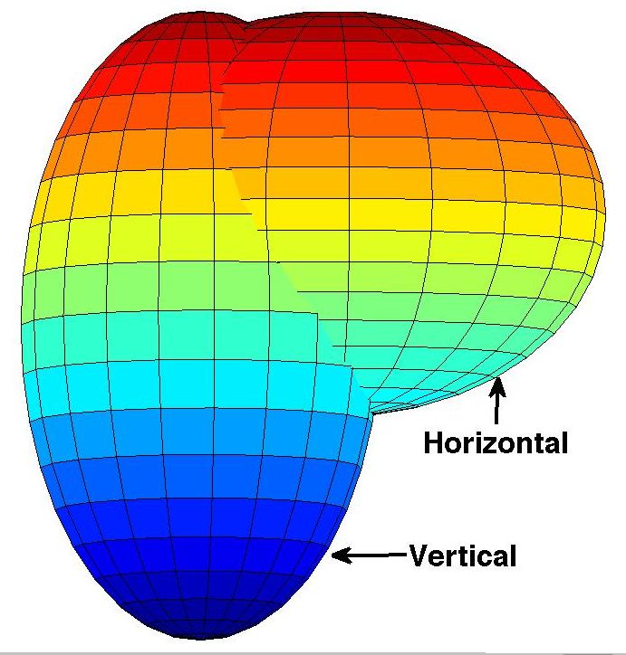
• An algorithm to find correspondences between a face              region with an ellipse of arbitrary size, shape, and orienta-
    detector’s output regions and the annotated face re-             tion, showing the approximate face region for each face in
    gions.                                                           the image. Compared to the traditional rectangular annota-
                                                                     tion of faces, ellipses are generally a better fit to face regions
  • Two separate rigorous and precise methods for evaluat-           and still maintain a simple parametric shape to describe the
    ing any algorithm’s performance on the data set. These           face. We discuss the details of the annotation process in
    two methods are intended for different applications.             Section 5. Note that our data set is amenable to any addi-
                                                                     tional annotations including facial landmarks and head pose
  • Source code for implementing these procedures.
                                                                     information, which would be beneficial for benchmarking
   We hope that our new data set, the proposed evaluation            the next generation of face detection algorithms.
scheme, and the publicly available evaluation software will             Next we discuss the origins and construction of our
make it easier to precisely compare the performance of al-           database.
gorithms, which will further prompt researchers to work on
more difficult versions of the face detection problem.               3. FDDB: Face Detection Data set and Bench-
   The report is organized as follows. In Section 2, we                  mark
discuss the challenges associated with comparing different
face detection approaches. In Section 3, we outline the con-            Berg et al. [2] created a data set that contains images
struction of our data set. Next, in Section 4, we describe a         and associated captions extracted from news articles (see
semi-automatic approach for removing duplicate images in             Figure 1). The images in this collection display large varia-
a data set. In Section 5, we present the details of the an-          tion in pose, lighting, background and appearance. Some of
notation process, and finally in Section 6, we present our           these variations in face appearance are due to factors such as
evaluation scheme.                                                   motion, occlusions, and facial expressions, which are char-
                                                                     acteristic of the unconstrained setting for image acquisition.
                                                                     The annotated faces in this data set were selected based on
2. Comparing face detection approaches
                                                                     the output of an automatic face detector. An evaluation of
   Based of the range of acceptable head poses, face detec-          face detection algorithms on the existing set of annotated
tion approaches can be categorized as                                faces would favor the approaches with outputs highly cor-
                                                                     related with this base detection algorithm. This property of
  • single pose: the head is assumed to be in a single, up-          the existing annotations makes them unsuitable for evaluat-
    right pose (frontal [24, 18, 26] or profile [21]);               ing different approaches for face detection. The richness of
                                                                     the images included in this collection, however, motivated
  • rotation-invariant: in-plane rotations of the head are
                                                                     us to build an index of all of the faces present in a subset of
    allowed [8, 19];
                                                                     images from this collection. We believe that benchmarking
  • multi-view: out-of-plane rotations are binned into a             face detection algorithms on this data set will provide good
    pre-determined set of views [7, 9, 12];                          estimates of their expected performance in unconstrained
                                                                     settings.
  • pose-invariant: no restrictions on the orientation of
    the head [16, 22].                                               3.1. Construction of the data set
   Moving forward from previous comparisons [28] of ap-
proaches that focus on limited head orientations, we intend                                      Near-
                                                                        Original                                          Ellipse
to evaluate different approaches for the most general, i.e.,                                    duplicate
                                                                       Collection                                         Fitting
the pose-invariant, face detection task.                                                        Detection
   One challenge in comparing face detection systems is the
                                                                     Figure 2. Outline of the labeling process. Semi-automatic ap-
lack of agreement on the desired output. In particular, while        proaches are developed for both of these steps.
many approaches specify image regions – e.g., rectangular
regions [26] or image patches with arbitrary shape [17] – as
                                                                        The images in Berg et al.’s data set were collected from
hypotheses for face regions, others idetify the locations of
                                                                     the Yahoo! news website,1 which accumulates news arti-
various facial landmarks such as the eyes [27]. Still others
                                                                     cles from different sources. Although different news or-
give an estimate of head pose [16] as well.
                                                                     ganizations may cover a news event independently of each
   The scope of this work is limited to the evaluation of
                                                                     other, they often share photographs from common sources
region-based output alone (although we intend to follow this
                                                                     such as the Associated Press or Reuters. The published
report in the near future with a similar evaluation of 3D pose
estimation algorithms). To this end, we annotate each face              1 http://news.yahoo.com

                                                                 2
Figure 1. Example images from Berg et al.’s data set.

photographs, however, may not be digitally identical to
each other because they are often modified (e.g., cropped
or contrast-corrected) before publication. This process has
led to the presence of multiple copies of near-duplicate im-
ages in Berg et al.’s data set. Note that the presence of such
near-duplicate images is limited to a few data collection do-
mains such as news photos and those on the internet, and
is not a characteristic of most practical face detection ap-
plication scenarios. For example, it is uncommon to find
near-duplicate images in a personal photo collection. Thus,
an evaluation of face detection algorithms on a data set with
multiple copies of near-duplicate images may not generalize
well across domains. For this reason, we decided to identify
and remove as many near duplicates from our collection as
possible. We now present the details of the duplicate detec-
tion.

4. Near-duplicate detection
    We selected a total of 3527 images (based on the chrono-
logical ordering) from the image-caption pairs of Berg et
al. [2]. Examining pairs for possible duplicates in this col-
lection in the naı̈ve fashion would require approximately
12.5 million annotations. An alternative arrangement would           Figure 3. Near-duplicate images. (Positive) The first two images
be to display a set of images and manually identify groups           differ from each other slightly in the resolution and the color and
of images in this set, where images in a single group are            intensity distributions, but the pose and expression of the faces are
                                                                     identical, suggesting that they were derived from a single photo-
near-duplicates of each other. Due to the large number of
                                                                     graph. (Negative) In the last two images, since the pose is differ-
images in our collection, it is unclear how to display all the
                                                                     ent, we do not consider them as near-identical images.
images simultaneously to enable this manual identification
of near-duplicates in this fashion.
    Identification of near-duplicate images has been stud-
ied for web search [3, 4, 5]. However, in the web search             was shown to perform well on a related problem of detect-
domain, scalability issues are often more important than             ing near-identical frames in news video databases. These
the detection of all near-duplicate images in the collec-            ARGs represent the compositional parts and part-relations
tion. Since we are interested in discovering all of the near-        of image scenes over several interest points detected in an
duplicates in our data set, these approaches are not directly        image. To compute a matching score between the ARGs
applicable to our task. Zhang et al. [29] presented a more           constructed for two different images, a generative model
computationally intensive approach based on stochastic at-           for the graph transformation process is employed. This ap-
tribute relational graph (ARG) matching. Their approach              proach has been observed to achieve high recall of near-

                                                                 3
duplicates, which makes it appropriate for detecting similar by a single exemplar from the cluster. In this process we
images in our data set. manually discovered 103 uniform clusters over seven iter-
As with most automatic approaches for duplicate detec- ations, with 682 images that were near-duplicates. Addi-
tion, this approach has a trade-off among false positives tional manual inspections were performed to find an addi-
and false negatives. To restrict the number of false posi- tional three cases of duplication.
tives, while maintaining a high true positive rate, we follow Next we describe our annotation of face regions.
an iterative approach (outlined in Algorithm 1) that alter-
nates between clustering and manual inspection of the clus- 5. Annotating face regions
ters. We cluster (steps 3-5 of Algorithm 1) using a spectral
graph-clustering approach [15]. Then, we manually label As a preliminary annotation, we drew bounding boxes
each non-singleton cluster from the preceding step as either around all the faces in 2845 images. From this set of anno-
uniform, meaning that it contains images that are all near tations, all of the face regions with height or width less than
duplicates of each other, or non-uniform, meaning that at 20 pixels were excluded, resulting in a total of 5171 face
least one pair of images in the cluster are not near duplicates annotations in our collection.
of each other. Finally, we replace each uniform cluster with
one of the images belonging to it.
For the clustering step, in particular, we construct a fully-
connected undirected graph G over all the images in the
collection, where the ARG-matching scores are used as
weights for the edges between each pair of images. Follow-
ing the spectral graph-clustering approach [15], we compute
the (unnormalized) Laplacian LG of graph G as
LG = diag(d) − WG , (1)
where d is the set of degrees of all the nodes in G, and WG
is the adjacency matrix of G. A projection of the graph G
into a subspace spanned by the top few eigenvectors of LG
provides an effective distance metric between all pairs of
nodes (images, in our case). We perform mean-shift clus-
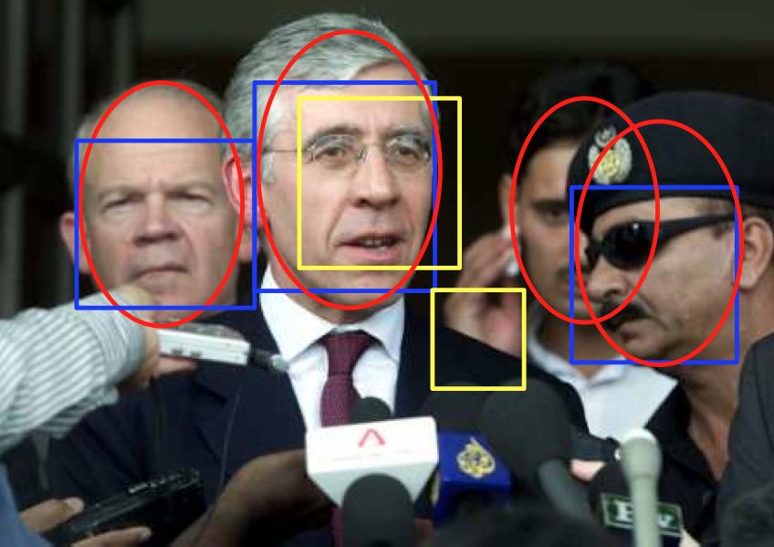
Figure 4. Challenges in face labeling. For some image regions,
tering with a narrow kernel in this projected space to obtain deciding whether or not it represents a “face” can be challeng-
clusters of images. ing. Several factors such as low resolution (green, solid), occlu-
sion (blue, dashed), and pose of the head (red, dotted) may make
Algorithm 1 Identifying near-duplicate images in a collec- this determination ambiguous.
tion
1: Construct a graph G = {V, E}, where V is the set of For several image regions, the decision of labeling them
images, and E are all pairwise edges with weights as as face regions or non-face regions remains ambiguous due
the ARG matching scores. to factors such as low resolution, occlusion, and head-pose
2: repeat (e.g., see Figure 4). One possible approach for handling
3: Compute the Laplacian of G, LG . these ambiguities would be to compute a quantitative mea-
4: Use the top m eigenvectors of LG to project each sure of the “quality” of the face regions, and reject the im-
image onto Rm . age regions with the value below a pre-determined thresh-
5: Cluster the projected data points using mean-shift old. We were not able, however, to construct a satisfactory
clustering with a small-width kernel. set of objective criteria for making this determination. For
6: Manually label each cluster as either uniform or non- example, it is difficult to characterize the spatial resolution
uniform. needed to characterize an image patch as a face. Similarly,
7: Collapse the uniform clusters onto their centroids, for occluded face regions, while a threshold based on the
and update G. fraction of the face pixels visible could be used as a crite-
8: until none of the clusters can be collapsed. rion, it can be argued that some parts of the face (e.g., eyes)
are more informative than other parts. Also, note that for
Using this procedure, we were able to arrange the im- the current set of images, all of the regions with faces look-
ages according to their mutual similarities. Annotators were ing away from the camera have been labeled as non-face
asked to identify clusters in which all images were derived regions. In other words, the faces with the angle between
from the same source. Each of these clusters was replaced the nose (specified as radially outward perpendicular to the
4
head) and the ray from the camera to the person’s head is
less than 90 degrees. Estimating this angle precisely from                                Top of the head
an image is difficult.
    Due to the lack of an objective criterion for including (or
excluding) a face region, we resort to human judgments for
                                                                                                                                        1 unit
this decision. Since a single human decision for determin-
ing the label for some image regions is likely to be inconsis-
tent, we used an approach based on the agreement statistics
among multiple human annotators. All of these face regions
were presented to different people through a web interface
to obtain multiple independent decisions about the validity
of these image regions as face regions. The annotators were                                                                             1 unit
instructed to reject the face regions for which neither of the
two eyes (or glasses) were visible in the image. They were
also requested to reject a face region if they were unable
to (qualitatively) estimate its position, size, or orientation.                                    Chin
The guidelines provided to the annotators are described in
Appendix A.                                                               Figure 6. Guidelines for drawing ellipses around face regions.
                                                                          The extreme points of the major axis of the ellipse are respectively
5.1. Elliptical Face Regions                                              matched to the chin and the topmost point of the hypothetical ver-
                                                                          tical ellipsoid used for approximating the human head (see Fig-
                                                                          ure 5). Note that this ellipse does not include the ears. Also, for a
                                                                          non-frontal face, at least one of the lateral extremes (left or right)
                                                                          of this ellipse are matched to the boundary between the face re-
                                                                          gion and the corresponding (left or right) ear. The details of our
                                                                          specifications are included in Appendix A.

Figure 5. Shape of a human head. The shape of a human head
(left) can be approximated as the union of two ellipsoids (right).
We refer to these ellipses as vertical and horizontal ellipsoids.

    As shown in Figure 5,2 the shape of a human head can
be approximated using two three-dimensional ellipsoids.
We call these ellipsoids the vertical and horizontal ellip-
soids. Since the horizontal ellipsoid provides little informa-
tion about the features of the face region, we estimate a 2D
ellipse for the orthographic projection of the hypothesized
vertical ellipsoid in the image plane. We believe that the re-
sulting representation of a face region as an ellipse provides            Figure 7. Sample Annotations. The two red ellipses specify the
a more accurate specification than a bounding box without                 location of the two faces present in this image. Note that for a non-
introducing any additional parameters.                                    frontal face (right), the ellipse traces the boundary between the
    We specified each face region using an ellipse parame-                face and the visible ear. As a result, the elliptical region includes
terized by the location of its center, the lengths of its major           pixels that are not a part of the face.
and minor axes, and its orientation. Since a 2D orthographic
projection of the human face is often not elliptical, fitting
an ellipse around the face regions in an image is challeng-               data set, the human annotators are instructed to follow the
ing. To make consistent annotations for all the faces in our              guidelines shown in Figure 6. Figure 7 shows some sample
  2 Reproduced with permission from Dimitar Nikolov, Lead Animator,       annotations. The next step is to produce a consistent and
Haemimont Games.                                                          reasonable evaluation criterion.

                                                                      5
6. Evaluation
    To establish an evaluation criterion for detection algo-
rithms, we first specify some assumptions we make about
their outputs. We assume that

  • A detection corresponds to a contiguous image region.

  • Any post-processing required to merge overlapping or
    similar detections has already been done.

  • Each detection corresponds to exactly one entire face,
    no more, no less. In other words, a detection cannot
    be considered to detect two faces at once, and two de-
    tections cannot be used together to detect a single face.
    We further argue that if an algorithm detects multiple             Figure 8. Matching detections and annotations. In this image, the
    disjoint parts of a face as separate detections, only one          ellipses specify the face annotations and the five rectangles denote
    of them should contribute towards a positive detection             a face detector’s output. Note that the second face from left has
    and the remaining detections should be considered as               two detections overlapping with it. We require a valid matching
    false positives.                                                   to accept only one of these detections as the true match, and to
                                                                       consider the other detection as a false positive. Also, note that the
    To represent the degree of match between a detection di            third face from the left has no detection overlapping with it, so no
and an annotated region lj , we employ the commonly used               detection should be matched with this face. The blue rectangles
ratio of intersected areas to joined areas:                            denote the true positives and yellow rectangles denote the false
                                                                       positives in the desired matching.
                           area(di ) ∩ area(lj )
           S(di , lj ) =                         .          (2)
                           area(di ) ∪ area(lj )                                         d1                  d2                 Detections

    To specify a more accurate annotation for the image re-
gions corresponding to human faces than is obtained with                 Max-Flow
the commonly used rectangular regions, we define an ellip-
tical region around the pixels corresponding to these faces.
While this representation is not as accurate as a pixel-level               l1                     l2                      l3      Labels
annotation, it is a clear improvement over the rectangular
annotations in existing data sets.
    To facilitate manual labeling, we start with an automated                            n1                  n2                  No Match
guess about face locations. To estimate the elliptical bound-
ary for a face region, we first apply a skin classifier on the         Figure 9. Maximum weight matching in a bipartite graph. We
image pixels that uses their hue and saturation values. Next,          make an injective (one-to-one) mapping from the set of detected
the holes in the resulting face region are filled using a flood-       image regions di to the set of image regions li annotated as face
fill implementation in MATLAB. Finally, a moments-based                regions. The property of the resulting mapping is that it maximizes
fit is performed on this region to obtain the parameters of            the cumulative similarity score for all the detected image regions.
the desired ellipse. The parameters of all of these ellipses
are manually verified and adjusted in the final stage.
                                                                          Let L be the set of annotated face regions (or labels) and
                                                                       D be the set of detections. We construct a graph G with
6.1. Matching detections and annotations
                                                                       the set of nodes V = L ∪ D. Each node di is connected
   A major remaining question is how to establish a cor-               to each label lj ∈ L with an edge weight wij as the score
respondence between a set of detections and a set of an-               computed in Equation 2. For each detection di ∈ D, we
notations. While for very good results on a given image,               further introduce a node ni to correspond to the case when
this problem is easy, it can be subtle and tricky for large            this detection di has no matching face region in L.
numbers of false positives or multiple overlapping detec-                 A matching of detections to face regions in this graph
tions (see Figure 8 for an example). Below, we formulate               corresponds to the selection of a set of edges M ⊆ E. In
this problem of matching annotations and detections as find-           the desired matching of nodes, we want every detection to
ing a maximum weighted matching in a bipartite graph (as               be matched to at most one labeled face region, and every
shown in Figure 9).                                                    labeled face region to be matched to at most one detection.

                                                                   6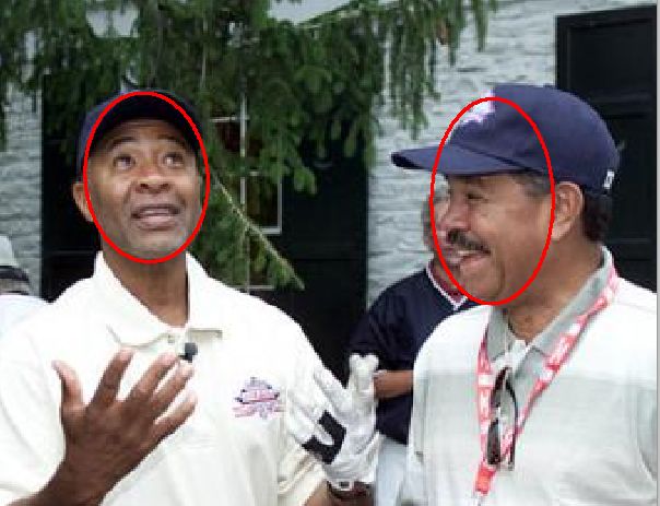
Note that the nodes nk have a degree equal to one, so they           7. Experimental Setup
can be connected to at most one detection through M as
well. Mathematically, the desired matching M maximizes                  For an accurate and useful comparison of different ap-
the cumulative matching score while satisfying the follow-           proaches, we recommend a distinction based on the training
ing constraints:                                                     data used for estimating their parameters. In particular, we
                                                                     propose the following experiments:
                                       M
         ∀d ∈ D, ∃l ∈ {L ∪ N },     d −→ l                (3)
                                       M           0 M
                                                                     EXP-1: 10-fold cross-validation
           ∀l ∈ L, @d, d0 ∈ D,      d −→ l ∧ d −→ l       (4)
                                                                     For this experiment, a 10-fold cross-validation is performed
    The determination of the minimum weight matching in a            using a fixed partitioning of the data set into ten folds.3 The
weighted bipartite graph has an equivalent dual formulation          cumulative performance is reported as the average curve of
as finding the solution of the minimum weighted (vertex)             the ten ROC curves, each of which is obtained for a different
cover problem on a related graph. This dual formulation              fold as the validation set.
is exploited by the Hungarian algorithm [11] to obtain the
solution for the former problem. For a given image, we em-           EXP-2: Unrestricted training
ploy this method to determine the matching detections and
ground-truth annotations. The resulting similarity score is          For this experiment, data outside the FDDB data set is
used for evaluating the performance of the detection algo-           permitted to be included in the training set. The above-
rithm on this image.                                                 mentioned ten folds of the data set are separately used as
                                                                     validation sets to obtain ten different ROC curves. The cu-
6.2. Evaluation metrics                                              mulative performance is reported as the average curve of
                                                                     these ten ROC curves.
   Let di and vi denote the ith detection and the correspond-
ing matching node in the matching M obtained by the al-
                                                                     8. Benchmark
gorithm described in Section 6.1, respectively. We propose
the following two metrics for specifying the score yi for this          For a proper use of our data set, we provide the imple-
detection:                                                           mentation (C++ source code) of the algorithms for matching
                                                                     detections and annotations (Section 6.1), and computing the
  • Discrete score (DS) : yi = δS(di ,vi )>0.5 .                     resulting scores (Section 6.2) to generate the performance
                                                                     curves at http://vis-www.cs.umass.edu/fddb/
  • Continuous score (CS): yi = S(di , vi ).
                                                                     results.html. To use our software, the user needs to
    For both of these choice of scoring the detections, we           create a file containing a list of the output of this detector.
recommend analyzing the Receiver Operating Character-                The format of this input file is described in Appendix B.
istic (ROC) curves to compare the performance of differ-                In Figure 10, we present the results for the following ap-
ent approaches on this data set. Although comparing the              proaches for the above-mentioned EXP-2 experimental set-
area under the ROC curve is equivalent to a non-parametric           ting:
statistical hypothesis test (Wilcoxon signed-rank test), it is          • Viola-Jones detector [26] – we used the OpenCV4 im-
plausible that the cumulative performances of none of the                 plementation of this approach. We set the scale-factor
compared approaches is better than the rest with statistical              and minimum number of neighbors parameters to 1.2
significance. Furthermore, it is likely that for some range               and 0, respectively.
of performance, one approach could outperform another,
whereas the relative comparison is reversed for a different             • Mikolajczyk’s face detector [14] 5 – we set the param-
range. For instance, one detection algorithm might be able                eter for the minimum distance between eyes in a de-
to maintain a high level of precision for low recall values,              tected face to 5 pixels.
but the precision drops sharply after a point. This trend may
suggest that this detector would be useful for application              • Kienzle et al.’s [10] face detection library (fdlib 6 ).
domains such as biometrics-based access controls, which
may require high precision values, but can tolerate low re-            3 The ten folds used in the proposed experiments are available at http:

call levels. The same detector may not be useful in a setting        //vis-www.cs.umass.edu/fddb/FDDB-folds.tgz
                                                                       4 http://sourceforge.net/projects/opencvlibrary/
(e.g., surveillance) that would requires the retrieval of all          5 http://www.robots.ox.ac.uk/∼vgg/research/
the faces in an image or scene. Hence, the analysis of the           affine/face detectors.html
entire range of ROC curves should be done for determining              6 http://www.kyb.mpg.de/bs/people/kienzle/fdlib/

the strengths of different approaches.                               fdlib.htm

                                                                 7
are limited to the approaches that were developed for frontal
                                                                       face detection. This limitation is due to the unavailability
                                                                       of a public implementation of multi-pose or pose-invariant
                                                                       face detection system. Nevertheless, the new benchmark in-
                                                                       cludes more challenging examples of face appearances than
                                                                       the previous benchmarks. We hope that our benchmark will
                                                                       further prompt researchers to explore new research direc-
                                                                       tions in face detection.

                                                                       Acknowledgements
                                                                          We thank Allen Hanson, Andras Ferencz, Jacqueline
                                                                       Feild, and Gary Huang for useful discussions and sug-
                                                                       gestions. This work was supported by the National Sci-
                                                                       ence Foundation under CAREER award IIS-0546666. Any
                                                                       opinions, findings and conclusions or recommendations ex-
                                                                       pressed in this material are the authors’ and do not neces-
                                                                       sarily reflect those of the sponsor.
       (a) ROC curves based on discrete score (DS)
                                                                       References
                                                                        [1] A. S. Abdallah, M. A. El-nasr, and A. L. Abbott. A new color
                                                                            image database for benchmarking of automatic face detec-
                                                                            tion and human skin segmentation techniques, to appear. In
                                                                            International Conference on Machine Learning and Pattern
                                                                            Recognition, 2007. 1
                                                                        [2] T. L. Berg, A. C. Berg, J. Edwards, M. Maire, R. White,
                                                                            Y. W. Teh, E. Learned-Miller, and D. A. Forsyth. Names and
                                                                            faces in the news. In IEEE Conference on Computer Vision
                                                                            and Pattern Recognition, volume 2, pages 848–854, 2004. 2,
                                                                            3
                                                                        [3] O. Chum, J. Philbin, M. Isard, and A. Zisserman. Scalable
                                                                            near identical image and shot detection. In ACM Interna-
                                                                            tional Conference on Image and Video Retrieval, pages 549–
                                                                            556, New York, NY, USA, 2007. ACM. 3
                                                                        [4] O. Chum, J. Philbin, and A. Zisserman. Near duplicate image
                                                                            detection: min-hash and tf-idf weighting. In British Machine
                                                                            Vision Conference, 2008. 3
                                                                        [5] J. J. Foo, J. Zobel, R. Sinha, and S. M. M. Tahaghoghi. De-
                                                                            tection of near-duplicate images for web search. In ACM In-
      (b) ROC curves based on continuous score (CS)                         ternational Conference on Image and Video Retrieval, pages
                                                                            557–564, New York, NY, USA, 2007. ACM. 3
Figure 10. FDDB baselines. These are the ROC curves for differ-         [6] R.-L. Hsu, M. Abdel-Mottaleb, and A. Jain. Face detection
ent face detection algorithms. Both of these scores (DS and CS)             in color images. IEEE Transactions on Pattern Analysis and
are described in Section 6.2, whereas the implementation details            Machine Intelligence, 24(5):696–706, May 2002. 1
of these algorithms are included in Section 8.
                                                                        [7] C. Huang, H. Ai, Y. Li, and S. Lao. High-performance rota-
                                                                            tion invariant multiview face detection. IEEE Transactions
                                                                            on Pattern Analysis and Machine Intelligence, 29(4):671–
   As seen in Figure 10, the number of false positives ob-                  686, 2007. 2
tained from all of these face detection systems increases               [8] B. H. Jeon, S. U. Lee, and K. M. Lee. Rotation invari-
rapidly as the true positive rate increases. Note that the per-             ant face detection using a model-based clustering algorithm.
formances of all of these systems on the new benchmark are                  In IEEE International Conference on Multimedia and Expo,
much worse than those on the previous benchmarks, where                     volume 2, pages 1149–1152 vol.2, 2000. 2
they obtain less than 100 false positives at a true positive            [9] M. J. Jones and P. A. Viola. Fast multi-view face detection.
rate of 0.9. Also note that although our data set includes im-              Technical Report TR2003-96, Mitsubishi Electric Research
ages of frontal and non-frontal faces, the above experiments                Laboratories, August 2003. 2

                                                                   8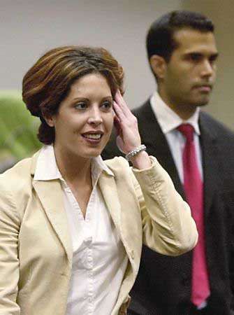
[10] W. Kienzle, G. H. Bakır, M. O. Franz, and B. Schölkopf.             [25] http://mplab.ucsd.edu.                The MPLab GENKI
     Face detection — efficient and rank deficient. In L. K. Saul,             Database, GENKI-4K Subset. 1
     Y. Weiss, and L. Bottou, editors, Advances in Neural In-             [26] P. A. Viola and M. J. Jones. Robust real-time face detec-
     formation Processing Systems, pages 673–680, Cambridge,                   tion. International Journal of Computer Vision, 57(2):137–
     MA, 2005. MIT Press. 7                                                    154, May 2004. 2, 7
[11] H. W. Kuhn. The Hungarian method for the assignment prob-            [27] P. Wang and Q. Ji. Multi-view face and eye detection using
     lem. Naval Research Logistics Quarterly, 2:83–97, 1955. 7                 discriminant features. Computer Vision and Image Under-
[12] S. Z. Li, L. Zhu, Z. Zhang, A. Blake, H. Zhang, and H. Shum.              standing, 105(2):99–111, 2007. 2
     Statistical learning of multi-view face detection. In European
                                                                          [28] M.-H. Yang, D. J. Kriegman, and N. Ahuja. Detecting faces
     Conference on Computer Vision, pages 67–81, London, UK,
                                                                               in images: A survey. IEEE Transactions on Pattern Analysis
     2002. Springer-Verlag. 2
                                                                               and Machine Intelligence, 24(1):34–58, 2002. 1, 2
[13] A. Loui, C. Judice, and S. Liu. An image database for bench-
                                                                          [29] D.-Q. Zhang and S.-F. Chang. Detecting image near-
     marking of automatic face detection and recognition algo-
                                                                               duplicate by stochastic attributed relational graph matching
     rithms. In IEEE International Conference on Image Pro-
                                                                               with learning. In ACM International Conference on Multi-
     cessing, volume 1, pages 146–150 vol.1, Oct 1998. 1
                                                                               media, pages 877–884, 2004. 3
[14] K. Mikolajczyk, C. Schmid, and A. Zisserman. Human de-
     tection based on a probabilistic assembly of robust part de-
     tectors. In European Conference on Computer Vision, pages            A. Guidelines for annotating faces using el-
     69–82, 2004. 7                                                          lipses
[15] A. Y. Ng, M. I. Jordan, and Y. Weiss. On spectral clustering:
     Analysis and an algorithm. In Advances in Neural Informa-                To ensure consistency across multiple human annotators,
     tion Processing Systems, pages 849–856. MIT Press, 2001.             we developed a set of instructions (shown in Figure 11).
     4                                                                    These instructions specify how to use facial landmarks to
[16] M. Osadchy, Y. LeCun, and M. L. Miller. Synergistic face             fit an ellipse depending on the pose of the head. Figure 12
     detection and pose estimation with energy-based models.
                                                                          presents an illustration of the resulting ellipses on line draw-
     Journal of Machine Learning Research, 8:1197–1215, 2007.
     2
                                                                          ings of a human head. The annotators were futher instructed
[17] J. Rihan, P. Kohli, and P. Torr. OBJCUT for face detection. In       to follow a combination of these guidelines to fit ellipses to
     Indian Conference on Computer Vision, Graphics and Image             faces with complex head poses.
     Processing, pages 576–584, 2006. 2                                       The illustrations shown in Figure 12 use faces with neu-
[18] H. A. Rowley, S. Baluja, and T. Kanade. Neural network-              tral expressions. A presence of some expressions such as
     based face detection. IEEE Transactions on Pattern Analysis          laughter, often changes the shape of the face significantly.
     and Machine Intelligence, 20(1):23–38, January 1998. 1, 2            Moreover, even bearing a neutral expression, some faces
[19] H. A. Rowley, S. Baluja, and T. Kanade. Rotation invariant           have shapes markedly different from the average face shape
     neural network-based face detection. In IEEE Conference on           used in these illustrations. Such faces (e.g., faces with
     Computer Vision and Pattern Recognition, page 38, Wash-              square-jaw or double-chin) are difficult to approximate us-
     ington, DC, USA, 1998. IEEE Computer Society. 2
                                                                          ing ellipses. To annotate faces with such complexities, the
[20] H. Schneiderman and T. Kanade. Probabilistic modeling of
                                                                          annotators were instructed to refer to the following guide-
     local appearance and spatial relationships for object recogni-
     tion. In IEEE Conference on Computer Vision and Pattern              lines:
     Recognition, page 45, Washington, DC, USA, 1998. IEEE
     Computer Society. 1                                                    • Facial expression. Since the distance from the eyes to
[21] H. Schneiderman and T. Kanade. A statistical method for 3d               the chin in a face with facial expression is not necessar-
     object detection applied to faces and cars. In IEEE Confer-              ily equal to the distance between the eyes and the top
     ence on Computer Vision and Pattern Recognition, volume 1,               of the head (an assumption made for the ideal head),
     pages 746–751 vol.1, 2000. 1, 2                                          the eyes do not need to be aligned to the minor axis for
[22] M. Seshadrinathan and J. Ben-Arie. Pose invariant face de-               this face.
     tection. In Video/Image Processing and Multimedia Commu-
     nications, 2003. 4th EURASIP Conference focused on, vol-
                                                                            • Double-chin. For faces with a double chin, the aver-
     ume 1, pages 405–410 vol.1, July 2003. 2
                                                                              age of the two chins is considered as the lowest point
[23] P. Sharma and R. Reilly. A colour face image database for
     benchmarking of automatic face detection algorithms. In
                                                                              of the face, and is matched to the bottom extreme of
     EURASIP Conference focused on Video/Image Processing                     the major axis of the ellipse.
     and Multimedia Communications, volume 1, pages 423–428
     vol.1, July 2003. 1                                                    • Square jaw. For a face with a square jaw, the el-
[24] K.-K. Sung and T. Poggio. Example-based learning for view-               lipse traces the boundary between the face and the ears,
     based human face detection. IEEE Transactions on Pattern                 while some part of the jaws may be excluded from the
     Analysis and Machine Intelligence, 20(1):39–51, 1998. 1, 2               ellipse.

                                                                      9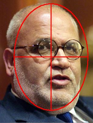
Pose?

                 Frontal                             Profile                         Tilted back/front

  1. Make the major axis                           1. Make the major axis                            1. Make the major axis
  parallel to the nose.                            parallel to the projection of                     parallel to the nose.
                                                   the nose onto the face.
  2. Match the chin to the                                                                           2. Ensure that the ellipse
  bottom end of the major                          2. Place the visible eye on                       traces the boundary
  axis of the ellipse.                             the minor axis.                                   between the ears and the
                                                                                                     face.
  3. Make the eyes align                           3. Include the entire chin
  with the minor axis of the                       in the ellipse.
  ellipse.
                                                   4. Ensure that the ellipse
  4. Ensure that the ellipse                       traces the boundary
  traces the boundary                              between the visible ear                              Tilt direction?
  between the ears and the                         and the face.
  face.

                                                                                          Back                                Front

                                                                                1. Ensure that the ellipse              1. Ensure that the
                                                                                traces the top of the                   ellipse traces the jaw-
                                                                                head.                                   line.

Figure 11. Procedure for drawing ellipses around an average face region. The annotators were instructed to follow this flowchart to draw
ellipses around the face regions. The annotation steps are a little different for different poses. Here, we present the steps for three canonical
poses: frontal, profile and tilted back/front. The annotators were instructed to use a combination of these steps for labeling faces with
derived, intermediate head poses. For instance, to label a head facing slightly towards its right and titled back, a combination of the steps
corresponding to the profile and tilted-back poses are used.

           Top of the head                                  Top of the head                                    Top of the head

                                          1 unit                                            1 unit                                          1 unit

                                          1 unit                                            1 unit                                          1 unit

                 Chin                                              Chin                                              Chin

Figure 12. Illustrations of ellipse labeling on line drawings of human head. The black curves show the boundaries of a human head in
frontal (left), profile (center), and tilted-back (right) poses. The red ellipses illustrate the desired annotations as per the procedure shown
in Figure 11. Note that these head shapes are approximations to an average human head, and the shape of an actual human head may
deviate from this mean shape. The shape of a human head may also be affected by the presence of factors such as emotions. The guidelines
on annotating face regions influenced by these factors are specified in Appendix A.

  • Hair. Ignore the hair and fit the ellipse around the hy-                    • Occlusion. Hypothesize the full face behind the oc-
    pothetical bald head.                                                         cluding object, and match all of the visible features.

                                                                       10
Figure 13. Illustrations of labeling for complex face appearances. These images show example annotations for human heads with shapes
different from an average human head due to the presence of facial expression, double chin, square jaw, hair-do, and occlusion, respectively.
Figure 13 shows some example annotations for complex ...
face shapes. name of the ith image
number of faces in the ith image = m
B. Data formats face f1
face f2
The original set of images can be down- ...
loaded as originalPics.tar.gz from face fm
http://tamaraberg.com/faceDataset/. ...
Uncompressing this tar-file organizes the images as Table 1. Format used for the specification of annotations and
originalPics/year/month/day/big/*.jpg. detections .
The ten folds described in the EXP-1 experiments (Sec-
tion 7) are available at http://vis-www.cs.umass.
edu/fddb/FDDB-folds.tgz. Uncompressing the Each face region is represented as a 5-tuple
FDDB-folds.tgz file creates a directory FDDB-folds,
(x, y, w, h, s), (6)
which contains files with names: FDDB-fold-xx.txt
and FDDB-fold-xx-ellipseList.txt, where xx where x, y are the coordinates of the top-left corner;
= {01, 02, ..., 10} represents the fold-index. w and h are the width and height; and s ∈ {−∞, ∞}
Each line in the FDDB-fold-xx.txt file is the confidence score associated with the detection of
specifies a path to an image in the above- this rectangular region.
mentioned data set. For instance, the entry
2002/07/19/big/img 130 corresponds to • Elliptical regions
originalPics/2002/07/19/big/img 130.jpg. Each face region is represented as a 6-tuple
The corresponding annotations are included in the file
FDDB-fold-xx-ellipseList.txt. These anno- (ra , rb , θ, cx , cy , s), (7)
tations are specified according to the format shown in
Table 1. Each of the annotation face regions are represented where ra and rb refer to the half-length of the major
as an elliptical region, which is denoted by a 6-tuple and minor axes; θ is the angle of the major axis with
the horizontal axis; and cx and cy are the x and y coor-
(ra , rb , θ, cx , cy , 1), (5) dinates of the center; and s ∈ {−∞, ∞} is the confi-
dence score associated with the detection of this ellip-
where ra and rb refer to the half-length of the major and mi- tical region.
nor axes; θ is the angle of the major axis with the horizontal
axis; and cx and cy are the x and y coordinates of the center Note that the order of images in the output file
of this ellipse. is expected to be the same as the order in the file
The detection output should also follow the format de- annotatedList.txt.
scribed in Table 1. The representation of each of the de-
tected face regions, however, could either be denoted using
a rectangle or an ellipse. The exact specification for these
two types of representations is as following:
• Rectangular regions
11You can also read