Field Setup Guide 2020-2021 FIRST Tech Challenge - Rev 1.3 - FIRST Inspires
←
→
Page content transcription
If your browser does not render page correctly, please read the page content below
2020-2021 FIRST® Tech Challenge
    Field Setup Guide
                                  Rev 1.3

              1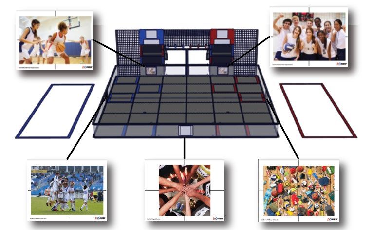
This guide contains instructions for setting up the Field Elements for the
                       2020-2021 FIRST® Tech Challenge Game

                             ULTIMATE GOALSM Presented by Qualcomm®

       Read through all the instructions and take a parts inventory before
             you begin to assemble and setup the game elements!

REVISION HISTORY
Rev.                       Date       Description
1.0                        8/26/20    Initial Release
1.1                        9/1/20     Added dimensions for vision images
1.2                        9/4/20     Added pics of navigation image placement
1.3                        10/26/20   Update cable tie for Power Shot Assemblies

TOOLS NEEDED
Component                                QTY                                       Part Photo

       Safety Equipment                As Needed

          Utility Knife                    1

              File                         1

            Scissors                       1

        Diagonal Cutters                   1

         Tape Measure                      1

         Color Printer                     1

                                                  2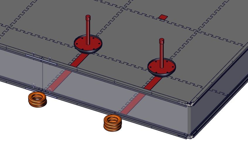
FULL FIELD REQUIREMENTS
   Component                       Part #                   QTY   Part Photo

 FIRST Tech Challenge             am-0481b
                                                             1
    Field Perimeter               or similar

                                  am-2499
  5/8” Gray Soft Tiles                                      36
                                  or similar

Competition Field Components
     Component                     Part #                   QTY   Part Photo

 Red Tower Goal with     See Field Assembly Guide for
                                                             1
     Power Shot             assembly instructions.

                                                        3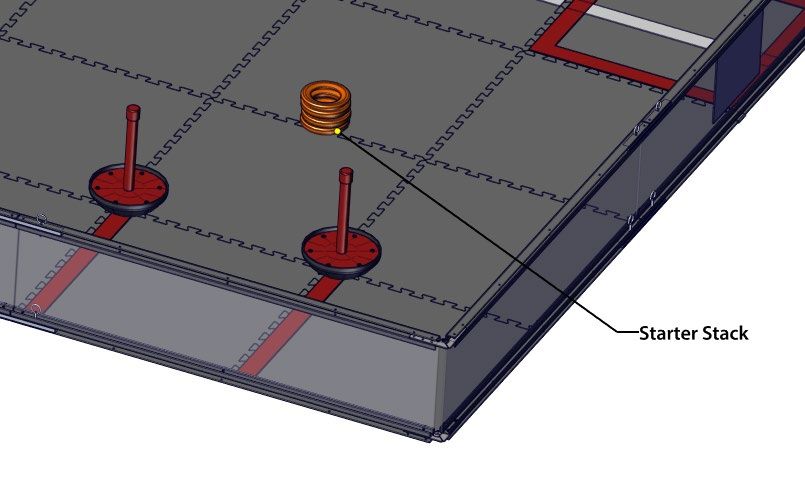
Blue Tower Goal with   See Field Assembly Guide for
                                                          1
     Power Shot           assembly instructions.

                       See Field Assembly Guide for
 Blue Wobble Goal                                         2
                          assembly instructions.

                       See Field Assembly Guide for
 Red Wobble Goal                                          2
                          assembly instructions.

                                                      4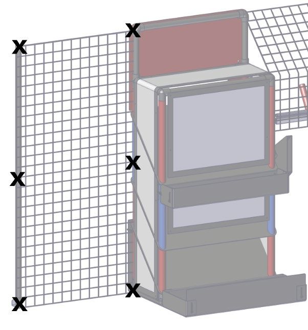
Side Net             am-4292          3

     Side Net Pipe           am-4337          2

  Side Net Lower Clip        am-4275          2

  Side Net Cable Ties        am-1552          20

      Game Piece             am-4300          20

 2” “Red” Gaffers Tape       am-2946   as needed

2” “Electric Blue” Gaffers
                             am-2947       as needed
           Tape

                                       5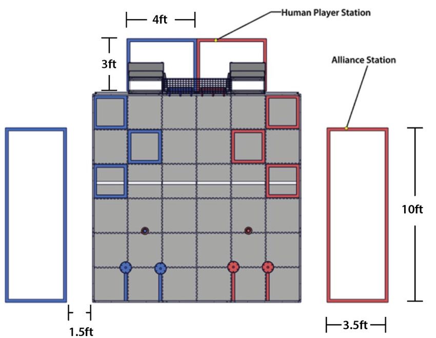
2” “White” Gaffers Tape           am-2945               as needed

Cardstock for Navigation
         Image              White 8.5x11” or A4
                                                           10
  (Printed from FIRST         (international)
   Resource Library)

     Velcro® Dots          Roughly ¾” diameter or
                                                         1 pack
                                   larger

 Clear Page Protection        Similar to Staples
                                                           7
        Sleeves                  P/N 40713

                                                    6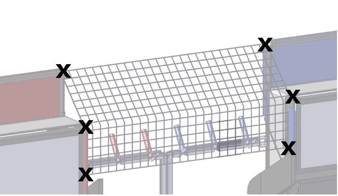
Part 1: Setting up the Floor and Field Perimeter
   Step 1-1: Lay the tiles with the smooth surface facing           Step 1-2: Critical Mandatory Step: Trim all outer tabs
   up in a 6x6 grid pattern.                                        from the 20 Soft Tiles on the outside edges of the field.

    NOTE: Lay the tiles out and mark the outer edge to be
    cut. Use a sharp utility knife and a straight edge or a band
    saw (if available) to get a smooth clean edge.

   NOTE: If using the AndyMark Field Perimeter, ensure that straps are installed to keep walls in place during game play.

Step 1-3: Note that there are several FIRST Tech Challenge Perimeter wall designs. The wall designs fall into two
categories. The smooth/non-cavity sides should face towards the inside of the Playing Field as shown in the illustration.

 Perimeter                     Wall Design Categories                                           Wall Height
 AndyMark (current)            Smooth on one side and an open cavity on the other side          12.125”
 IFI Perimeter                 Smooth on one side and an open cavity on the other side          11.5”
 Logo Loc Perimeter            Symmetrical inside and outside surfaces                          12.375”

                                                               7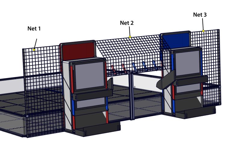
Part 2: General Layout and Orientation

                      MATCH TIMER
                      DISPLAY TABLE
    BLUE ALLIANCE

                                         RED ALLIANCE
                         AUDIENCE

                            8
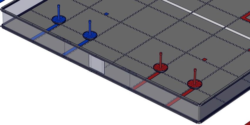
Part 3: Tower Goal Placement
On the official playing field, the Blue and Red Tower Goals are located outside the perimeter wall opposite
the audience. The two Power Shot Assemblies meet at the center of the rear perimeter wall. Both Power
Shot Assemblies and Return Racks should be on the side of the Tower Goal closest to the center.

The Power Shot Assemblies should be placed as close together as possible and secured together with two
cable ties. One at the top and one at the bottom of the assemblies.

                                                          Cable Ties

                                                    9
Protective Net Installation
Each field requires two net poles and clips, and 3 Side Nets.
Attach two poles on the far corner of the field. The Net Clip sits under the field perimeter and the long end
will go inside the pole.

Use a cable tie to secure each pole to the top rail.

                                                       10
Use cable ties to secure each of the 3 nets to the poles and Tower Goal Structure. The net should be tight and not
allow Rings to pass through any gaps.
Note: Recommended cable tie locations
are shown above with an X. Additional ties
may be used to ensure the net remains
tight and even throughout the
competition.
11Part 4: Tape Lines
Tape lines for the field are as shown. There is also a need for a Referee Question Box close to the field area.
Drivers & Human Player Stations
Drivers Stations are 10ft wide x 3.5ft deep and the Human Player Stations are 4ft wide by 3ft deep. When viewed from
the audience, the Blue Driver Station and the Blue Human Player Station are on the left side. The Driver Stations are
located 1.5ft (18 inches) away from the field perimeter and the Human Player Station is directly behind the Tower
Goal.
AUDIENCE
12On-Field Lines
All lines on and around the field are made with 2” wide white, red or blue Gaffers Tape.
Launch Line
The Launch Line is a 2” wide white gaffers tape line extending from the Blue Alliance wall to the Red Alliance wall. The
line can be a continuous line or have breaks at each tile section. The front edge of the Launch Line should measure
approximately 80” to the Audience Perimeter Wall
Target Zone Goals
The Target Zone Goals are approximately 22.75” by 22.75” square areas of the field marked by 2” wide Red or Blue
Gaffers tape on the inside edge of the tile square. Red squares are closest to the Red Alliance and Blue squares are
closest to the Blue Alliance.
13Starter Stack Areas
The starter stack areas are to be marked with an approximately 2x2” square piece of Red or Blue Gaffers Tape.
The markers are located on the front edge of the tile in the 3rd row back and 2nd column from the side wall. The marker
is centered on the tile. The Red marker will be located on the side closest to the Red Alliance Station and the Blue
marker will be located closest to the Blue Alliance Station.
Start Line
The Start Lines are approximately 22.75” long marked by 2” wide Red or Blue Gaffers tape on the edge of the
perimeter square. Red lines are placed on the inside tile edges closest to the Red Alliance and Blue lines are placed on
the inside tile edges closest to the Blue Alliance.
Referee Question Box
The Referee Question Box is a place where Teams can ask questions of the Referees after a
Match.
The Referee Question Box must be placed in the Competition Area in a location where it will not
interfere with the current running Matches, but close enough that the Referees will be able to
see a student waiting at the Question Box. The Question Box can be as simple as a 3ft Gaffers
Tape square on the floor.
14Part 5: Wobble Goal Placement
For pre-match setup, the Wobble Goals are placed on the field as shown. Each goal will be located at the
end of a Start Line.
15Part 6: Navigation Image Placement
Step 6-1: Download the Navigation Image file, along Step 6-2: Print the downloaded images in color, not
with ULTIMATE GOAL logo template. found on the FIRST greyscale, on 8.5x11” or A4 White Cardstock. The Print
Tech Challenge Game and Season Info Page: resolution must be at least 300DPI.
https://www.firstinspires.org/resource-library/ftc/game-
and-season-info
Step 6-3: Place the navigation images in the plastic Step 6-4: Use Velcro dots in the top corners of the
sleeves. The image with the logos will face outward, navigation target to secure to the field perimeter.
while the navigation target image will face inward.
Step 6-5: There are 5 Navigation Images are placed around the field as shown. Each image has lines around the edge
indicating vertical and horizontal center. Each image also has text with its placement location. The Front and Side
images will have a Game Changers graphic on the reverse side.
16Step 6-6: The field perimeter should measure approximately 141 inches from inside wall to inside wall. Navigation
Images should always be placed as follows:
Images on the Sides Walls
• The Navigation Image vertical center line should be centered on the field perimeter approximately 70.5
inches from the inside face of the far wall.
• The Navigation Image horizontal center line should measure 6.375 inches to the floor (5.75 inches from the
top of the tile).
17Images on the Tower Goal
• Images are placed in sleeves directly on the front face of the Tower Goal.
• The Navigation Image vertical center line should be centered on the Tower Goal approximately 12 inches
from the edge of the front flap of the Corral
• The Navigation Image horizontal center line measure 6.375 inches to the floor.
• The Navigation Image vertical center line should measure approximately 35.5” to the inside of the side
wall.
18Images on the Audience Wall
• The Navigation Image vertical center line should be centered on the field perimeter approximately 70.5
inches from the driver station wall.
• The Navigation Image horizontal center line measure 6.375 inches to the floor.
Step 6-7: The game logo is placed centered both horizontally and vertically at the Top of each Tower Goal.
19Part 7: Game Piece Placement
Prior to the start of the match, there are 8 rings on the field. 4 Rings start in each “Starter Stack Area”. 4 stacks of 3
Rings are located off the field lined up with each start line.
Starter Stack Area
4 Rings are placed on the Starter Stack indicators on the field. After Randomization, any unused rings get placed in the
Low Goal of the respective Alliance Tower Goal.
20Off-field Stacks
Stacks of 3 Rings are located off the field lined up with each start line.
21You can also read