Finite element analysis of u-shaped reinforced concrete column
←
→
Page content transcription
If your browser does not render page correctly, please read the page content below

IOP Conference Series: Earth and Environmental Science

PAPER • OPEN ACCESS

Finite element analysis of u-shaped reinforced concrete column
To cite this article: Jiuyang Li et al 2021 IOP Conf. Ser.: Earth Environ. Sci. 768 012051

View the article online for updates and enhancements.

                                This content was downloaded from IP address 46.4.80.155 on 19/09/2021 at 05:49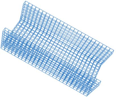
MSGCE 2021                                                                                                     IOP Publishing
IOP Conf. Series: Earth and Environmental Science 768 (2021) 012051                        doi:10.1088/1755-1315/768/1/012051

Finite element analysis of u-shaped reinforced concrete
column

                     Jiuyang Li 1, Xiaoyu Wang 1*, Weinan Ma 2
                     1
                         School of Civil Engineering, Changchun Institute of Technology, Changchun, China
                     2
                         Sinohydro Northeast Survey and Design Research Co., Ltd.
                     *
                         Corresponding author’s e-mail: wxy18339168120@163.com

                     Abstract: Special shaped column is called frame column with special-shaped section. Under
                     the condition of fully considering the strength and stiffness requirements of the whole structure,
                     the U-shaped column is used in the new structural system of contemporary subway
                     architectural pattern, which mainly uses special-shaped column instead of ordinary rectangular
                     column to form the so-called "explicit frame", so as to promote the interaction between steel
                     and concrete, and greatly improve the bearing capacity of components power. In this paper, the
                     bearing capacity, bending deformation and failure mode of U-shaped reinforced concrete
                     column are analyzed through the finite element software ABAQUS under the change of wall
                     thickness and height, which provides a theoretical basis for the future research on the
                     performance of U-shaped reinforced concrete column.

1. Introduction
With the rapid development of social economy, people’s design concept is becoming more and more
novel. The main task of design is to ensure structural safety first, and then create conditions on the
basis of which to improve and develop the architectural function, making the design and use of
subway buildings more flexible and convenient. The rectangular and circular reinforced concrete
column structure are used in China 's subway buildings, which is convenient for construction, but the
bearing capacity is not good. It has these disadvantages, such as self-weight, seismic performance
overall poor and inflexible architectural layout. Multi-storey and high-rise structures have been more
and more widely used in practical engineering, in order to improve the bearing capacity and meet the
requirements of various aspects and ensuring the bearing capacity and ductility of the structure within
the safe range, it is necessary to appropriately increase the cross-section size of the rectangular column,
so that it cannot be met at the same time.
    In reinforced concrete special-shaped columns, the change of section size makes the constraint
effect of internal concrete stronger, which is in a state of symmetric compression, and the bearing
performance is greatly improved. The supporting effect of concrete increases the overall stability of
steel bars and avoids local buckling, the ductility characteristics may also be improved. However,
considering the complex stress of the components in the actual subway project, the research on the
deformation and failure characteristics of reinforced concrete special-shaped columns is limited.
    In order to determine the bearing capacity, bending deformation and failure mode of U-shaped
reinforced concrete columns under certain conditions, the finite element analysis software analyzes the
stress and deformation performance, which provides a basis for experimental research.

              Content from this work may be used under the terms of the Creative Commons Attribution 3.0 licence. Any further distribution
              of this work must maintain attribution to the author(s) and the title of the work, journal citation and DOI.
Published under licence by IOP Publishing Ltd                          1
MSGCE 2021                                                                                IOP Publishing
IOP Conf. Series: Earth and Environmental Science 768 (2021) 012051   doi:10.1088/1755-1315/768/1/012051

2. Abaqus software introduction
Finite element method is a widely used method in engineering simulation and plays a vital role in
different industries and fields. As one of the largest finite element softwares in the world, ABAQUS
can be simulated in a wide range. This software provides a large number of different types of element
models, material models, and analysis processes, which can provide research in different fields for
selection. The most significant advantage of this software is that it can almost solve all simple linear
elastic problems, and can also provide corresponding solutions for some complex nonlinear problems.
When using this software for linear analysis, the calculation efficiency is high. In the calculation
process, the software can automatically select the load increment suitable for the model by analyzing
the characteristics of different models, and adopt reasonable convergence criteria. In the calculation
process, these parameters can be adjusted automatically and continuously in time to facilitate
calculation. Finally, the maximum accurate solution effect is achieved, and the analysis efficiency is
greatly improved. The analysis module of ABAQUS is divided into two parts: ABAQUS / Standard
for static analysis and ABAQUS / Explicit for dynamic analysis. This paper mainly uses static
analysis.

3. Abaqus finite element analysis process

3.1.Working condition of specimen
Finite element specimen size: In order to consider the influence of U-shaped column cantilever wall
thickness and height on the bearing capacity, the parameters of finite element analysis are designed.
U-shaped column cantilever wall thickness is 150mm, 200mm, 250mm; When the cantilever wall
thickness of U-shaped column is 150mm, the height of U-shaped column is 1500mm, 2000mm,
2500mm respectively. A total of two groups of six finite element specimens are designed, and the
calculation parameters are shown in Table 1 and Table 2.

                        Table 1. U-shaped column finite element condition table
    Working       Test specimen Reinforcement       Stirrup            Wall                Height
    condition        number         ratio     reinforcement ratio thickness/mm              /mm
                         1             0.29%             0.58%              150             2500
    group one            2             0.29%             0.58%              200             2500
                         3             0.29%             0.58%              250             2500
                         4             0.29%             0.58%              150             1900
    group two            5             0.29%             0.58%              150             2200
                         6             0.29%             0.58%              150             2500

3.2.Properties and constitutive relations of concrete materials
The U-shaped concrete used in this test is C50 concrete, and the mechanical properties of C50
concrete materials are determined according to Code for design of concrete structures GB50010 -
2010. The mechanical properties of C50 concrete are shown in Table 3. The stress before yield should
yield 360 MPa, which is considered to be in a fully elastic state. The mechanical properties of the steel
bar are shown in Table 4.

                                                     2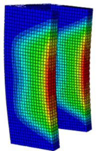
MSGCE 2021 IOP Publishing
IOP Conf. Series: Earth and Environmental Science 768 (2021) 012051 doi:10.1088/1755-1315/768/1/012051
Table 2. Mechanical properties of C50 concrete
Standard value of
Elastic Standard value of
grade of Poisson ratio uniaxial Compression stiffness Recovery factor of
modulus uniaxial tensile
concrete λ compressive recovery factor tensile stiffness
N/mm2 strengthN/mm2
strengthN/mm2
C50 2.69×10⁴ 0.2 1.89 23.1 0.9 0
Table 3. Mechanical property of steel bars
Design tensile Elongation
Elastic modulus Poisson ratio
Steel grade strength percentageN/m
N/mm2 λ
N/mm2 m2
HRB400 360 7.5 2.00×10⁵ 0.25
3.3. Modeling process
The finite element analysis software ABAQUS is used to create the components of U-shaped concrete
column in the ratio of 5: 1 through the component creation (part module. Summarizes the experience
of finite element analysis results, combined with the structural characteristics of reinforced concrete
structure itself, using displacement coordination modeling method to establish the model.
The material properties are defined, and the material properties of each component in U-shaped
concrete are defined through the property module. The definitions of concrete and steel are determined
according to the above material properties and constitutive parameters, respectively.
Component assembly and interaction, the assembly module is used to assemble the various
components of the model orderly, and then assembly positioning is carried out to form the assembly.
Finally, through the interaction module, the through-length reinforcement, stirrup, tie bar and
longitudinal reinforcement are bound into a whole embedded into the whole concrete component. The
assembly of finite element model components is shown in Figure 1.
(a) cage of reinforcement (b) concrete
Figure 1. Finite element components
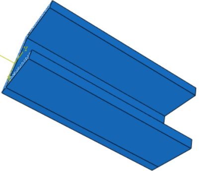
4. Finite element analysis process
Through the finite element software, the deformation of U-shaped reinforced concrete columns under
different working conditions is analyzed. The bending forms of U-shaped columns under vertical load
are shown in Figure 2. According to the working conditions in Table 1 and Table 2, the factors
affecting the deformation of U-shaped columns are compared and analyzed, and the influence of wall
thickness and height of U-shaped columns on the bearing performance of U-shaped reinforced
concrete is obtained.
3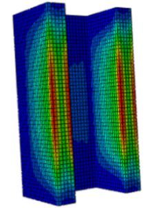
MSGCE 2021                                                                                IOP Publishing
IOP Conf. Series: Earth and Environmental Science 768 (2021) 012051   doi:10.1088/1755-1315/768/1/012051

(a)Wall thickness150mm       (b)Wall thickness200mm      (c) Height 2200mm        (d) Height 2500mm
                                 Figure 2. Condition 2 Bending form

4.1. Influence of wall thickness and height variation on u-shaped reinforced concrete columns

4.1.1. Load capacity of lubricant -carrying properties. Under the finite element calculation model, the
relationship between the bearing capacity and time of the specimen is shown in Figure 3. The analysis
results show that under certain conditions, with the increase of U-shaped concrete column wall
thickness, the maximum bearing capacity of the column increases gradually. With the increase of the
height of U-shaped concrete column, the bearing capacity of the column increases gradually.

                 Figure 3.The relationship between load and time under two conditions

4.1.2. Damage pattern. This model simulates the vertical force along the centroid direction, under
different wall thickness, axial compression deformation and failure characteristics are basically the
same in monotonic loading process, this paper takes the equivalent plastic strain diagram Figure 4 of
concrete and steel bar as an example to reflect the deformation and failure characteristics of the
specimen.

 (a) Concrete deformation diagram and stress cloud (b)Steel bars deformation diagram and stress cloud
                     Figure 4.Component deformation diagram and stress cloud

                                                     4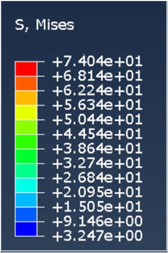
MSGCE 2021                                                                                IOP Publishing
IOP Conf. Series: Earth and Environmental Science 768 (2021) 012051   doi:10.1088/1755-1315/768/1/012051

    From Figure 4, it can be seen that under axial compression, the U-shaped concrete column is in the
middle of the drum failure, and there is no significant change in the upper and lower ends, so the
deformation in the middle of the column is the largest.
    It can be seen from the deformation and stress nephogram of the reinforcement in Figure that the
stress values of the longitudinal reinforcement and the horizontal stirrup in the middle of the column
are the largest, reaching 360 MPa. The stirrup is explicitly red in the figure. The reason why most of
the longitudinal reinforcement in the figure is explicit red is that under the action of axial load, each
longitudinal reinforcement is uniformly loaded. When the load reaches the yield stress of the
reinforcement, the longitudinal reinforcement in the figure is all red. The horizontal stirrup stress at
the upper and lower ends of the specimen is small. It can be seen from the deformation diagram that
the specimen has an outward protruding deformation in the middle of the column, and the horizontal
stirrup has a transverse deformation.
    It is not difficult to see from the deformation and stress nephogram of concrete in Figure 4 that
under the action of axial load, the axial force gradually transfers from the upper part of the column to
the middle part of the column. At this time, the concrete stress in the middle part of the column begins
to gradually increase. When the ultimate compressive strain of concrete is reached, the concrete stress
in the middle part of the column shows a downward trend. Therefore, in the stress nephogram of
external concrete, the stress in the middle part of the column is the smallest, which is explicitly shown
as the blue area in the figure.

5. Conclusions
(1) In this paper, the axial compression of U-shaped reinforced concrete columns is simulated and
analyzed by using the finite element analysis software ABAQUS, and the stress-strain curves of the
compression components are obtained. The mechanical properties and deformation characteristics of
U-shaped concrete columns under two working conditions are compared. It is concluded that under the
same other conditions, with the increase of height and wall thickness, the bearing capacity of
U-shaped concrete columns has been significantly improved, and the ductility performance has also
been significantly improved, showing the outstanding contribution of height and wall thickness to the
bearing capacity and deformation capacity of components.
    (2) In this paper, the failure characteristics and stress of the components are simulated according to
the subway building. The failure mode of the whole U-shaped reinforced concrete column under the
axial load is that the concrete is crushed, and the longitudinal reinforcement between the stirrups is
lateral bulged. The failure mode of the whole column is that the middle bulge is moon-shaped. After
the upper and lower ends are stressed, the force is effectively transferred from the upper and lower
ends to the middle part. The load is concentrated in the middle position of the column, so the upper
and lower parts are less damaged, and the middle part is moon-shaped.
    (3) In this paper, the deformation curves of concrete and steel bar in the loading process are
compared. Before the ultimate bearing capacity, the steel bar and concrete maintain a good synergy.
When the specimen reaches the ultimate load, the steel bar plays a very important role in improving
the ductility of the component.

References
[1] Rong,B., Chen, Z.H., and Zhou ,T. (2009) Research on axial compression strength of l-shaped
         shopt column composed of concrete-filled square steel tubes.,39:04-107.
[2] Rong,B., Chen, Z.H., (2009) Research on axial compression stability of L-shaped column
         composed of concrete-filled square steel tubes.,39:39-42.
[3] Li,K.W., Zhou, Y. (2012) Mechanical Properties Analysis of Steel Reinforced Concrete Column
         Based on ABAQUS, J.SiChuanJianZhuKeXueYanJiu.,38:67-69.
[4] Guo,Y.F. (2017) Seismic Performance Analysis for T Column with Concrete Filled Steel Tube
         Basing on ABAQUS.

                                                     5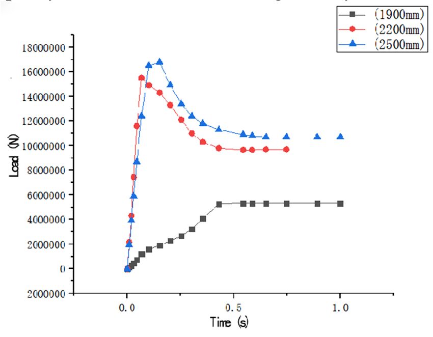
MSGCE 2021                                                                                IOP Publishing
IOP Conf. Series: Earth and Environmental Science 768 (2021) 012051   doi:10.1088/1755-1315/768/1/012051

[5] Zhou,J. (2017) Finite element analysis of steel reinforced concrete columns based on
         ABAQUS,J.Guangdong Building Materials.,33:49-53.
[6] Ling,Y.M., Hang,L., Zhang,H.B., Xu,W.K., and Xu,Y.F. (2019) Finite element analysis of axial
         compression performance of L-shaped steel reinforced recycled concrete special-shaped
         columns.
[7] Zhou,Y.Y., Xiao,Y.M. (2020) Finite Element Analysis of Rear Steel Tube Reinforced Concrete
         Column Based on ABAQUS,J.Anhui Building Materials,27:77-79.
[8] GB50010-2010, design code for concrete structure[S].

                                                     6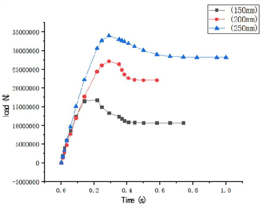
You can also read