Effects of nano-modified polymer cement-based materials on the bending behavior of repaired concrete beams
←
→
Page content transcription
If your browser does not render page correctly, please read the page content below
Nanotechnology Reviews 2021; 10: 292–303
Research Article
Tao Meng*, Songsong Lian, Xiufen Yang, and Ruitan Meng
Effects of nano-modified polymer cement-based
materials on the bending behavior of repaired
concrete beams
https://doi.org/10.1515/ntrev-2021-0024 structural components with polymer-modified cement-
received March 27, 2021; accepted April 10, 2021 based materials.
Abstract: As the use time of concrete structures increases, Keywords: nano-modified polymer, repaired concrete beam,
defects such as concrete cracks, corrosion and exposure bending behavior
of steel bars gradually appear, resulting in additional
repair of concrete structures to increase their durability
and life. In this article, the effects of nano-modified
polymer cement-based materials as repair material on 1 Introduction
the bending behavior of repaired concrete beams were
studied. Based on the moment, deflection, strain, surface Concrete is widely used as the main material in various
quality and cracking development monitor of repaired construction projects including houses, bridges, tunnels
concrete beams, the bending behavior of repaired beams and other structures. As the use time of concrete struc-
with polymer, nano-modified polymer and fibers was tures increases, defects such as concrete cracks, corro-
compared and the failure mechanism of the beams was sion and exposure of steel bars gradually appear, which
analyzed. The results showed that the nano-modified affect the safety of the structure. Thus, old buildings
polymer cement-based materials are helpful in improving have started demanding additional repair and rehabilita-
the performance of repaired beams, manifested by the tion to increase their durability and life. For reinforced
increase in the ultimate bending moment and the signifi- concrete beams, cracks appear in the tension area of con-
cant improvement in the quality of the interface between crete beams during the service process of the beam
repair and matrix concrete. Compared with polymer cement- due to the low tensile strength of concrete. With time,
based materials, nano-modified polymer cement-based mate- these cracks lead to the corrosion of reinforcement, and
rials result in a 27% increase in ultimate bending moment the corrosion of steel bars can lead to concentration of
of the repaired beam and a 58% increase in cracking internal stresses in the concrete and reduction in bond,
moment, while reducing the total number of cracks by resulting in further cracking and deterioration [1]. There-
23% and the average width of cracks by 17% in the fore, it is necessary to study the new repair materials for
repaired beam. This article demonstrated the availability the rehabilitation of reinforced concrete beams.
of nanomaterials for improving the loading behavior of A good repair improves the function and perfor-
mance of the structure, restores and increases its strength
and stiffness, enhances the appearance of the concrete
surface, provides water tightness, prevents ingress of
* Corresponding author: Tao Meng, College of Civil Engineering and the aggressive species to the concrete/steel interface
Architecture, Zhejiang University, Hangzhou, China,
and improves its durability [2]. Commonly used repair
e-mail: taomeng@zju.edu.cn
Songsong Lian: College of Civil Engineering and Architecture, materials include cement, epoxy resins, polyester resins,
Zhejiang University, Hangzhou, China, polymer latex, etc. [3]. Polymer cement-based materials
e-mail: 11712050@zju.edu.cn are widely used among the repair materials, which consist
Xiufen Yang: College of Civil Engineering and Architecture, Zhejiang of a conventional cement mortar incorporating polymer
University, Hangzhou, China, e-mail: 1660761671@qq.com
latex [4].
Ruitan Meng: College of Civil Engineering and Architecture,
Zhejiang University, Hangzhou, China; Architectural Design and
Polymer cement-based materials attracted the atten-
Research Institute of Zhejiang University, Hangzhou, China, tion of academia after a patent for adding natural rubber
e-mail: mrt207@126.com latex to road construction materials was obtained by
Open Access. © 2021 Tao Meng et al., published by De Gruyter. This work is licensed under the Creative Commons Attribution 4.0
International License.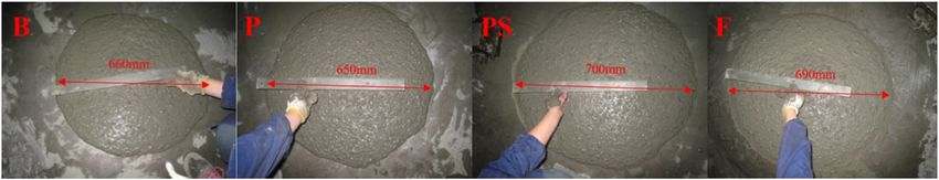
Effects of nano-modified polymer cement-based materials on repaired concrete beams 293
Cresson in 1923 [5]. Polymer cement-based materials It shows that nanomaterials are effective in modifying
became popular as a construction material during the polymer cement-based materials.
1950s and was used to repair damaged concrete structures Based on the above background, it is found that the
during the 1980s [6,7]. At present, polymer cement-based polymer materials are a widely used repair material.
materials are being used in the repair and reinforcement Nanomaterials have great potential to modify polymer
of many projects such as hydraulic engineering, harbor cement-based materials, and there are currently few stu-
engineering, highways, bridges and residential build- dies about it. Thus, as a new potential repair material, the
ings. At the same time, some scholars have carried out actual repair effect of nano-modified polymer cement-based
related research on the application of polymers in repaired materials on concrete structure needs further verification.
concrete. Pellegrino and Modena [8] used polymer-modi- Meanwhile, it is found that the polymer cement-based
fied mortar to repair different areas of reinforced concrete materials were used in the form of bonding directly in
beams and found that repairing the concrete compression the existing research. In particular, there is no research
area can improve the bending resistance of reinforced to simulate the repair process of removing the old concrete
concrete beams; Assaad [9] applied polymers to repair and filling it with repair materials. Considering partial or
projects and found that latex powder effectively improved total removal and replacement of concrete is unavoidable
the workability and bending behavior of cement-based for severely damaged concrete, it is necessary to simulate
materials. Mirza et al. [10] evaluated the performance the replacement of concrete with repair materials and
of polymer-modified cement-based mortars for repairing investigate the performance of the concrete structure after
surfaces of concrete structures up to a depth of 75 mm repairing.
damaged due to exposure to cold climates. Polymer Therefore, the objective of this article is to verify the
cement-based materials are widely used as repair mate- technical performance of nano-modified polymer cement-
rial due to their good tensile resistance and strong adhe- based materials as repair materials in the structural com-
sive force [11,12] and are beneficial in improving the inter- ponents and promote their wide application in the field
face of cement-based materials [13–15]. of reinstatement construction. At the same time, this
Moreover, many scholars have conducted related article simulates the real repair process after concrete
research on the modification of the polymer cement-based damage in the tension zone of the beam and studies the
materials [16–20]. Fibers are often used to composite with technical performance of the repaired concrete beam,
polymer to improve the performance of cement-based which has far-reaching reference value for actual engi-
materials. Xu et al. [19] demonstrated the compound neering. Specifically, the effects of polymer, nano-modi-
effects of polyester fiber and SBR latex on the mechanical fied polymer and fibers on the bending behavior of
properties of concrete and found that polyester fiber rein- repaired concrete beams were compared and the failure
forced the modification effects of the SBR latex, whereas mechanism of the beams was analyzed based on the
the promotion of polyester fiber on the mechanical pro- moment, deflection, strain, surface quality and cracking
perties was also built up with the addition of the SBR development monitor of repaired concrete beams.
latex. In addition to fibers, nanomaterials are also com-
monly used in the compounding and modification of
materials, which show a series of excellent physical
and chemical properties due to the small size effect, sur-
face effect and macroscopic quantum tunneling effect
2 Experiment
[21]. Over the past few decades, researchers have made
much progress by using nanomaterials to improve tech- 2.1 Materials
nical properties of cement-based materials [22–26]. The
results showed that the mechanical properties and micro- P.O 42.5 cement produced by Anhui Conch Cement
structure of the interface transition zone of cement-based Company, sand of China’s ISO standard produced by
materials were modified by nanomaterials due to their Xiamen Iso Sand Company, polycarboxylate superplasti-
positive effect on the hydration process and pore structure cizer with a water-reducing rate of 32% produced by
[27–36]. Besides, Meng et al. [37] found that Nano-SiO2 is Suzhou Xinlong Chemical Building Materials Company
helpful in improving the compressive strength and flex- and defoamer (AGITANP803) produced by Germany MÜNZING
ural strength of polymer cement-based materials in the Company were used. VK-S01B nano-SiO2 dispersion was
early age due to the increase in hydration rate of cement. produced by Hangzhou Wanjing New Materials Company.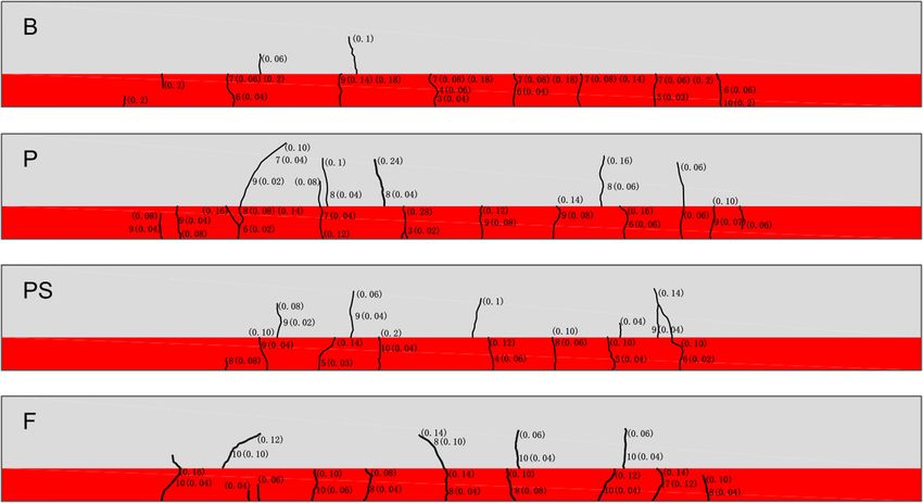
294 Tao Meng et al.
Table 1: Chemical composition of cement velocity of the repair layer, crack development, as well as
the failure load and ultimate load of the beam.
Composition SiO2 Al2O3 Fe3O4 CaO MgO SO3 Na2O
wt% 22.37 4.36 3.38 61.08 2.43 2.45 0.506
2.2.1 Preparation of beams
Polymer powder produced by Germany Wacker Chemie The dimensions and reinforcement of the reinforced con-
AG was made up of ethylene vinyl acetate (EVA) copo- crete beam are shown in Figure 2. The control concrete
lymer. The fiber material used in the test was poly- was poured first, which had a mix proportion of 360 kg
propylene (pp) fiber produced by Shanghai Yingjia cement, 1,116 kg gravel, 744 kg sand, 180 kg water and
Industrial Development Company. The chemical compo- 3.6 kg polycarboxylate superplasticizer per cubic meter
sition of cement is shown in Tables 1–4 show the main of concrete. After curing for 2 weeks, the repair materials
properties of nano-SiO2, polymer and fiber, respectively. made of self-compacting fine stone concrete with dif-
The information in Tables 1–4 was provided by the ferent proportions were casted into the lower part of the
manufacturers. beams. The mix proportion of repair materials is shown in
Table 5. The test beams were cured under the condition of
temperature 20°C and humidity 55%.
2.2 Experiment method
2.2.2 Fluidity and compressive strength of concrete
By testing the performance of reinforced concrete beams
repaired by different materials, the effects of polymer, The slump and T50 of concrete were measured according
nano-modified polymer and fibers on the bending beha- to “Technical Specification for Application of Self-com-
vior of the beams were evaluated and compared. The test pacting Concrete” (JGJ/T283-2012) [38]. By adjusting the
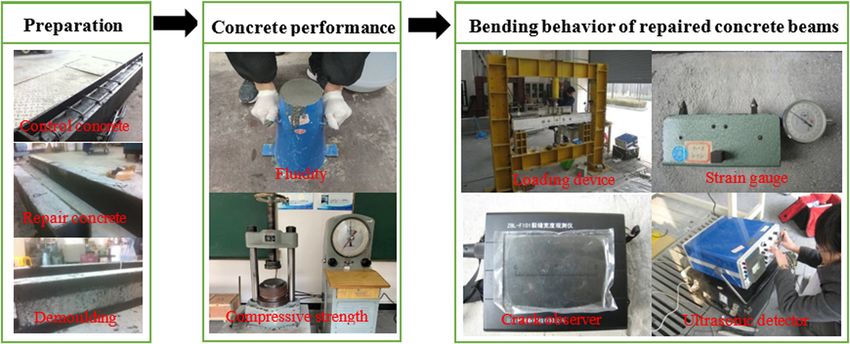
process is shown in Figure 1. The fluidity and mechanical amount of superplasticizer, the fluidity of the concrete was
properties of concrete were tested and the bending beha- guaranteed to be basically the same, as shown in Figure 3.
vior of the beam was evaluated by the displacement at Samples with a size of 100 mm × 100 mm × 100 mm were
the supports and mid-span under various loads, tensile prepared for the compressive strength test. According to
strain in the middle of the steel bar and compressive “standard for test methods of mechanical properties on
strain at the compressive edge of the concrete, ultrasonic ordinary concrete” (GB/T50081-2019) [39], the compressive
Table 2: Physical and chemical properties of nano-SiO2
Outward Solvent Average diameter (nm) SiO2 (%) pH Na2O (%)
Translucent liquid Water 13 30.1 10.2 0.32
Table 3: Technical indicators of polymer powder made up of ethylene vinyl acetate copolymer
Solid content (%) Apparent density (g/L) Particle size (μm) Minimum film forming temperature (°C)
99 540 0.5–8 4
Table 4: Technical indicators of pp fiber
Density (g/cm3) Length (mm) Diameter (µm) Elongation at break (%) Elastic modulus (GPa) Tensile strength (MPa)
0.91 19 20 30 4.5 400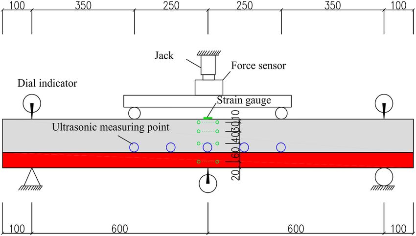
Effects of nano-modified polymer cement-based materials on repaired concrete beams 295
Figure 1: Test process.
strength of concrete samples was measured in triplicates load and cracking load of the experimental beam were
at 14 days and 28 days of curing with a loading rate of calculated. From equations (1) and (2), the ultimate
0.5 MPa/s. bending moment can be calculated to be 4.84 kN m.
From equations (3) to (5), the cracking moment can be
calculated to be 1.57 kN m .
2.2.3 Bending behavior of reinforced concrete beam α1 fck bx = fyk As , (1)
Mu = α1 fck bx h0 − ,
The bending behavior tests of the repaired beam were x
(2)
carried out when the repaired layer concrete was cured 2
to the age of 14 days. The instruments and equipment where fck and fyk , respectively, represent the axial com-
used in the test included TS3860 strain gauge, force pressive strength of concrete and the strength of steel
sensor, dial indicator, extensometer with 10 cm gauge bar; As represents the cross-sectional area of the steel
length, jack, crack observer and ultrasonic detector, etc. bar in the tension zone; x represents the height of the
The loading device and instrument layout of the test concrete compression zone; b represents the width of
beam are shown in Figure 4. the cross section; h0 represents the effective height of
According to “Code for Design of Concrete Structures” the cross section; and Mu represents the ultimate bending
GB 50010-2010 [40], the ultimate load, normal service moment.
I0 = (0.083 + 0.19αE ρ) bh3 , (3)
y0 = (0.5 + 0.425αE ρ) h , (4)
γm ftk I0
Mcr = , (5)
h − y0
where I0 represents the moment of inertia; αE represents
the ratio of the elastic modulus of steel bar to that of con-
crete; ρ represents the longitudinal reinforcement ratio; γm
represents the influencing coefficient of section resistance
to plasticity; ftk represents the axial tensile strength of
concrete; and Mcr represents the cracking moment.
The experimental beams were loaded in stages with
about 10% of the calculated ultimate load. When the load
reached 90% of the calculated cracking load, the load
was changed to 5% of the calculated ultimate load until
Figure 2: Dimensions and reinforcement of the reinforced the first crack appeared on the experimental beam. After
concrete beam. exceeding the normal service load, the beam was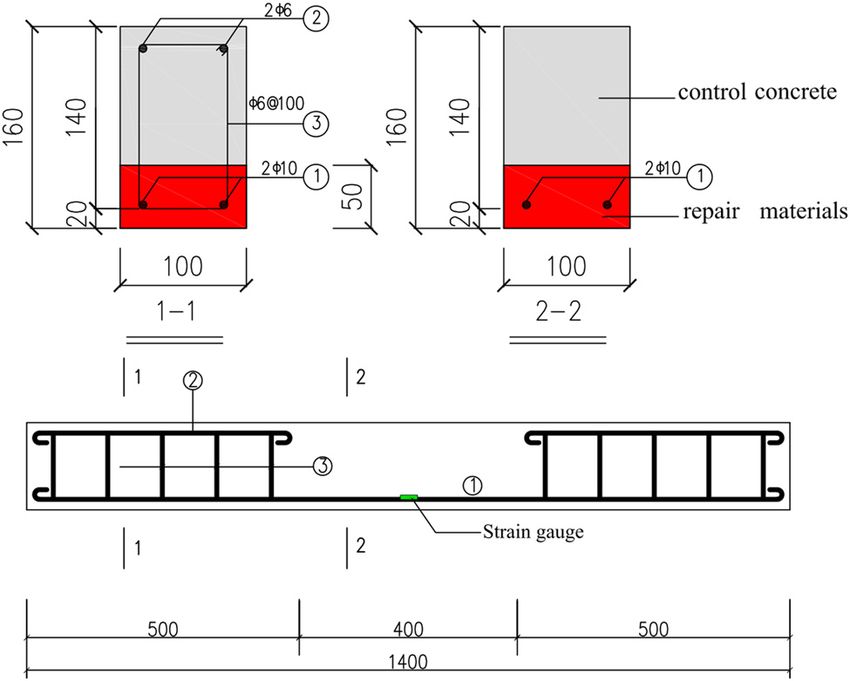
296 Tao Meng et al.
Table 5: Mix proportion of self-compacting fine stone concrete (kg/m3)
Sample Cement Gravel Sand Water Superplasticizer Nano-SiO2 EVA Defoamer Polypropylene fiber
B 512 848 781 205 3.58 — — — —
P 512 848 781 205 1.24 — 25.6 0.51 —
PS 512 848 781 205 5.12 5.12 25.6 0.51 —
F 512 848 781 205 3.58 — — — 0.9
Figure 3: Spreading of fresh concrete.
continued to load at 10% of the calculated ultimate load. crack distribution and maximum crack width; and (5)
Finally, when it reached 90% of the ultimate load, the ultimate bending moment and ultimate compressive
beam was continued to load until it reached the ultimate strain of concrete.
bearing state. According to this classification method, the
load was divided into 11 levels. After the eleventh level of
load, the beam was loaded to failure and the load at this
time was the twelfth level. During the loading process,
3 Results and discussion
the measured data mainly include (1) the displacement
of the support and the mid-span under various loads; 3.1 Compressive strength
(2) tensile strain at the middle of the main bar and
compressive strain at the edge of the concrete under The compressive strength of the control concrete at the
various loads; (3) ultrasonic velocity of repair layer under age of 14 days was 40.3 MPa. The compressive strengths
various loads; (4) the cracking moment of the beam and of the repair materials at 14 and 28 days are shown in
the development of cracks under various loads, including Figure 5.
Figure 4: Illustrative diagram of beam bending behavior test of repaired beam.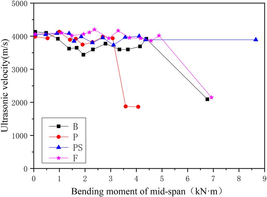
Effects of nano-modified polymer cement-based materials on repaired concrete beams 297
60 Table 6: Cracking load and ultimate bearing capacity of reinforced
B concrete beams
P
50 PS
Cracking moment (kN m)
Compressive Strength(MPa)
F Sample Ultimate bending
40
moment (kN m)
Value Load level Value Load level
30
B 6.77 12 0.94–1.38 3
P 6.82 12 0.99–1.41 3
20 PS 8.66 12 1.57–1.85 4
F 6.93 12 2.17–2.37 5
10
0 the bonding surface changed the distribution and trans-
14d 28d
mission of the force in the beam, resulting in the repair
Age layer sharing more tension and cracking more easily.
Figure 5: Compressive strength of repair materials. The cracking moment of PS was 58% larger than that
of P. This was because nanomaterials not only had a
good effect in improving material properties and interface
When the concrete beam was loaded, the repair bonding but also promoted the formation of polymer film
materials had been cured for 14 days and the control in concrete, improving the bending and cracking resis-
concretes had been cured for 28 days. The results showed tance. The cracking moment of F was 38% larger than
that the compressive strength of the repair materials at that of PS, indicating that the pp fiber had the most
the age of 14 days and that of the control concretes at the obvious effect in improving the cracking resistance of
age of 28 days were approximately the same. Upon com- the repaired beam. This was because the fibers were dis-
paring the strength development of the repair materials, tributed in random directions in the concrete, which dis-
it could be found that the compressive strength of the persed the shrinkage stress and energy of the concrete to
four repair materials at the age of 14 days was relatively the fibers and weakened the plastic shrinkage stress
close. The compressive strength of the specimen PS at the effectively, thereby reducing the stress concentration at
age of 28 days was significantly higher than that of the the crack tip and preventing the further expansion of the
other three specimens, indicating that the nanomaterials crack.
had an obvious effect in improving the compressive The theoretical calculation value of the ultimate
strength of concrete. Meanwhile, the compressive strength bending moment was 4.84 N m. The ultimate bending
of specimens P and F was slightly higher than that of moments of B, P, PS and F were 40, 41, 79 and 43% higher
specimen B, indicating that the polymer and pp fiber than the theoretical value. It can basically be determined
played a beneficial role in the compressive strength of that the actual strength of the tensile steel was higher
concrete. than the design value, which made the experimental
value higher than the theoretical value. Among them,
the ultimate bending moment of the PS was the largest,
3.2 Cracking load and ultimate bearing which was 28% larger than that of B, 27% larger than that
capacity of P and 25% larger than that of F, indicating that the
nanomaterials can modify the polymer cement-based
The repaired beams were loaded in stages and the crack- materials and greatly improve the bending resistance of
ing load and ultimate bearing capacity were measured, the repair beam.
respectively, as shown in Table 6.
The bending moment when the first crack appeared
was taken as the cracking moment. The theoretical cal- 3.3 Deflection
culation value of the cracking moment was 1.58 kN m.
The cracking moments of B and P were smaller than the Figure 6 shows the relationship between the deflection of
theoretical value. This was because the repair layer of the the repaired beam and the mid-span bending moment. It
beam cannot be well integrated with the control layer and can be seen that when the load was small (before the298 Tao Meng et al.
9
8 B
Bending moment of mid-span(M/KN·m)
P
7 PS
F
Bending moment /(KN·m)
6
5
4
3
2
1
0
0 1 2 3 4 5 6 7
Deflection/(mm)
Figure 6: Relationship between the deflection and the bending Tensile strain of the main bar (εs /10-6)
moment of mid-span.
Figure 7: Tensile strain of the main bar in bending under various
loads.
eighth load), the deflection of F was the smallest, while
the deflection of other groups was not much different,
indicating that the fiber materials were beneficial to con-
trolling the deflection and deformation of the beam.
Bending moment of mid-span(M/KN·m)
When the mid-span bending moment was greater than
5 kN m, the deflection of PS was smaller than the other
three groups, indicating that the nano-modified polymer
cement-based materials can not only increase the strength
of the repaired beam but also increase the rigidity. This
was because the addition of nanomaterials has a benefi-
cial effect on the formation of the polymer film and the
properties of the bonding surface.
3.4 Strain development of concrete and
steel
Compressive strain of the upper concrete(εs /10-6)
Figure 7 shows the tensile strain values of the main bars
Figure 8: Compressive strain of the upper concrete under various
in the bending of different beams under various loads.
loads.
Figure 8 shows the compressive strain values of different
beams at the center of the upper concrete under various
loads. It can be seen that the compressive strain of the effectively be distributed and transmitted on the bonding
concrete and the tensile strain of the steel bars had linear surface.
relationships with the bending moments, indicating that Figure 9 shows the strain at mid-span section of the
the compression zone of concrete and steel bars had not concrete beam under different load levels before the
reached the yielding state from the beginning of loading beam fails. It can be seen that there was no linear rela-
to the beam failure. Therefore, the final failure of beams tionship between the concrete strain of the beam and its
was not caused by the yield of steel bars or the failure of corresponding height. This was because the bonding sur-
concrete, but mainly depended on the performance of the face of the control layer and the repair layer of the rein-
bonding surface. In other words, it was very important forced concrete beam changed the force distribution and
whether the force in the reinforced concrete beam can transmission, where the assumption that the section isEffects of nano-modified polymer cement-based materials on repaired concrete beams 299
160 160
120 120
h(mm)
h(mm)
80 80
40 40
-0.5 0.0 0.5 1.0 1.5 -0.5 0.0 0.5 1.0 1.5
-6 -6
(a) ε(10 ) (b) ε(10 )
160 160
120 120
h(mm)
h(mm)
80 80
40 40
-0.5 0.0 0.5 1.0 1.5 -0.5 0.0 0.5 1.0 1.5
-6 -6
(c) ε(10 ) (d) ε(10 )
Figure 9: Strain at mid-span section of the concrete beam under different load levels before the beam fails. (a) B, (b) P, (c) PS, and (d) F.
plane was not satisfied. Among them, the relationship after the load of each level was stabilized and five mea-
between the strain and its corresponding height of the suring points were tested, as shown in Figure 4. The
concrete in group PS was the closest to linear, indicating results found that only the mid-span had a large change
that the use of nano-modified polymer cement-based in ultrasonic velocity. Figure 10 shows the relationship
materials can improve the integrity of the beam and the between the ultrasonic velocity and the bending moment
performance of the bonding surface. of mid-span. When the ultrasonic velocity was signifi-
cantly reduced, it was determined that the bonding sur-
face had slipped or separated.
As shown in the figure, the ultrasonic velocity of mid-
3.5 Bonding quality of interfacial surface span of different beams fluctuated around 3,500–4,000 m/s
before the bonding surface was separated. The ultrasonic
The ultrasonic velocity of mid-span was used to charac- velocities of B and F did not change significantly before
terize the bonding quality between the repair layer and the twelfth level loading. When the beams were loaded to
the control layer. The ultrasonic velocity was recorded failure, the ultrasonic velocities were found to reduce to300 Tao Meng et al.
time and the number outside the parenthesis represents
the loading level when the crack occurs. The second mark
shows the position of the crack reached at the last
loading level before the beam failure and the maximum
width of the crack at this time. Table 7 summarizes the
number, maximum width and average width of cracks in
the concrete beams.
For group B, the cracks developed mainly from the
bottom of the concrete to the bonding surface, and the
width of the cracks was relatively thick. The distribution
of cracks presented the characteristics of more cracks in
the lower part of the concrete and less in the upper part.
For group P, the number of cracks was the largest and the
distribution was the widest compared with the other
Figure 10: Relationship between bending moment of mid-span and groups. Moreover, in addition to cracks extending from
ultrasonic velocity. the bottom of the concrete to the bonding surface, mul-
tiple cracks developed from the bonding surface to the
upper part of the concrete. For group PS, there were
2,092 and 2,146 m/s, respectively, indicating that the
cracks that developed upward from the bottom of the
bonding surface of B and F was separated at this time.
concrete and upward from the bonding surface. The total
When the beam of P was loaded to the ninth level, where
number of cracks in group PS was 23% less than that in
the bending moment was 3.6 kN m, the ultrasonic velo-
group P, and the average crack width in group PS was
city suddenly reduced to 1,876 m/s with the waveform
17% smaller than that in group P, indicating that the
reversed, indicating that the bonding surface had begun
addition of nanomaterials can effectively control the
to separate before the beam was damaged. The ultrasonic
development of cracks. At the same time, the upper and
velocity of PS was maintained between 4,166 and
lower parts of the cracks in group B developed separately
3,846 m/s from the beginning of loading to failure, indi-
and rarely penetrated, which indicated that a certain
cating that the bonding surface was always well bonded
amount of slip occurred at the bonding surface and the
when the repaired beam was damaged. It can be seen that
shear force could not be transmitted. The beam of group
the nano-modified polymer cement-based materials can
PS had cracks penetrating up and down, indicating that
not only increase the ultimate bearing capacity of the
the interface has good bonding performance and can
repaired beams but also enhance the bonding surface,
transmit shear force. This further proved that the nano-
making the interface between the new and the old con-
modified polymer cement-based materials can enhance
crete well bonded.
the properties of the bonding surface.
According to the test results of bonding surface and
deflection, the performance of bonding surface played
an important role in the control of deflection. We found
that the nano-modified polymer cement-based materials
3.7 Failure mechanism
had a very good effect in improving the bonding force
of the interface between the new and the old concrete,
According to the analysis of cracking moment, ultimate
promoting the deformation well controlled under a
bending moment, deflection, tensile strain of steel bar,
large load.
compressive strain of concrete, bonding surface and cracks,
the failure process and failure mechanism of beams with
different repair materials can be revealed.
3.6 Failure characteristics and crack The cracking and ultimate bending moments of F
morphology were higher than those of B, while the failure character-
istics of B and F were similar. The steel bars and concrete
Figure 11 shows the development of cracks in the repaired of B and F did not yield. The bonding surface detached
beam. There are generally two marks next to a crack. when the beams failed. The distribution of cracks pre-
The first mark shows the position where the crack first sented the characteristics of more cracks in the lower
appeared and the maximum width of the crack at this part of the concrete and less in the upper part.Effects of nano-modified polymer cement-based materials on repaired concrete beams 301
Figure 11: Development of cracks in the repaired beams.
Therefore, the failure mechanism of B and F was that the top of the beam. Therefore, the failure mechanism
the separation of the bonding surface of the repaired of P was that the separation of the bonding surface of
beam caused the unbalanced force distribution inside the repaired beam caused control layer to crack.
the beam. The beam of PS had the largest cracking load and
The cracking load and ultimate bearing capacity of P ultimate bearing capacity. The steel bar and concrete
had a certain increase compared with B. The steel bar and had not reached yield, and the bonding surface had not
concrete had not reached yield. The bonding surface was separated. The respective developed cracks appeared on
partially separated under the ninth level of load and the upper and lower parts of the beam, indicating that the
further expanded with the load. The number of cracks bonding surface may be misaligned.
was the largest and the distribution was the widest.
Taking into account that the tensile steel bars were
located on the repair layer, the lower part of the control
layer was subjected to the tensile force that should be 4 Conclusion
borne by the steel bars after the bonding surface was
partially separated, so that the cracks that developed The overall performance of the repaired reinforced con-
upward from the bonding surface finally penetrated to crete beam was related to the strength and toughness of
Table 7: Summary of cracks in concrete beams
Sample Cracks in the lower part Cracks in the upper part Total cracks
Number Maximum Average Number Maximum Average Number Maximum Average
width width width width width width
B 9 0.20 0.19 2 0.1 0.08 11 0.20 0.17
P 11 0.28 0.12 6 0.24 0.12 17 0.28 0.12
PS 8 0.20 0.11 5 0.14 0.08 13 0.20 0.10
F 10 0.16 0.10 4 0.14 0.10 14 0.16 0.10302 Tao Meng et al.
the repair material and the performance of the bonding Author contributions: All authors have accepted respon-
surface. In this article, the effects of nano-modified polymer sibility for the entire content of this manuscript and
cement-based materials on the bending behavior of approved its submission.
repaired concrete beams are mainly studied. Based on
cracking moment, ultimate bending moment, deflection, Conflict of interest: The authors state no conflict of
tensile strain of steel bar, compressive strain of concrete, interest.
bonding surface and cracks, the bending behavior of con-
crete beams with different repair materials was compared
and the failure mechanism of the beams was analyzed. The
test results were as follows: References
(1) The addition of polymer can slightly increase the
cracking moment and ultimate bending moment of [1] Venkiteela G, Klein M, Najm H, Balaguru PN. Evaluation of the
the repaired beam, but cannot effectively improve compatibility of repair materials for concrete structures. Int J
the performance of the bonding surface, resulting in Concr Struct Mater. 2017;11(3):435–45. doi: 10.1007/s40069-
017-0208-5.
more cracks around the bonding surface.
[2] Al-Zahrani MM, Maslehuddin M, Al-Dulaijan SU, Ibrahim M.
(2) The nano-modified polymer cement-based materials Mechanical properties and durability characteristics of
are helpful in improving the performance of repaired polymer-and cement-based repair materials. Cem Concr
beams, manifested by the increase in the ultimate Comp. 2003;25(4–5):527–37. doi: 10.1016/S0958-9465(02)
bending moment and the significant improvement 00092-6.
[3] Sánchez M, Faria P, Ferrara L, Horszczaruk E, Jonker HM,
in the quality of the interface between repair and
Kwiecień A, et al. External treatments for the preventive repair
matrix concrete. Compared with polymer cement-
of existing constructions: a review. Constr Build Mater.
based materials, nano-modified polymer cement-based 2018;193:435–52. doi: 10.1016/j.conbuildmat.2018.10.173.
materials result in a 27% increase in ultimate bending [4] Huseien GF, Mirza J, Ismail M, Ghoshal SK, Hussein AA.
moment of the repaired beam and a 58% increase in Geopolymer mortars as sustainable repair material: a com-
cracking moment, while reducing the total number of prehensive review. Renew Sust Energ Rev. 2017;80:54–74.
doi: 10.1016/j.rser.2017.05.076.
cracks by 23% and the average width of cracks by 17%
[5] Cresson L. Improved manufacture of rubber road-facing,
in the repaired beam. rubber-flooring, rubber-tiling or other rubber-lining. Br Patent.
(3) The addition of pp fiber can greatly increase the 1923;191(474):12.
cracking load of the repaired beam and slightly increase [6] Akinyemi BA, Omoniyi TE. Engineering properties of acrylic
the ultimate bearing capacity, as well as play a positive emulsion polymer modified bamboo reinforced cement
bonded composites. Eng Struct Tech. 2017;9(3):126–32.
role in the deformation control of the repaired beam.
doi: 10.3846/2029882X.2017.1371085.
Compared with nano-modified polymer cement-based
[7] Jamshidi M, Pakravan HR, Pourkhorshidi AR. Application of
materials, the cement-based material with pp fiber polymer admixtures to modify concrete properties: effects of
increased the cracking moment of the repaired beam polymer type and content. Asian J Civ Eng. 2014;15(5):779–87.
by 38%, significantly improving the cracking resistance [8] Pellegrino C, Modena C. Fiber reinforced polymer shear
of the repaired beam. strengthening of reinforced concrete beams with transverse
steel reinforcement. J Compos Constr. 2002;6(2):104–11.
doi: 10.1061/(ASCE)1090-0268(2002)6:2(104).
In summary, the synergy of nano-SiO2 and polymer [9] Assaad JJ. Development and use of polymer-modified cement
can effectively improve the technical performance of the for adhesive and repair applications. Constr Build Mater.
repaired concrete beam. Nano-modified polymer cement- 2018;163(FEB 28):139–48. doi: 10.1016/
based materials are helpful in improving the ultimate j.conbuildmat.2017.12.103.
[10] Mirza J, Mirza MS, Lapointe R. Laboratory and field perfor-
bending moment and cracking moment of the repaired
mance of polymer-modified cement-based repair mortars in
beam and enhancing the performance of the bonding
cold climates. Constr Build Mater. 2002;16(6):365–74.
surface, thus reflecting a good repair effect. This article doi: 10.1016/S0950-0618(02)00027-2.
demonstrated the availability of nanomaterials for improving [11] Fowler DW. Polymers in concrete: a vision for the 21st century.
the loading behavior of structural components with polymer- Cem Concr Comp. 1999;21(5–6):449–52. doi: 10.1016/S0958-
modified cement-based materials. 9465(99)00032-3.
[12] Kardon JB. Polymer-modified concrete: review. J Mater Civil
Eng. 1997;9(2):85–92. doi: 10.1061/(ASCE)0899-
Funding information: The authors thank the support pro- 1561(1997)9:2(85).
vided by the National Natural Science Foundation of [13] Jafari K, Tabatabaeian M, Joshaghani A, Ozbakkaloglu T.
China (52078453). Optimizing the mixture design of polymer concrete: anEffects of nano-modified polymer cement-based materials on repaired concrete beams 303
experimental investigation. Constr Build Mater. 2018; [26] Ling YF, Zhang P, Wang J, Taylor P, Hu SW. Effects of nano-
167(APR 10):185–96. doi: 10.1016/j.conbuildmat.2018.01.191. particles on engineering performance of cementitious com-
[14] Shehata N, Sayed ET, Abdelkareem MA. Recent progress in posites reinforced with PVA fibers. Nanotechnol Rev.
environmentally friendly geopolymers: a review. Sci Total 2020;9(1):504–14. doi: 10.1515/ntrev-2020-0038.
Environ. 2020;762(5):143166. doi: 10.1016/ [27] Ltifi M, Guefrech A, Mounanga P, Khelidj A. Experimental study
j.scitotenv.2020.143166. of the effect of addition of nano-silica on the behaviour of
[15] Kim JH, Robertson RE, Naaman AE. Structure and properties of cement mortars. Procedia Eng. 2011;10:900–5. doi: 10.1016/
poly (vinyl alcohol)-modified mortar and concrete. Cem Concr j.proeng.2011.04.148.
Res. 1999;29(3):407–15. doi: 10.1016/S0008-8846(98) [28] Kafi MA, Sadeghi-Nik A, Bahari A, Sadeghi-Nik A, Mirshafiei E.
00246-4. Microstructural characterization and mechanical properties of
[16] Ozden S, Atalay HM, Akpinar E, Erdogan H. Shear strength- cementitious mortar containing montmorillonite nanoparti-
ening of reinforced concrete t-beams with fully or partially cles. J Mater Civil Eng. 2016;28(12):04016155. doi: 10.1061/
bonded fiber reinforced polymer composites. Struct Concr. (ASCE)MT.1943-5533.0001671.
2014;15(2):229–39. doi: 10.1002/suco.201300031. [29] Hosseini P, Abolhasani M, Mirzaei F, Anbaran MRK, Khaksari Y,
[17] Liu GW, Li SP, Gao F, Sun WZ, Xiao ZJ, Yang CF. An experimental Famili H. Influence of two types of nanosilica hydrosols on
study on static mechanical characteristics of the new modified short-term properties of sustainable white portland cement
polymer concrete with high strength and super lightweight mortar. J Mater Civil Eng. 2018;30(2):04017289. doi: 10.1061/
using special polyurethane. International Conference on (ASCE)MT.1943-5533.0002152.
Sustainable Energy. Environment and Information Engineering [30] Meng T, Ying KJ, Hong YP, Xu QL. Effect of different particle
(SEEIE); 2016 Mar 20–21. Bangkok, Thailand: DEStech sizes of nano-SiO2 on the properties and microstructure
Publications, Inc; 2016. p. 417–22. of cement paste. Nanotechnol Rev. 2020;9(1):833–42.
[18] EI Maaddawy T, Soudki K. Carbon-fiber-reinforced polymer doi: 10.1515/ntrev-2020-0066.
repair to extend service life of corroded reinforced concrete [31] Meng T, Zhang JL, Wei HD, Shen JJ. Effect of nano-strengthening on
beams. J Compos Constr. 2005;9(2):187–94. doi: 10.1061/ the properties and microstructure of recycled concrete.
(ASCE)1090-0268(2005)9:2(187). Nanotechnol Rev. 2020;9(1):79–92. doi: 10.1515/ntrev-2020-0008.
[19] Xu F, Zhou M, Chen J, Ruan S. Mechanical performance eva- [32] Zhang P, Ling YF, Wang J, Shi Y. Bending resistance of PVA fiber
luation of polyester fiber and SBR latex compound-modified reinforced cementitious composites containing nano-SiO2.
cement concrete road overlay material. Constr Build Mater. Nanotechnol Rev. 2019;8(1):690–8. doi: 10.1515/ntrev-2019-0060.
2014;63:142–9. doi: 10.1016/j.conbuildmat.2014.04.054. [33] Chang TP, Shih JY, Yang KM, Hsiao TC. Material properties of
[20] Sezen H. Repair and strengthening of reinforced concrete portland cement paste with nano-montmorillonite. J Mater Sci.
beam-column joints with fiber-reinforced polymer composites. 2007;42(17):7478–87. doi: 10.1007/s10853-006-1462-0.
J Comp Constr. 2012;16(5):499–506. doi: 10.1061/(ASCE) [34] Sonebi M, Bassuoni MT, Kwasny J, Amanuddin AK. Effect of
CC.1943-5614.0000290. nanosilica on rheology, fresh properties, and strength of
[21] Zhang P, Wan JY, Wang KJ, Li QF. Influence of nano-SiO2 on cement-based grouts. J Mater Civil Eng. 2015;27(4):04014145.
properties of fresh and hardened high performance concrete: a doi: 10.1061/(ASCE)MT.1943-5533.0001080.
state-of-the-art review. Constr Build Mater. 2017;148:648–58. [35] Nazari A, Riahi S. The effects of ZnO2 nanoparticles on split
doi: 10.1016/j.conbuildmat.2017.05.059. tensile strength of self-compacting concrete. J Exp Nanosci.
[22] Liu CJ, He X, Deng XW, Wu YY, Zheng ZL, Liu J, et al. Application 2012;7(5):491–512. doi: 10.1080/17458080.2010.524669.
of nanomaterials in ultra-high performance concrete: a review. [36] Meng T, Yu Y, Qian X, Zhan S, Qian K. Effect of nano-TiO2
Nanotechnol Rev. 2020;9(1):1427–44. doi: 10.1515/ntrev- on the mechanical properties of cement mortar. Constr
2020-0107. Build Mater. 2012;29:241–5. doi: 10.1016/
[23] Zhao ZF, Qi TQ, Zhou W, Hui D, Xiao C, Qi JY, et al. A review on j.conbuildmat.2011.10.047.
the properties, reinforcing effects, and commercialization of [37] Meng T, Yu H, Lian S. Effect of nano-SiO2 on properties and
nanomaterials for cement-based materials. Nanotechnol Rev. microstructure of polymer modified cementitious materials at
2020;9(1):303–22. doi: 10.1515/ntrev-2020-0023. different temperatures. Struct Concr. 2019;21(2):794–803.
[24] Zhuang CL, Chen Y. The effect of nano-SiO2 on concrete doi: 10.1002/suco.201900170.
properties: a review. Nanotechnol Rev. 2019;8(1):562–72. [38] China National Standards. Technical specification for appli-
doi: 10.1515/ntrev-2019-0050. cation of self-compacting concrete. JGJ/T283-2012.
[25] Du MR, Jing HW, Gao Y, Su HJ, Fang HY. Carbon nanomaterials [39] China National Standards. Standard for test method of
enhanced cement-based composites: advances and chal- mechanical properties on ordinary concrete. GB/T50081-2019.
lenges. Nanotechnol Rev. 2020;9(1):115–35. doi: 10.1515/ [40] China National Standards. Code for design of concrete struc-
ntrev-2020-0011. tures. GB 50010-2010.You can also read