FORCE 50 and INTEG 50
Robotic Nozzle system
Generic installation and
Setup manual
←
→
Page content transcription
If your browser does not render page correctly, please read the page content below
FORCE 50 and INTEG 50 Robotic Nozzle system Generic installation and Setup manual
WARNINGS UNIFIRE FORCE 50 Robotic Nozzle
FORCE 50 Installation and setup manual
REV. 2.2 2021-02-04
1-1
WARNINGS
READ this instruction manual in its entirety prior to installing, maintaining, or
using the Unifire Force™ ROBOTIC NOZZLE (AKA ”Robotic nozzle” or “CAN-
NON”).
Failure by any installer, maintenance personnel or operator to receive proper training,
including reading and understanding this manual, prior to its use constitutes misuse of
the equipment and could result in serious bodily injury or death and/or damage to the
robotic nozzle or other property. Only qualified and trained professionals who are famil-
iar with this equipment and general safety procedures may operate the Force robotic
nozzle.
WARNING The purpose of this Manual is to provide all users, installers, and maintenance person-
nel with the relevant information concerning the design, proper use, installation and
maintenance of the equipment and should be read and made available to all such per-
sons. This Manual will help prevent danger and injury to you and others. If you would
like further copies of this manual, ask Unifire or download it at www.unifire.com. If you
have any questions relating to this equipment and its safe use please contact Unifire
prior to use at: Support@unifire.com
DO NOT ATTEMPT TO MODIFY THIS EQUIPMENT IN ANY WAY. Modification of the
equipment may result in damage to, or malfunction of, the equipment, which could lead
to serious injury of the operator and/or others. Internal inspection, maintenance and
repairs should only be performed by, or under the specific, express authority of Unifire
WARNING AB.
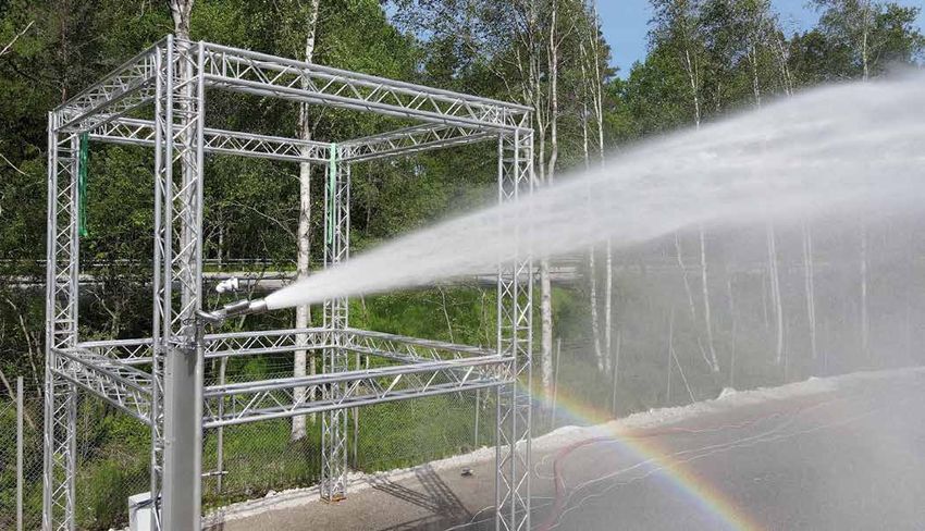
NEVER POINT THE FORCE 50 OR ANY Robotic nozzle DIRECTLY AT HUMANS
WHILE WATER IS SPRAYING THROUGH IT, as doing so can result in serious injury
or possibly death. The FORCE 50 is capable of directing flows of up to approximately
2000 liters per minute (540 gallons per minute) at pressures of up to 12 bars (175 psi)
and has a maximum throwing range of up to approximately 65 meters (70 yards). Such
forces are very dangerous and capable of producing serious injury or death to persons
and serious damage to property. They are also capable of throwing objects with ex-
treme force and velocity into other objects or persons. Accordingly, only professional,
WARNING trained firefighters or other qualified individuals may operate this equipment after being
thoroughly familiar with the Manual, and always by exercising extreme caution to avoid
hitting people or lose objects with the water (or other fluid) stream.
BE SURE THAT THE ROBOTIC NOZZLE IS TIGHTLY AND PROPERLY SECURED
AT ALL TIMES DURING OPERATION! Serious injury or death can occur if the robotic
nozzle is not fully and properly secured and supported. Be sure that the mounting pipe
for the FORCE 50 robotic nozzle is capable of withstanding a nozzle reaction force of at
least eight thousand (8,000) Newtons (800 kgf). The FORCE 50 robotic nozzle should
WARNING not be used on a portable stand of any kind, as such use can be extremely dangerous
and can result in Serious Injury or Death.
UNIFIRE FORCE 50 Robotic Nozzle                                                                         WARNINGS
Installation and setup manual                                                                            FORCE 50
                                                                                             REV. 2.2    2021-02-04
                                                                                                                1-2

                      The FORCE 50 IS HEAVY. Use caution and assistance when installing and take care
                      to avoid injury to your back. Seek assistance to help support and twist the robotic
                      nozzle during installation and take care to avoid injury to your back during handling and
  WARNING             installation.

                      NEVER USE THE ROBOTIC NOZZLE AT PRESSURES HIGHER THAN 12 BARS
                      (175 PSI). The maximum operating pressure for the FORCE 50 robotic nozzle is 12
                      bars (175 psi). Use of the FORCE 50 at pressures higher than 12 bars is dangerous
                      and can lead to serious injury or death or may damage the robotic nozzle. Moreover,
                      the recommended operating pressure of the FORCE 50 is between 7 and 8 bars (100
  WARNING             and 115 psi), which also will provide optimal performance.

                      ONLY MOUNT THE FORCE Robotic nozzle SO THAT ITS BASE IS PERPENDICU-
                      LAR TO THE GROUND. DO NOT install the robotic nozzle at an angle or upside-down
                      without the specific prior written consent of Unifire AB. Doing so may cause damage to
  WARNING             the robotic nozzle gears and motors, which could lead to malfunction.

                      FOLLOW ALL MAINTENANCE & INSPECTION PROCEDURES in this manual.

  WARNING

                      Be sure to use the proper type and size of threads at the robotic nozzle base and
                      also between the robotic nozzle and nozzle (if using a nozzle not supplied by Unifire
                      specifically for use with this robotic nozzle). Use of the wrong type or size of threads will
                      result in an improper connection which can cause leaking and also may cause the ro-
                      botic nozzle and/or nozzle to dislodge under high pressure, possibly leading to serious
  WARNING             injury or death to persons and/or serious damage to property. If you have any doubts as
                      to the exact thread supplied by Unifire, contact Unifire for clarification prior to connect-
                      ing the robotic nozzle and nozzle.

                      KEEP A SAFE DISTANCE DURING OPERATION AND MOVEMENT. The FORCE
                      50 Robotic nozzle has moving parts. Be sure to keep a safe distance from the robotic
                      nozzle as it moves and keep hands and fingers away from pinch points to avoid injury.
  WARNING

                      AVOID RAPID CHARGING. Rapid charging of the robotic nozzle is potentially danger-
                      ous and can cause serious injury to persons and/or property and may cause damage
                      to the robotic nozzle. Charge the robotic nozzle slowly to avoid creating a potentially
                      dangerous, high-pressure surge.
  WARNING
WARNINGS                                                                           UNIFIRE FORCE 50 Robotic Nozzle
FORCE 50                                                                                 Installation and setup manual
REV. 2.2    2021-02-04
1-3

                         USE ONLY UNIFIRE-APPROVED NOZZLES / NOZZLE TIPS. The FORCE 50 was
                         designed for use with the Unifire INTEG 50 and Unifire Smooth Bore nozzles. Use of
                         any nozzle other than a Unifire nozzle made for the FORCE 50 without specific, written
                         approval in advance by Unifire AB constitutes misuse of the product and could affect
                         the safety, performance and/or operation of the robotic nozzle. Such malfunctions could
   WARNING               also result in the nozzle coming loose and being rapidly ejected with high force, which
                         could cause serious injury or even death.

                         DO NOT OPERATE IN EXPLOSIVE ZONES OR ENVIRONMENTS! The electric
                         motors and other components are potential ignition sources and could spark ignition if
                         used in explosive environments. The FORCE 50 is not approved for operation in explo-
   WARNING               sive environments and therefore it should never be used in such environments.

                         DO NOT IMMERSE EQUIPMENT IN WATER. Do not immerse the robotic nozzle,
                         its control box (the TARGA PLC) nor the joystick in water and be sure to keep water
                         out of their interiors. Unifire’s robotic nozzles, and joystick are designed to withstand
                         moderate exposure to rain and water splashing during normal use of the robotic nozzle.
                         Prolonged or extreme exposure to water, including submersion, however, will cause
                         damage and could also cause electrical shock resulting in injury.
   WARNING
                         The TARGA PLC must be installed protected form water and dust. IP67 rated enclosure
                         is optional.

                         Do not use the electrical controls during operation of the emergency manual override
                         cranks as doing so could cause injury.

   WARNING

                         ONLY USE THE MANUAL OVERRIDE IN CASE OF TRUE EMERGENCY & POWER
                         FAILURE. The manual override controls on the FORCE 50 are not designed for normal
                         operation and should only be used in the case of extreme emergency and when the re-
                         mote control feature is not working sufficiently to control the robotic nozzle by means of
   WARNING               the electronic controls. In case of use in such an emergency, first disconnect the cables
                         from the motor connections. !!

                         DISCONNECT POWER PRIOR TO INSTALLATION, MAINTENANCE OR REPAIR.
                         Prior to installation, maintenance or repair be sure to disconnect power and disable
                         flow.

   WARNING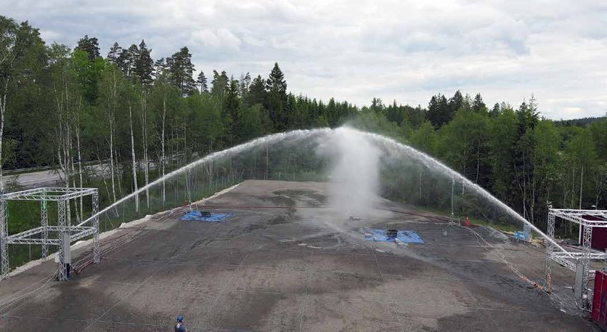
UNIFIRE FORCE 50 Robotic Nozzle                                                                         WARNINGS
Installation and setup manual                                                                            FORCE 50
                                                                                             REV. 2.2    2021-02-04
                                                                                                                1-4

                      Be sure to use the proper type and size of threads at the robotic nozzle base and also
                      between the robotic nozzle and nozzle (if using a nozzle not supplied by Unifire specifi-
                      cally for use with this robotic nozzle). Use of the wrong type or size of threads will result
                      in an improper connection which can cause leaking and also may cause the robotic
  WARNING             nozzle and/or nozzle to dislodge under high pressure, possibly leading to serious injury
                      or death to persons and/or serious damage to property. If you have any doubts as to
                      the exact thread supplied by Unifire, contact Unifire for clarification prior to connecting
                      the robotic nozzle and nozzle.

                      The FORCE 50 is heavy. EXERCISE caution and SEEK assistance when installing
                      and take care to avoid injury to your back. Seek assistance to help support and twist
                      the robotic nozzle during installation and take care to avoid injury to your back during
                      handling and installation.
  WARNING

                      BE SURE THAT THE FORCE 50 IS TIGHTLY AND PROPERLY SECURED AT ALL
                      TIMES DURING OPERATION! Serious injury or death can occur if the robotic nozzle
                      is not fully and properly secured and supported. Be sure that the mounting pipe for the
                      FORCE 50 is capable of withstanding a nozzle reaction force of at least eight thousand
  WARNING             (8,000) Newtons (800 kgf). The FORCE 50 robotic nozzle should not be used on a
                      portable stand of any kind, as such use can be extremely dangerous and can result in
                      Serious Injury or Death.

                      NORMALLLY MOUNT THE FORCE Robotic nozzle SO THAT ITS BASE IS PERPEN-
                      DICULAR TO THE GROUND.

  WARNING             If you plan to install the robotic nozzle at an angle or upside-down, please consult UNI-
                      FIRE when ordering. Special gear ratio and programming may be required.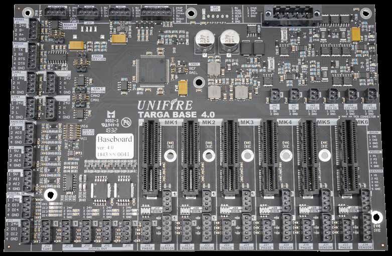
INTRODUCTION                                                                            UNIFIRE FORCE 50 Robotic Nozzle
FORCE 50                                                                                      Installation and setup manual
REV. 2.2    2021-02-04
2-1

                                       INTRODUCTION to this Manual

UNIFIRE FORCE 50 system
This installation and setup manual is intended to provide     For further info please see Unifire Robotic Nozzle catalogue
generic guidance for installation and commissioning of the    And visit our websites:
UNIFIRE FORCE 50 system, including the TARGA Robotic
Nozzle PLC and the Ammolite User Interface,                   www.unifire.com
                                                              www.roboticnozzles.com

Your system is delivered with user specific functions that    www.automaticfirefighting.com
can be different than what is described in this manual.       and
Therefore it is important that you reference the order-spe-
                                                              www.youtube.com/unifireab
cific documents provided with the delivery.
This can include custom I/O. terminal socket specification,
M12 pin-specifications and special customer specific          Also refer to the system specific documentation
software.
UNIFIRE FORCE 50 Robotic Nozzle                           INTRODUCTION
Installation and setup manual                                  FORCE 50
                                                   REV. 2.2    2021-02-04
                                                                      2-2

ACRONYM DEFINITIONS
Table 1 defines the acronyms in the user manual.
TABLE 1: ACRONYM DEFINITIONS

 Acronym     Definition
 AFS         Autonomous fire suppression
 AHJ         Authority having jurisdiction
 DSP         Digital signal processor
 dm          Decimeter
 ft          Foot (or Feet)
 FACP        Fire alarm control panel
 HR          Horizontal range
 IR          Infrared
 kg          Kilogram
 lb (lbs)    Pound(s)
 m           Meter
 mm          Millimeter
 Lpm         Liters per minute
 PLC         Programmable logic controller
 VDC         Volts of direct current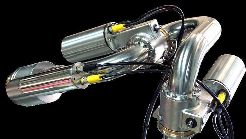
PLANNING                                                                     UNIFIRE FORCE 50 Robotic Nozzle
FORCE 50                                                                           Installation and setup manual
REV. 2.2    2021-02-04
3-1

                         TABLE OF CONTENTS
                         WARNINGS

                         INTRODUCTION TO THIS MANUAL
                          ACRONYM DEFINITIONS                                   2-2

                         PLANNING - BEFORE INSTALLATION
                          About This Manual                                     3-2
                          Contacts                                              3-2
                          APPROVALS AND STANDARDS                               3-2
                          SAFETY warnings                                       3-2
                          Authorized Personnel                                  3-2
                          Structural Alterations                                3-2
                          System Limitations                                    3-4
                          Building Construction                                 3-4
                          Determining a Location                                3-4
                          Water connection                                      3-4

                         MECHANICAL INSTALLATION
                          INSTALLATION GEOMETRY OPTIONS                         4-1
                          Wall, normal orientation                              4-1
                          Wall, inverted orientation                            4-2
                          Ceiling, hanging orientation                          4-3
                          Installation on the wall                              4-4
                          Installation hanging from the ceiling                 4-4
                          Installing The Robotic Nozzle                         4-5

                         FLOW SETTINGS
                          Nozzle Flow Setting                                   5-1
                          Flow chart                                            5-2
                          Reach chart                                           5-3

                         ELECTRICAL INSTALLATION
                          Generic system overview                               6-1
                          Connecting the FORCE 50 to the TARGA PLC              6-2
                          TARGA PLC generic pin-specification                   6-3
                          TARGA Robotic Nozzle PLC TERMINAL SOCKETS             6-4
                          GENERIC TERMINAL SOCKET SPECIFICATION                 6-4

                         SOFTWARE & CALIBRATION
                          Calibrating the Robotic Nozzle’s operating range      7-1
                          Ammolite Software Introduction                        7-3
                          Connect your PC or TABLET                             7-4

                         TECHNICAL SPECIFICATIONS SYSTEM COMPONENTS
                          FORCE 50 QUICK SPECIFICATIONS                         8-1
                          TARGA™ PLC SPECIFICATIONS                             8-3
                          TARGA PLC DIMENSIONS                                  8-4
                          X-TARGA™ & X-TARGA-S                                  8-5
                          Unifire TARGA PCB                                     8-7
                          TARGA PCB                                             8-7
                          Unifire Web Server                                    8-9
                          CAN Bus Cape                                         8-11
                          BLDC Driver Card                                     8-12
                          ONE Graphical User Interface                         8-13
                          π™ (Pi) CAN bus Joystick                             8-15
                          POINTER™ Synchron Joystick                           8-16
                          BLDC Motors                                          8-17
                          FORCE 50 SPARE PARTS                                 8-18
                          Custom Solutions                                     8-19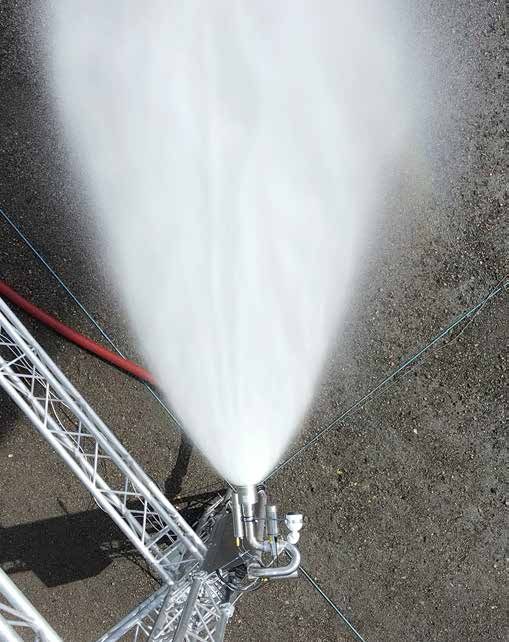
UNIFIRE FORCE 50 Robotic Nozzle                                                                                 PLANNING
Installation and setup manual                                                                                   FORCE 50
                                                                                                    REV. 2.2    2021-02-04
                                                                                                                       3-2

PLANNING - BEFORE INSTALLATION

About This Manual
This manual is a comprehensive guide that contains the          SAFETY warnings
information necessary to design, install, operate, and
maintain the FORCE 50 Robotic Nozzle system.                    A properly designed and installed FORCE 50 Robotic
                                                                Nozzle should not present any significant health or safety
Users of this manual are assumed to be competent fire           problems. Take basic precautions to avoid accidents. The
engineers with a basic knowledge of such systems. Users         various aspects of the system’s operation must be under-
who are not familiar with the equipment should first read the   stood. Observe best practices.
complete manual.
Only certified personal who have undergone UNIFIRE AB
training are allowed to install this equipment.

                                                                Do not operate this device without a full understanding and
Contacts                                                        comprehension of this manual. Personnel responsible for
Should any part of this manual not be understood, or there      the FORCE 50 system must be fully trained on the system
are queries concerning the system, contact UNIFIRE AB           components.
Technical Support using the following details:
UNIFIRE AB,
Bultgatan 40B
442 40 KUNGÄLV                                                  The installer should pay specific attention to the danger,
SWEDEN                                                          caution, warning, and notice statements in this manual.
                                                                Failure to observe safety warnings could cause serious
Mail: support@unifire.com                                       injury, and potentially create liability.

www.unifire.com

                                                                Do not direct the flow stream towards people as it could
                                                                result in serious personal injury or death.
APPROVALS AND STANDARDS
                                                                • Operate and maintain the FORCE 50 Robotic Nozzle
See Section 2 System Components for approval and listing
                                                                   system in compliance with this document and with appli-
information for the various components.
                                                                   cable standards, in addition to the standards of any other
                                                                   authorities having jurisdiction (AHJ). Failure to do so
                                                                   impairs the proper operation and integrity of this device.
                                                                • The owner must maintain the fire protection unit or system
                                                                   and devices in proper operating conditions.
                                                                • Do not, under any circumstance, operate this system
                                                                   outside the water flow or pressure range indicated in this
                                                                   manual.
                                                                • The owner must ensure that an uninterrupted supply of
                                                                   water is maintained to the Robotic Nozzle.

                                                                Authorized Personnel
                                                                The FORCE 50 system shall be installed by
                                                                authorized personnel certified by UNIFIRE AB. Use compo-
                                                                nents and accessories authorized only by UNIFIRE AB.

                                                                Structural Alterations
                                                                This installation manual details the suggested installation
                                                                method. Any structural alteration necessary for installation
                                                                must comply with local building code requirements.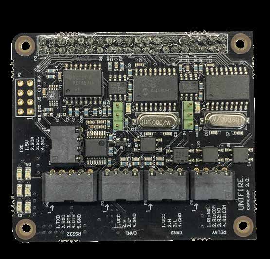
PLANNING                                                     UNIFIRE FORCE 50 Robotic Nozzle
FORCE 50                                                           Installation and setup manual
REV. 2.2    2021-02-04
3-3

DO NOT PRESSURIZE THE UNIT until the flange has been
properly tightened.

DO NOT PRESSURIZE THE UNIT until the electrical
installation and software calibration procedure has been
completed

DO NOT PRESSURIZE THE UNIT until the system commis-
sioning has been completed by certified technicians, and a
formal release note / approval has been issued.
UNIFIRE FORCE 50 Robotic Nozzle                                                                                    PLANNING
Installation and setup manual                                                                                      FORCE 50
                                                                                                       REV. 2.2    2021-02-04
                                                                                                                          3-4

System Limitations                                                  Determining a Location
The system designer shall take into account the building            Contact your local technical support team for assistance in
construction or vehicle requirements, location, hydraulic           determining the optimal location of the system components.
design, coverage area, and number of systems required. If
the limitations in these areas are not maintained, the system
may not operate correctly.

Building Construction                                               Water connection

• Water demand: Evaluate the FORCE 50 water system                 The FORCE 50 is normally delivered with a DN50/PN16
   demand as an independent addition to the existing                stainless steel flange.
   building water supply. Conduct a hydraulic analysis to           Options include 2” male BSP, JIS and ANSI flanges, and
   ensure that it does not affect the building’s existing water     customer specific brackets.
   system design criteria. It is possible to achieve this without
                                                                    Please discuss the connection with your sales represen-
   significant system supply modifications. However, the
                                                                    tative and please specify the requested connection when
   system may require increased pump sizes, storage tank
                                                                    ordering.
   capacity, and pipe sizes.
MECHANICAL INSTALLATION UNIFIRE FORCE 50 Robotic Nozzle
FORCE 50 Installation and setup manual
REV. 2.2 2021-02-04
4-1
MECHANICAL INSTALLATION The Robotic Nozzle can be installed with
Wall, Normal orientation
INSTALLATION GEOMETRY OPTIONS
Wall, Inverted orientation
The FORCE 50 Robotic Nozzle can be installed geometri- Ceiling, hanging orientation
cally in three different orientations:
Wall, normal orientation
Use when the water supply comes from below
Use when the Robotic Nozzle is installed on a wall,
allowing a maximum of 180° horizontal and +/- 90° vertical
movement .The TARGA PLC must be installed next to the
Robotic Nozzle
CAUTION!
This orientation is suitable for manual operation with
Joystick. This is standard geometry.UNIFIRE FORCE 50 Robotic Nozzle MECHANICAL INSTALLATION
Installation and setup manual FORCE 50
REV. 2.2 2021-02-04
4-2
Wall, inverted orientation
Use when the water supply comes from above.
Use when the Robotic Nozzle is installed on a wall,
allowing a maximum of 180° horizontal and +/- 90° vertical
movement
The TARGA PLC must be installed next to the Robotic
Nozzle.
This geometry is suitable for manual operation with Joystick
CAUTION!
For inverted orientation the geometry of the FORCE 50
must be inverted, hence please advise the required orien-
tation / geometry when ordering.MECHANICAL INSTALLATION UNIFIRE FORCE 50 Robotic Nozzle FORCE 50 Installation and setup manual REV. 2.2 2021-02-04 4-3 Ceiling, hanging orientation Installing the Robotic Nozzle hanging from the ceiling This orientation is not suited for manual operation with a usually provide the best reach and coverage. Joystick or the ONE App. The Robotic Nozzle can be installed in the center of the area covered by the detector, thus allowing a full 360° coverage of up to 70 m Ø (35 m reach in all directions) This is usually the prefered orientation for autonomous systems - when the FORCE 50 is controlled from detectors or a Thermal imaging system.
UNIFIRE FORCE 50 Robotic Nozzle                                                                 MECHANICAL INSTALLATION
Installation and setup manual                                                                                   FORCE 50
                                                                                                    REV. 2.2    2021-02-04
                                                                                                                       4-4

                          s
                     eter
                35 m

                                                           50 meters

Installation on the wall

Usually provides easier access, thus it makes installation easier. The cover is limited to only 180° horizontal reach.
An area of up to 40 m radius is protected. Installing on a wall provides a geometry suited for manual Joystick control.
                  eters
                35 m

                                                              50 meters

Installation hanging from the ceiling

Is recommended for fully automatic systems. It usually will provide better reach, the stream is less obstructed by objects on
the floor. Up to 40 m reach provide a full 80 meter Ø cover. It is however difficult to control with a manual Joystick, because
the geometry is rotated 90°, with the Nozzle facing straight down in default position.
MECHANICAL INSTALLATION UNIFIRE FORCE 50 Robotic Nozzle
FORCE 50 Installation and setup manual
REV. 2.2 2021-02-04
4-5
Installing The Robotic Nozzle
By now we assume you have decided if the Robotic Nozzle
is to be installed on the wall, or hanging from the ceiling.
The FORCE 50 Robotic Nozzle is fitted with a DN50/PN16
flange (or similar size 2” ANSI flange or JIS flange).
! WARNING
The maximum reaction force at 2000 lit/min and 10 bar is
1400 N. The mounting pipe and bracket must withstand
minimum 8 000 N of Force, to provide a safe and stable
base.
The flange itself provides the required support to hold
the FORCE 50. Additional support and brackets must be
applied to the feeding pipe to keep it stable under operation.
This is especially important during fully automatic operation.
Use suitable M16 bolts and a flat seal to install the flange.
! CAUTION
Clearance!!
Take special precaution to ensure the Robotic Nozzle can
move and rotate freely +/- 90° in all directions
Make sure there are no obstructions with 600 mm from the The FORCE 50 weighs 19 Kg incl flange and nozzle
centre of rotation
Clearance behind/above minimum 350 mm
Clearance each side 600 mm Clearance each side 600 mmUNIFIRE FORCE 50 Robotic Nozzle MECHANICAL INSTALLATION
Installation and setup manual FORCE 50
REV. 2.2 2021-02-04
4-6FLOW AND REACH UNIFIRE FORCE 50 Robotic Nozzle
FORCE 50 Installation and setup manual
REV. 2.2 2021-02-04
5-1
FLOW SETTINGS
Nozzle Flow Setting
The Nozzle flow can easily be selected by fitting the
appropriate flow shim.
The shim is custom manufactured (3D printed) to fit each
order.
Please specify your required flow at your system pressure
when ordering.
FLOW SHIMS
Flow shims are 3D printed specifically to order.
Typically in dimension (thickness) 0,8-6,2 mm
See flow and reach charts on the following pagesUNIFIRE FORCE 50 Robotic Nozzle FLOW AND REACH
Installation and setup manual FORCE 50
REV. 2.2 2021-02-04
5-2
Flow chart
FORCE 50 with INTEG 50
LPM Flow with various flow shims
Shim
2200 size
mm
2100
2000
6,125
1900
1800 5,25
1700
1600 4,375
1500
1400
3,71(K30)
1300 3,5
1200
3,23
1100 2,62
1000
900
800 1,75
700
600
500
400 0,875
300
200
100
0 1 2 3 4 5 6 7 8 9 10 BarFLOW AND REACH UNIFIRE FORCE 50 Robotic Nozzle
FORCE 50 Installation and setup manual
REV. 2.2 2021-02-04
5-3
Reach chart
FORCE 50 with INTEG 50
Max reach at 35° discharge angle
Meters Shim
size
mm
65
6,125
5,25
60
4,375
3,5
55
2,62
50
1,75
45
40
0,875
35
30
25
20
15
0 1 2 3 4 5 6 7 8 9 10 BarUNIFIRE FORCE 50 Robotic Nozzle FLOW AND REACH
Installation and setup manual FORCE 50
REV. 2.2 2021-02-04
5-4ELECTRICAL INSTALLATION UNIFIRE FORCE 50 Robotic Nozzle
FORCE 50 Installation and setup manual
REV. 2.2 2021-02-04
6-1
ELECTRICAL INSTALLATION
Generic system overview
Below is a generic example of what a system can look like.
The TARGA Robotic Nozzle PLC is a highly capable
A DHCP Router is required to set up the system with the
programmable PLC. With support for up to 6 x BLDC drivers
Ammolite GUI. This will also allow for the ONE App to be
activated
Communication Protocols: 2 x CAN 2.0 29-bit header Over the web interface the systems can be remote
(UniCAN) 125,250,500 kB/s, RS232, RS485 (Modbus, controlled and remotely configured and monitored. From
DMX, etc.) anywhere in the world.
Physical Layer Protocols: USB, Ethernet (TCP/IP, web A cabled Canbus Joystick can be connected for local
socket), others available per customer requirements control.
6 BLDC Motor Driver Card Slots (optional: slots for DO or An industrial radio remote control (Hetronic ERGO-S) can
DI/AI expansion cards) also be locally connected.
Inputs: 4 digital inputs (NPN) + 2 per installed motor driver Digital and analogue outputs are generic and can be used
card, 6 analogue inputs (4-20 mA or 0-5V), to operate valves, and send or receive status signals.
expandable & customizable to customer requirements
Outputs: 8 digital outputs, of which 4 can be set to PWM.
Ammolite GUI
ONE App
TARGA PLC with web server
+V +V -V -V P+ P-
MEAN WELL
SDR-480P-24
INPUT: 100-240 VAC 5.0A
+ +V ADJ
GND N L
A2 A2 A2 21
11
A1 A1 A1
41
V V V
CANBUS (Joystick) ROTATION VERTICAL NOZZLE
RJ45
V
20A 14 14 14
1A
11 11 11
12 12 12 2A
1 2 3 4 5 6 7 8 9 10 11 12 13 14 15 16 17 18 19 20 21 22 23 24
Radio Remote
230VAC
ROXTEC EzEntry 10 (motor cables and relay etc..
100-230VAC
Valve output
Canbus Joystick
M12 Multicables
Digital outputs
Digital inputs
Analogue inputs
Canbus transcieverUNIFIRE FORCE 50 Robotic Nozzle ELECTRICAL INSTALLATION
Installation and setup manual FORCE 50
REV. 2.2 2021-02-04
6-2
Connecting the FORCE 50 to the TARGA PLC
The FORCE 50 system is fitted with M12 multi connector. Yellow A-coded connectors are for the BLDC Motor Sensors
The standard system is delivered with 5-meter M12 cables .
Black B-coded connectors are for the BLDC Motor Phases.
Connect the 6 x 5 meter M12 cables from the PLC to the
Robotic Nozzle The key-coding makes it impossible to accidentally cross
From left to right: Rotation, Vertical, Nozzle the cables.
Cables to Vertical (MK5)
Cables to Nozzle (MK6)
Cables to Rotation (MK4)ELECTRICAL INSTALLATION UNIFIRE FORCE 50 Robotic Nozzle
FORCE 50 Installation and setup manual
REV. 2.2 2021-02-04
6-3
TARGA PLC generic pin-specification
Canbus Rotation 5P Vertical 5P Nozzle 5P
Joystick MK4 MK5 MK6
5P 5-PIN (SENSORS) 5-PIN (SENSORS) 5-PIN (SENSORS)
I/O 1 I/O 2 Rotation 4P Vertical 4P Nozzle 4P
MK4 MK5 MK6
5P Dig.Out 5P In/Out 4-PIN (PHASES) 4-PIN (PHASES) 4-PIN (PHASES)
5-PIN A-coded (sensors) Joystick BLDC sensors M12 A-coded 5-pin
1 - BROWN
5 5P Canbus Rotation / Vertical / Nozzle
2 - WHITE 1 2 P1 Shield P1 GND
3 - BLUE P2 24 VDC P2 5 VDC
4 - BLACK
P3 GND P3 HALL 3
5 - GREY 4 3
P4 CAN H P4 HALL 2
P5 CAN L P5 HALL 1
M12 5, 8 or 12-pin BLDC phases M12 B-coded 4-pin
4-PIN B-coded Dig In/Out Rotation / Vertical / Nozzle
(phases)
1 - BROWN
1 2 P1 generic P1 PHASE 1
2 - n/a P2 generic P2 not connected
3 - BLUE P3 generic P3 PHASE 2
4 3
4 - BLACK
P4 generic P4 PHASE 3
5 - n/a
P5 generic P5 not connectedUNIFIRE FORCE 50 Robotic Nozzle ELECTRICAL INSTALLATION
Installation and setup manual FORCE 50
REV. 2.2 2021-02-04
6-4
TARGA Robotic Nozzle PLC TERMINAL SOCKETS
RITTAL 1045500
GENERIC TERMINAL SOCKET SPECIFICATIONSOFTWARE & CALIBRATION UNIFIRE FORCE 50 Robotic Nozzle
FORCE 50 Installation and setup manual
REV. 2.2 2021-02-04
7-1
SOFTWARE & CALIBRATION
Calibrating the Robotic Nozzle’s operating range Wall mounted Nozzle
Before attempting to operate, the Robotic Nozzle must be For wall mounted system, the origo/default position is
calibrated = given an operating range. normally that the Nozzle is pointing center (with +/.90°
The calibration is performed through the Ammolite user horizontal movement), and level to ground (with +/-90°
interface as described in this section. vertical movement)
Calibrate operating range by following step 1-22 as set out
on the following pages.
90°
90°
WALL (view from above)
90°
90°
Max vertical range is +/-90° if there are no mechanical Max horizontal range is 360° if there are no mechanical
obstructions. obstructions.UNIFIRE FORCE 50 Robotic Nozzle SOFTWARE & CALIBRATION
Installation and setup manual FORCE 50
REV. 2.2 2021-02-04
7-2
Ceiling mounted Nozzle
For ceiling mounted system, the origo/default position is
normally that the Nozzle is pointing straight down on both
axes.
Please follow the step-by-step instructions on the following
pages to calibrate the operating range.
CEILING (view from the side) CEILING (view from the side)
90° 90°
90° 90°SOFTWARE & CALIBRATION UNIFIRE FORCE 50 Robotic Nozzle FORCE 50 Installation and setup manual REV. 2.2 2021-02-04 7-3 Ammolite Software Introduction Unifire FORCE 50 set up is achieved through our web browser-based graphical user interface (GUI) called “Ammolite™ The Unifire TARGA ROBOTIC NOZZLE PLC connects to a standard TCP/IP based network. The built-in web server has been set up to be assigned an IP address by an external DHCP server. This can be a local router or a dedicated server in a larger network, administered by your IT department or similar. To connect to the web-server, open a browser Chrome or Firefox and enter the IP address followed by :81 (ex: http://192.168.0.45:81, replace 192.168.0.45 with the actual IP). Enter the username and password provided for your system to access the setup environment. It is required that you make a note in the service log at login.
UNIFIRE FORCE 50 Robotic Nozzle                                 SOFTWARE & CALIBRATION
Installation and setup manual                                                   FORCE 50
                                                                    REV. 2.2    2021-02-04
                                                                                       7-4

Connect your PC or TABLET

Connect your PC or Tablet by WiFi or cable to the same
network as the TARGA PLC.
Find IP address of the TARGA PLC as automatically
assigned by the DHCP server
Enter the IP address, followed by :81 in the browser
window.

For example: http://192.186.0.45:81

Then follow instructions to calibrate on the following pages.

                   NETWORK

                   DHCP Server on
                     Local Router
                        or LAN

                                             WiFi
SOFTWARE & CALIBRATION UNIFIRE FORCE 50 Robotic Nozzle FORCE 50 Installation and setup manual REV. 2.2 2021-02-04 7-5 1) Open your web-browser (Safari, Chrome, Firefox or other...) 2) Enter the IP Address of the TARGA PLC, followed by :81 (for example http://192.168.0.217:81). Push Enter.
UNIFIRE FORCE 50 Robotic Nozzle                                   SOFTWARE & CALIBRATION
Installation and setup manual                                                     FORCE 50
                                                                      REV. 2.2    2021-02-04
                                                                                         7-6

3) Enter the username and password provided with your delivery.

4) In this example it is “service” and “service”. Click Login.
SOFTWARE & CALIBRATION UNIFIRE FORCE 50 Robotic Nozzle FORCE 50 Installation and setup manual REV. 2.2 2021-02-04 7-7 5) You are now requested to make a note in the service log. 6) So... for the example we write, “Calibration”.... “First start up”. Any text can be entered. Click OK.
UNIFIRE FORCE 50 Robotic Nozzle                                                       SOFTWARE & CALIBRATION
Installation and setup manual                                                                         FORCE 50
                                                                                          REV. 2.2    2021-02-04
                                                                                                             7-8

7) This opens up the start page of Ammolite. To initiate calibration of the operating range, click “Advanced”.

8) This opens up the section Advanced settings. Next click “Hardware”.
SOFTWARE & CALIBRATION UNIFIRE FORCE 50 Robotic Nozzle
FORCE 50 Installation and setup manual
REV. 2.2 2021-02-04
7-9
Typically:
Horizontal
Vertical
Jet/Spray
9) This open up the Motor page. You can read the position of the motors, calibrated max, actual real time
current draw (A), and Motor Status.
MK4 is usually horizontal, MK5 usually vertical, and MK6 usually nozzle jet/spray)
10) To calibrate Motor 4 (horizontal), click “Calibrate”.UNIFIRE FORCE 50 Robotic Nozzle SOFTWARE & CALIBRATION
Installation and setup manual FORCE 50
REV. 2.2 2021-02-04
7-10
11) Select Min/Max method that allows you to freely select any operating range. (Center method is used only
for special applications when the operating range is preset in the software)
12) Run the motor to the required Min position (left arrow), by using either the buttons on the screen (for tab-
lets), or using the right/left arrow key on your PC Keyboard. Once you have the position, Click “Set new min”SOFTWARE & CALIBRATION UNIFIRE FORCE 50 Robotic Nozzle
FORCE 50 Installation and setup manual
REV. 2.2 2021-02-04
7-11
The same value
Confirms correct
13) Run the motor to the required Max position (right arrow). Now the “Current position should read a val-
ue typically between 2 000 and 50 000. Click set new Max.
14) Next, you see this notice, confirming successful calibration.UNIFIRE FORCE 50 Robotic Nozzle SOFTWARE & CALIBRATION
Installation and setup manual FORCE 50
REV. 2.2 2021-02-04
7-12
15) Repeat steps 10 - 15 for Motor 5 (vertical)
16) Calibrate Motor 6 (nozzle jet/spray) in the same manner as you did the other motors, but follow the
instructions in step 17 on the next pageSOFTWARE & CALIBRATION UNIFIRE FORCE 50 Robotic Nozzle
FORCE 50 Installation and setup manual
REV. 2.2 2021-02-04
7-13
Set the nozzle minimum (Motor 6), just before mechanical stop.
This is effectively selecting the max spray angle, and here you can limit the maximum spray allowed.
Set nozzle maximum (Motor 6), just before mechanical stop.
This is effectively selecting the straight stream.
Here you can block the straight stream by setting the
Maximum to - say - 10 ° spray, and thereby avoid a straight steam.
This is useful when the required reach is short, and you want to avoid a hard-hitting straight steam all together.
17) Calibrate Motor 6 (jet/spray nozzle) as Motor 4 and Motor 5UNIFIRE FORCE 50 Robotic Nozzle SOFTWARE & CALIBRATION
Installation and setup manual FORCE 50
REV. 2.2 2021-02-04
7-14
18) Next you can test the motors and calibrated range directly form your PC. Click “Test motors”.
19) Check the box for each motor you want to run.SOFTWARE & CALIBRATION UNIFIRE FORCE 50 Robotic Nozzle
FORCE 50 Installation and setup manual
REV. 2.2 2021-02-04
7-15
You need to
choose. Left Right
20) Then actively choose key pair. (This must be done.)
21) Now you can run the motors with the selected key pair.UNIFIRE FORCE 50 Robotic Nozzle SOFTWARE & CALIBRATION
Installation and setup manual FORCE 50
REV. 2.2 2021-02-04
7-16
22) Calibration is now complete and you can exit Test Motors and Ammolite.TECHNICAL
8-1 F O R C E 5 0SPECIFICATIONS UNIFIRE FORCE 50 Robotic Nozzle
FORCE 50 Installation and setup manual
REV. 2.2 2021-02-04
8-1
TECHNICAL SPECIFICATIONS SYSTEM COMPONENTS
FORCE 50 QUICK SPECIFICATIONS
2” ROBOTIC NOZZLE
Max Flow: 2 100 liters (555 gallons) per minute; 126 m3/hr
Type: Remote Controlled
Material: Stainless Steel 316L
Range of Motion: 360º rotation / 180º vertical movement
Base Connection: 2” Male BSP or flange (ANSI, DIN, JIS)
Nozzle Tip Connection: 2” Male BSP
Motor Type: 24V Brushless DC (BLDC)
Certificates: Bureau Veritas (BV) Type Approval / CE Marked /
Manufactured at ISO 9001:2015 Certified Facilities
Metric Imperial
Int. Pipe Diameter: 50 mm 2” inches
Dimensions (w/ Integ nozzle): 25 x 35 x 58 cm 9.8” x 13.8” x 22.8” inches
Weight (w/ Integ nozzle): 19 kg 42 lbs
Max. Flow: 2 100 lpm 555 gpm
Max. Reach: 65 meters 71 yards
Max. Working Pressure: 12 bar 174 psi
Nominal Operating Pressure: 10 bar 145 psiUNIFIRE FORCE 50 Robotic Nozzle TECHNICAL SPECIFICATIONS
FORCE 50 8-2
Installation and setup manual FORCE 50
REV. 2.2 2021-02-04
8-2
FORCE 50 - DETAILED SPECIFICATIONS
ITEM / FEATURE DESCRIPTION
Force 50 BLDC Robotic Nozzle 2” electric 24V brushless motor (BLDC) robotic
Chassis: nozzle (a.k.a. “remote control monitor” or “water
cannon”) suitable for fire fighting.
Made of 316L Stainless Steel (EN1.4404).
Robust and suitable for harsh environments.
Compatible with use of foam, salt-water, and oth-
er harsh agents.
Smooth, large (50mm) pipe bends for minimal
friction loss.
Fully integrated and enclosed stainless steel
worm gears, with Bronze (CuSn12) gear wheels.
Fully enclosed BLDC brushless motors provide
extremely long life, high torque and allow ex-
tremely accurate positioning and position feed-
back.
Modular design for capability of changing dam-
aged pipe sections and gear housings.
Very low-maintenance; never requires re-greas-
ing.
Mass: Approx. 12.5 kg without nozzle tip.
Dimensions (w/ Integ nozzle): 25 x 35 x 58 cm.
Ambient temperature range: -25°C to +70°C.
Flow Range: 500 to 2100 liters (130 to 555 U.S. gallons) per min-
ute; ; 126 m3/hr).. Integ 50 jet/spray tip is mechan-
ically adjustable to accommodate various flows.
JETRANGE 50 tip has interchangeable flow discs
to meet your flow requirements
Max Working Pressure: 12 bar
Nominal Operating Pressure: 10 bar
Maximum Reach: Approximately 65 meters at 2000 liters per min-
ute at 10 bars (71 yards at 530 gpm at 145 psi) in
jet stream mode. Actual results can vary signifi-
cantly depending on a number of factors (wind,
piping, valves, pump, etc.)
Maximum Range of Motion: 360° horizontal; 180° vertical (+/- 90° from hor-
izontal). Range can be easily set to any range
desired. (May be limited if used with POINTER
controller to 270° horizontal / - 20°/+ 70° or other
custom specification. Inquire to learn more.)
Movement Velocity (Speed): Standard: 24°/sec. rotational; 12°/sec. vertical
Optional High Speed: up to 70 or 360 °/sec.TECHNICAL SPECIFICATIONS UNIFIRE FORCE 50 Robotic Nozzle
FORCE 50 Installation and setup manual
REV. 2.2 2021-02-04
8-3
TARGA™ PLC SPECIFICATIONS
Unifire’s Revolutionary PLC for Total System Control
Models: TARGA1, TARGA2, TARGA3, TARGA4, TARGA5 & TARGA6
(digit represents # of installed BLDC driver cards)
Power: 24V DC / 20 Amps
Weight: 1 kg / 2.2 lbs
Dimensions: 225 x 225 x 125 mm / 8.9” x 8.9” x 5” inches
Communication Protocols: 2 x CAN 2.0 29-bit header (UniCAN) 125.250.500 kB/s,
RS232, RS485 (Modbus, DMX, etc.)
Physical Layer Protocols: USB, Ethernet (TCP/IP, web socket), others available per
customer requirements.
BLDC Motor Driver Card 6 (each with 2 digital inputs)
Slots:
Inputs: 4 digital inputs (NPT) + 2 per installed motor driver card,
6 analogue inputs (4-20 mA or 0-5V), expandable & cus-
tomizable to customer requirements
Outputs: 8 digital outputs, of which 4 can be set to PWM, ex-
pandable to customer requirements
Connector Types: M12 A/B coded, 4P, 5P, 8P, 12P
Certificates: CE Marked, Manufactured at ISO Certified facilities.UNIFIRE FORCE 50 Robotic Nozzle TECHNICAL SPECIFICATIONS
Installation and setup manual FORCE 50
REV. 2.2 2021-02-04
TARGA PLC DIMENSIONS 8-4
22.5 cm
cm
.5
22
12.5 cmTECHNICAL SPECIFICATIONS UNIFIRE FORCE 50 Robotic Nozzle
FORCE 50 Installation and setup manual
REV. 2.2 2021-02-04
8-5
X-TARGA X-TARGA-S
RITTAL IP66 Steel Weidmüller IP67
Plate Cabinet Stainless Steel cabinet
X-TARGA™ & X-TARGA-S
Unifire’s Revolutionary, Industrial & Marine PLC
for Total System Control
The X-TARGA is Unifire’s revolutionary TARGA PLC (Programmable Logic Controller),
mounted in one of two choices of IP66 cabinets, both designed for the harshest envi-
ronments and power supply from 110 to 230 V AC at 50 or 60 Hertz., for the total, flex-
ible control of Unifire’s advanced robotic nozzle systems and a virtually-endless variety
of other system peripherals and components. The unique TARGA system allows users
to simply and economically tailor water cannon systems to their individual needs.
From basic, low-cost, stand alone installations, to highly sophisticated and integrated
systems.
Both cabinet types are IP66 rated and designed for the harshest environments, both
on- and off-shore. The X-TARGA comes standard with a built-in power converter from
110 to 230 V AC at 50 or 60 Hertz to TARGA’s native 24VDC / 20 Amp requirement. The
mounted TARGA (see TARGA section of this brochure) is a scaleable system platform
that supports up to six BLDC motors and numerous analogue and digital inputs and
outputs. The Unifire X-TARGA PLC controller for robotic nozzles, valves, lights, periph-
erals, automatic systems, system integration, and much more.
2019 technology allows our customers to control systems from their phone, tablet and
computer, from anywhere in the world. Network systems together and control from a
central control station, and even monitor the system status, learn of any component
failures, and upload system software updates or system function changes requested
from Unifire.UNIFIRE FORCE 50 Robotic Nozzle TECHNICAL SPECIFICATIONS
Installation and setup manual FORCE 50
REV. 2.2 2021-02-04
8-6
X-TARGA(-S) PLC SPECIFICATIONS
Models: X-TARGA & X-TARGA-S (each followed by a number 1-6. rep-
resenting the quantity of installed BLDC driver cards)
Power Input: 110/230 V AC, 50/60 Hz (built-in converter to 24VDC / 20
Amps)
Approximate Weight: 15 kg / 33 lbs.
Cabinet Types: Model: X-TARGA: RITTAL IP66 Steel Plate cabinet type: AE
1045.500, Dimensions: 500 x 400 x 210 mm / 19.7” x 15.8” x 8.3”
inches, mass: 13 kg.
Model: X-TARGA-S: Weidmüller IP67 Stainless Steel cabinet
type: KTB MH 453820 S4E1 Stainless Steel 316L Cabinet, Di-
mensions: 458 x 382 x 200 mm / 18” x 15” x 7.9” inches, mass:
11.54 kg.
Communication Proto- 2 x CAN 2.0 29-bit header (UniCAN) 125,250,500 kB/s, RS232,
cols: RS485 (Modbus, DMX, etc.)
Physical Layer Protocols: USB, Ethernet (TCP/IP, web socket), others available per cus-
tomer requirements
BLD Motor Driver Card 6 (each with 2 digital inputs)
Slots:
Inputs: 4 digital inputs (NPT) + 2 per installed motor driver card, 6
analogue inputs (4-20 mA or 0-5V), expandable & customiz-
able to customer requirements
Outputs: 8 digital outputs, of which 4 can be set to PWM, expandable
to customer requirements
Connector Types: M12 A/B coded, 4P, 5P, 8P, 12P
Certificates: CE Marked, produced at ISO 9000 and 14000 certified facili-
ties
Max altitude Never install the X-TARGA PLC over 4000 meter above sea
levelTECHNICAL SPECIFICATIONS UNIFIRE FORCE 50 Robotic Nozzle
FORCE 50 Installation and setup manual
REV. 2.2 2021-02-04
8-7
TARGA PCB
Unifire TARGA PCB
Many PLC’s (programmable logic controllers) are commercially available on
the market, and are used by many of Unifire’s competitors.
But Unifire won’t settle for standard, off-the-shelf solutions. At Unifire, we
think for ourselves. And, we are very demanding.
Commerically-available PLC’s are bulky, designed to suit a wide variety of
industries and applications, and are therefore over-loaded with bulky elec-
tronics, components and software, markedly reducing efficiency, and often
failing to include key features Unifire demands for its advanced systems.
That is why Unifire has spent years maticulously designing and improving
our own TARGA PCB (printed circuit board), tailor-made for our robotic noz-
zle systems and their peripherals, and to accommodate technologies yet to
come. Our newest generation PCB is cutting-edge technology and provides
a huge range of possibilities, accommodates rapid, dynamic technological
advances, maximizes efficiency in hardware and software design, and is the
perfect solution for total control of our robotic nozzle systems.
Manufactured for Unifire in Sweden at ISO 9001 & 14001 certified, state-
of-the-art facilities, side-by-side with electronics for Ericsson, SAAB Space,
Volvo, and other industry-leading, highly demanding companies.
When quality matters, look to Unifire.UNIFIRE FORCE 50 Robotic Nozzle TECHNICAL SPECIFICATIONS
Installation and setup manual FORCE 50
REV. 2.2 2021-02-04
8-8
Features
The Unifire TARGA PCB is laoded with features, including, to name a few:
• 6 BLDC Motor Driver Slots for the control of brushless motors
• A variety of communication protocols, including 2 x CAN 2.0 29-bit
header (UniCAN) 125,250,500 kB/s, RS232, RS485 (Modbus, DMX, etc.
• USB, Ethernet (TCP/IP, web socket), others available per customer re-
quirements
• 4 digital inputs (NPT) + 2 per installed motor driver card,
• 6 analogue inputs (4-20 mA or 0-5V), expandable & customizable to cus-
tomer requirements
• 8 digital outputs, of which 4 can be set to PWM, expandable to customer
requirements
• Reserved control pins, allows to work with other control boards
• Comes with development resources and manual (examples in wiringPi/
python)TECHNICAL SPECIFICATIONS UNIFIRE FORCE 50 Robotic Nozzle
FORCE 50 Installation and setup manual
REV. 2.2 2021-02-04
8-9
Unifire Web Server
Take Complete Control Of Unifire’s Robotic Nozzle Systems
From Anywhere In The World, Thanks To Our Web Server—
A Full-Blown, Internet-Ready Pc, Built In To Our
Targa Plc, That Fits In The Palm Of Your Hand!!
Welcome to the Internet of Things!
The Unifire Web Server is our optional, full-functioned personal computer
(PC) add-on to our entire line of TARGA PLC’s.
The Unifire web server, combined with our CAN Bus Cape, allows all mod-
els of Unifire’s TARGA PLC’s to come fully online.
Thanks to the Unifire Web Server, our customers have the option of taking
full, secure control of Unifire’s advanced robotic nozzle systems with our
InterAct software and app.
Have a phone? Control our systems. Have a tablet? Control our systems.
Have a computer? Control our systems. Got Internet access? Control our
systems from anywhere in the world!UNIFIRE FORCE 50 Robotic Nozzle TECHNICAL SPECIFICATIONS
Installation and setup manual FORCE 50
REV. 2.2 2021-02-04
8-10
Features
The Unifire Web Server is a key component of Unifire’s InterAct system. Com-
bined with our CANbus Cape. USB Router and InterAct software and Graphical
User Interfacess, adds to Unifire’s advanced robotic nozzle systems a host of
networking and control capabilities, including over the Internet.
Unifire’s already powerful and flexible InterAct graphical user interface can be
custom designed to your specific needs, look, functionas, language and look,
with virtually unlimited flexibility to control systems with advanced logic se-
quences and automated functions.
Specifications
• SOC: Broadcom BCM2837B0, Cortex-A53 (ARMv8) 64-bit SoC
• CPU: 1.4GHz 64-bit quad-core ARM Cortex-A53 CPU
• RAM: 1GB LPDDR2 SDRAM
• Operating system support: Linux and Unix
• WIFI: Dual-band 802.11ac wireless LAN (2.4GHz and 5GHz ) and
Bluetooth 4.2, capable of running at 2.4GHz and 5GHz.
• Ethernet: Gigabit Ethernet over USB 2.0 (max 300 Mbps)
• Thermal management: Yes.
• Power over Ethernet
• Video: Yes – VideoCore IV 3D. Full-size HDMI
• USB 2.0: 4 ports
• Power: 5V/2.5A DC power input
“Here’s to the crazy ones. The misfits. The rebels. The troublemakers. The round pegs in
the square holes. The ones who see things differently. They’re not fond of rules. And they
have no respect for the status quo. You can quote them, disagree with them, glorify or vilify
them. About the only thing you can’t do is ignore them. Because they change things. They
push the human race forward. And while some may see them as the crazy ones, we see
genius. Because the people who are crazy enough to think they can change the world, are
the ones who do.”
— Apple Inc.TECHNICAL SPECIFICATIONS UNIFIRE FORCE 50 Robotic Nozzle
FORCE 50 Installation and setup manual
REV. 2.2 2021-02-04
8-11
CAN Bus Cape
Unifire CAN Bus Cape for Raspberry Pi
Communication Hat with 2x CAN, RS232, I2C and relays.
Technical Overview
The Unifire CAN Cape adds serial networking options to your Raspberry Pi
utilizing the GPIO.
The two onboard CAN Bus ports utilize the Microchip MCP2515 CAN con-
troller, accessible per SPI interface, in combination with the Microchip
MCP2551 CAN transceiver. 120Ω termination is available by jumper or con-
trol over GPIO.
The RS232 port is controlled via the RPi’s UART using the MAX3232 line-
driver and receiver.
The I2C is buffered by LTC4313 and the two onboard photoMOS relays allow
for simple digital control of external equipment. The IO expander for the
I2C bus allows for even further expansions.
Onboard is also a DC/DC transformer allowing the CAN cape to supply the
RPi with power. PoCAN (Power over CAN) makes this possible.
The CAN cape is also equipped with six blue LED indicators.UNIFIRE FORCE 50 Robotic Nozzle TECHNICAL SPECIFICATIONS
Installation and setup manual FORCE 50
REV. 2.2 2021-02-04
8-12
BLDC Driver Card
Unifire BLDC Motor Driver Card
Like all of our electronics, Unifire designed its own BLDC motor
driver card to deliver the functionality and efficiency unique to
Unifire’s robotic nozzle systems.
Unlike competing solutions, Unifire uses 3-phase 24V DC brush-
less (BLDC) motors to control its robotic nozzles. These are the
same motors used in numerous industrial robots — and for good
reason. BLDC motors offer numerous advantages over standard,
“brushed” DC motors used in most competing products., such as
higher torque, higher precision in their control, and much longer
life.
Controlling BLDC motors, however, requires special electronics to
precisely control the three phases sent to the motors. That’s where
Unifire’s unique BLDC motor driver cards come in.
With Unifire’s BLDC motor driver cards, our customers benefit
from the highest precision steering and control of any robotic noz-
zle on the market —with an accuracy over over 1/50th of a degree.TECHNICAL SPECIFICATIONS UNIFIRE FORCE 50 Robotic Nozzle
FORCE 50 Installation and setup manual
REV. 2.2 2021-02-04
8-13
ONE Graphical User Interface
ONE
App for iOS & Android
The First & Only Robotic Nozzle Control App on the Market, ONE is Unifire’s revolutionary,
full-functioned graphical user interface & virtual joystick for iOS & Android, available for free
on Google Play Store and Apple iPhone App Store.
Auxiliary 1 Auxiliary 2 Take Over
Controller Controller Control
Open Menu
Power On
Park Button
Open & Close
Valve
Record & Play
Back All Nozzle Tip Spray
Actions Pattern Control
Touch & Aim
Joystick Pad with
Variable Speed &
Direction ControlUNIFIRE FORCE 50 Robotic Nozzle TECHNICAL SPECIFICATIONS
Installation and setup manual FORCE 50
REV. 2.2 2021-02-04
8-14
ONE
App for iOS & Android
Intuitive Menu Easily control your system
Connection, Settings or go to the
Control Screen.
Simple Setup Simply enter the IP Address of your
System Router for quick system
connection and control.
With Unifire’s InterAct core technology and our ONE app, you no longer need a joystick.
For a fraction of the price of our competitors’ tethered and wireless joysticks, you can turn
any device into a powerful wireless controller. And, it’s easier to use and comes loaded with
more functions than most competing controllers!
Welcome to 21st Century robotic nozzle system control!TECHNICAL SPECIFICATIONS UNIFIRE FORCE 50 Robotic Nozzle
FORCE 50 Installation and setup manual
REV. 2.2 2021-02-04
8-15
16.50 164.50
π™ (Pi) CAN bus Joystick
CAN bus Progressive Speed, Full-Featured Joystick
Unifire’s π (Pi) Joystick is Unifire’s versatile, full-functioned, hand-held joystick for
precise and intuitive control of Force robotic nozzles. Our most popular controller, it
is robust and water resistent, with numerous features.
Specifications:
• Multifunctional CANbus joystick
• Intuitive, progressive speed control
• 3-Axis control (horizontal, vertical, nozzle)
• Nozzle spray pattern controlled by dial on tip of joystick shaft
• Record / Play - Record any sequence including velocity changes, pauses, & noz-
zle spray pattern. Play back in a continuous loop.
• Programmable park (stow) function
• LED Position Indicators for relative horizontal, vertical and nozzle positions
• Valve Control Button
• 2 auxiliary buttons for custom configuration & control of peripherals (e.g., lights).
• Up to 500 meter cable supported
• Hand-held
• Weighs only 1 KgUNIFIRE FORCE 50 Robotic Nozzle TECHNICAL SPECIFICATIONS
Installation and setup manual FORCE 50
REV. 2.2 2021-02-04
8-16
Seriously Heavy
duty!!
All chrome plated
brass and stainless
steel. Butter-smooth
action. Massively
supportive when the
POINTER™ Synchron Joystick
Synchronized Movement of POINTER and Robotic Nozzle
The POINTER is Unifire’s unique, synchron control device designed to provide a sim-
ple and intuitive human interface for controlling the Unifire’s robotic nozzles.
The robotic nozzle’s movements exactly follow and match the position of the POINT-
ER.
The base is fitted with potentiometer to provide exact position values to the TARGA
PLC, which in turn aim the robots to exactly the same horizontal and vertical angles
as the POINTER. The hand-grip has a trigger switch at the front. The switch has a
spring return. The switch will be connected directly to the vehicle’s discharge valve.
The water is discharged when the trigger is held, and stops when the trigger is re-
leased.
Specifications:
• 142 x 130 x 70 mm (above the panel into which it is mounted)
• Material: Chrome plated brass base; heavy duty plastic grip cover on a 4 mm
stainless steel plate
• 5-pin M12 connector connect to the TARGA PLC
• 3-pin M12 connector to route the trigger button to discharge valve control
• Standard rotation range: +70°/-20° vertical, 270° horizontal
• Scroll wheel option for progressive jet/spray nozzle tip controlTECHNICAL SPECIFICATIONS UNIFIRE FORCE 50 Robotic Nozzle
FORCE 50 Installation and setup manual
REV. 2.2 2021-02-04
8-17
BLDC Motors
& Complete Motor Can Assemblies
Motor Features
Where our competitors are still using run-of-the-mill “brushed” DC motors
(which have been used since 1856), Unifire alone is blazing new trails by
outfitting all of our robotic nozzles with industrial-robot-type brushless DC
(BLDC) motors.
Brushless DC motors have no brushes to get worn out, they have signif-
icantly higher efficiency and performance, and a lower susceptibility to
mechanical wear than standard brushed motors. Some of the other ad-
vantages include:
• Higher torque to weight ratio
• Increased torque per watt of power input (increased efficiency)
• Increased reliability and lower maintenance
• Reduced operational and mechanical noise
• Significantly longer life span (10 000 operational hours)
Although it is highly unlikely to ever require replacing a BLDC motor in
our robotic nozzles, we do stock and can supply spare motors and com-
plete motor can assemblies with motors pre-assembled for simple, quick
replacement.UNIFIRE FORCE 50 Robotic Nozzle TECHNICAL SPECIFICATIONS
Installation and setup manual FORCE 50
REV. 2.2 2021-02-04
8-18
FORCE 50 SPARE PARTS
Force 50 Complete Worm Gear Assembly
Complete worm gear assembly with gear wheel,
gear screw, bearings, and O-ring. Connected to the
pipes by flange assembly.
Part Number.: FOR50200
Complete BLDC Motor & Welded Cover
BLDC Motor in threaded stainless steel cover, for
quick and simple motor replacement.
Part Numbers.:
BLDC84S (Verticlal motor assembly)
BLDC49S (Horizontal motor assembly)
1621962: BLDC with 49:1 Gear Ratio
1621963: BLDC with 84:1 Gear Ratio
Force 50 Front Pipe Section
Front pipe section for the Force 50, with stream
straightenr and 2” BSP male thread outlet for nozzle
tip connection.
Part Number.: FORCE50-PS1
Force 50 Middle Pipe Section
Force 50 middle pipe section with flange connection
with 10 x (M5x16) at both ends.
Part Number.: FORCE50-PS2You can also read