UM-033 SCI-tive Plus User Manual - Affix Serial Number Label Here
←
→
Page content transcription
If your browser does not render page correctly, please read the page content below

UM-033
SCI-tive Plus User Manual

  Affix Serial Number Label Here
Product Summary
The SCI-tive Plus range of advanced physoxic/hypoxic workstations are designed to mimic ‘in-
vivo’ conditions providing a continuous cell culture environment which eliminates cellular stress
linked to variations in temperature, pH and oxidation. SCI-tive Plus allows long term cell culture
under perfect physoxic, hypoxic or anoxic conditions, with user defined temperature, CO2 and
humidity levels.
Features and Benefits
Complete 'Lab in a Box'
Large incubated working area allows incubation, passaging, media transfers and cell culture,
up to 185 T75 Flasks working capacity
Large pass-through interlock* easily holds a variety of flasks, dishes and tubes.
Interlock Capacity: 15 T75 flasks.
Accurate & Stable Environmental Control
O2 stability from 0.0% (anoxia) to 20.9% (ambient) in 0.1% increments
CO2 stability from 0.1% to 30.0% in 0.1% increments.
Temperature control from ambient +5° C to 45° C.
Humidity control from ambient to 85% RH.
One touch O2 sensor calibration
Economic & Reliable for Long-Term Savings
Minimal maintenance and downtime.
1 year and 2-year preventative maintenance kits available.
Convenient & Comfortable to Use
Quick and easy direct access - Ezee Plug / Ezee-Sleeve (gloveless cuffed system) allows you
to get your hands inside the workstation in less than 20 seconds.
Check your culture experiment easily without exposure to ambient oxygen conditions -
energy.
Automatic and easy-to-access controls.
Advanced integrated gas mixing system with touch screen simplifies calibration process,
provides rapid equilibration, and facilitates the download of data.
Cycle programming allows a user-defined timed sequence of up to 4 different O2 and
CO2 concentrations.
UM-033 Version 3.0 Page 2 of 82 SCI-tive Plus User Manual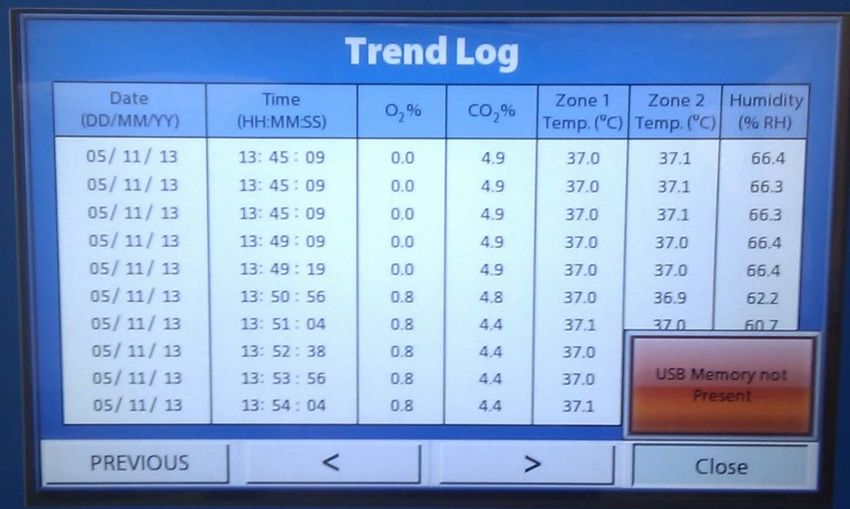
Removable front cover — allows easy access for cleaning or placing other analytical
instruments or microscopes into the workstation.
Three electrical power sockets inside the workstation.
Optional HEPA (High-efficiency particulate air) filtration system provides HEPA-filtered air
within the work area to protect research from airborne contaminants.
Optional external enhanced containment package provides added protection for user.
Easily Accommodates Your Analytical Tools
The SCI-tive Plus can easily accommodate a variety of analytical equipment. Please contact
Baker Ruskinn or your local distributor for a list of approved products. Products must be
suitably safety approved in the country of use.
Please read this manual carefully before using the SCI-tive Plus and familiarise yourself with all
aspects of using the workstation. The Baker Company (Baker) or Ruskinn Technology Ltd (Ruskinn)
does not accept responsibility for accidents to personnel or damage to the SCI-tive Plus
workstation resulting from incorrect use.
*Note. The use of the word Interlock in this manual is medical terminology, and refers to the
environmental working area between both chambers. It does not refer to the engineering safety
interlock switch mechanism.
UM-033 Version 3.0 Page 3 of 82 SCI-tive Plus User Manual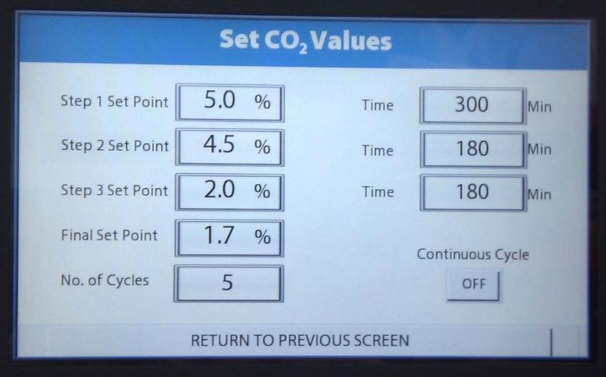
1.     OVERVIEW ................................................................................................................................................ 6
     1.1      SAFETY INSTRUCTIONS ......................................................................................................................................................... 6
     1.2      REGULATORY COMPLIANCE .................................................................................................................................................. 7
     1.3      SYMBOLS .............................................................................................................................................................................. 9
     1.4      SYSTEM OVERVIEW, INSTALLATION AND RELOCATION ......................................................................................................10
     1.5      WEIGHT AND DIMENSIONS .................................................................................................................................................10
     1.6      ENVIRONMENTAL OPERATING CONDITIONS......................................................................................................................10
     1.7      STORAGE TEMPERATURE ....................................................................................................................................................10

2.     GAS AND ELECTRICAL SUPPLY REQUIREMENTS ................................................................................. 12
     2.1      GAS SUPPLY REQUIREMENTS ..............................................................................................................................................12
     2.2      GAS REGULATOR REQUIREMENTS .......................................................................................................................................14
     2.3      ELECTRICAL SUPPLY REQUIREMENTS ..................................................................................................................................14
     2.4      VOLTAGE AND FREQUENCY REQUIREMENTS ......................................................................................................................14
     2.5      POWER CONSUMPTION ......................................................................................................................................................14
     2.6      POWERING THE WORKSTATION ..........................................................................................................................................14

3.     WORKSTATION OVERVIEW ................................................................................................................... 15
     3.1      FRONT VIEW ........................................................................................................................................................................15
     3.2      HUMIDIFIER END PANEL (LEFT HAND SIDE VIEW)..............................................................................................................16
     3.3      RIGHT HAND SIDE VIEW ......................................................................................................................................................17
     3.4      REAR VIEW ..........................................................................................................................................................................18
     3.5      INTERNAL CHAMBER ...........................................................................................................................................................19

4.     CONTROLLER OVERVIEW ...................................................................................................................... 22
     4.1      SCI-TIVE PLUS WORKSTATION CONTROL PANEL ..............................................................................................................22
     4.2      INITIAL POWER UP ..............................................................................................................................................................23
     4.3      INTERNAL LIGHTS................................................................................................................................................................24
     4.4      INTERNAL POWER SOCKETS ................................................................................................................................................25
     4.5      TEMPERATURE CONTROL ...................................................................................................................................................26
     4.6      HUMIDITY CONTROL OVERVIEW.........................................................................................................................................30
     4.7      ENVIRONMENTAL GAS COMPOSITION - ATMOSPHERE CONTROL ......................................................................................34
     4.8      SETTING UP A HYPOXIC CYCLE ...........................................................................................................................................37
     4.9      ANOXIC CONTROL ..............................................................................................................................................................42
     4.10     OXYGEN (O2) SENSOR CALIBRATION.................................................................................................................................43
     4.11     SETTING THE DATE AND TIME .............................................................................................................................................45
     4.12     TREND LOG .........................................................................................................................................................................46
     4.13     GAS USAGE, CHANGE TIMES AND STABILITY ......................................................................................................................50

5.     USING THE INTERLOCK .......................................................................................................................... 51
     5.1      INTERLOCK OVERVIEW.........................................................................................................................................................51
     5.2      OPENING THE INTERLOCK OUTER DOOR.............................................................................................................................52
     5.3      HAND ACCESS TO THE WORKSTATION CHAMBERS .............................................................................................................56
     5.4      WASTE PORT .......................................................................................................................................................................64

6.     CLEANING AND MAINTENANCE............................................................................................................ 65
     6.1      CLEANING THE WORKSTATION ...........................................................................................................................................65
     6.2      MAINTAINING THE WORKSTATION – END USER MAINTENANCE ........................................................................................68
     6.3      SERVICE REQUIREMENTS .....................................................................................................................................................75
     6.4      SPARE PARTS AND ACCESSORIES ........................................................................................................................................76

UM-033 Version 3.0                                                                 Page 4 of 82                                                  SCI-tive Plus User Manual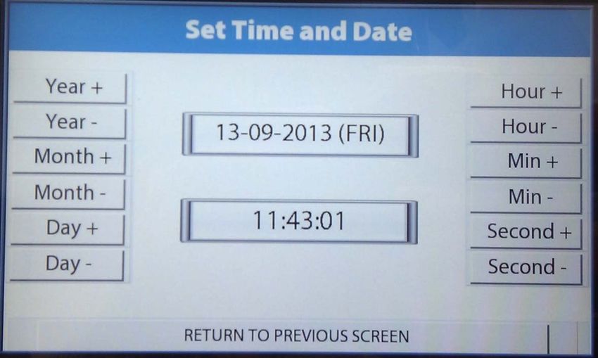
6.5      WORKSTATION MALFUNCTION...........................................................................................................................................77
     6.6      COMMON PROBLEMS AND SOLUTIONS ..............................................................................................................................77

7.     WARRANTY INFORMATION................................................................................................................... 80

8.     DISPOSAL INFORMATION ..................................................................................................................... 81

9.     CONTACT DETAILS ................................................................................................................................. 82

UM-033 Version 3.0                                                         Page 5 of 82                                            SCI-tive Plus User Manual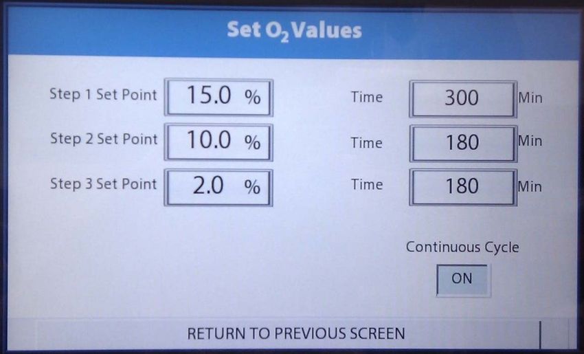
1. Overview
1.1 Safety Instructions
Baker and/or Ruskinn do not take any responsibility for damages caused by using the equipment
for other purposes than described in this user manual.
The mains appliance coupler and plug are the AC mains supply isolation device and must be
easily accessible when installed.
In case of emergency disconnect the SCI-tive Plus from the AC Mains Outlet.
Ensure that the connecting cable is not squeezed or bent when the unit is being installed or
moved.
All installation work and adjustments to the unit must be carried out by qualified personnel. Work
performed by persons with insufficient technical knowledge may adversely affect the
performance of the unit or cause physical injury or damage to the equipment.
All servicing and repairs must be carried out by a qualified customer service engineer. Only
genuine spare parts must be used.
In case of damage to the SCI-tive Plus disconnect the workstation from the mains outlet and
contact your local distributor.
All covers and lids must only to be removed by a qualified service engineer.
Nothing should be placed on the top of the workstation.
A power cord supplied with the workstation and should be used to connect to the mains outlet.
If a replacement is required it must be adequately rated for the application.
All cables and pipes should be routed to ensure that they do not pose a trip hazard.
Mains supply Voltage fluctuation must not exceed ±10% of the nominal Voltage.
Gas regulators must be used for each gas supply. A 2 stage regulator is recommended with a
maximum supply pressure of 4 Bar. Over pressure could damage the workstation.
Only the gases specified in this user manual may be used.
All gas bottles must be adequately secured before connection to the workstation.
The maximum power rating of the internal sockets must not be exceeded.
The end user is responsible for all materials and equipment places inside the workstation.
Before connecting any equipment to the internal mains sockets ensure that the equipment has
or is connected to a protective earth. If in doubt please contact the equipment manufacturer.
The workstation must not be operated at an ambient temperature over 30°C.
The cooling fan covers and cooling vents must not be covered or blocked.
The weight limit for the workstation internal floor is 30kg and must be evenly distributed.
The weight limit for the interlock tray is 5kg and must be evenly distributed.
There should be no naked flames close to the workstation.
The use of radioactive materials if strictly prohibited.
CAUTION: Asphyxiation Risk
The SCI-tive Plus uses Nitrogen (N2) and Carbon Dioxide (CO2) as part of normal use with the volume
released externally is inconsequential. In the event of a leak or malfunction this gas release may
become excessive. DO NOT OPERATE this unit in a SMALL ENCLOSURE such as a small room or walk-
in closet. An accidental release of Nitrogen or Carbon Dioxide could create an asphyxiating
atmosphere in a small space.
If the equipment is not use in a manor specified by the manufacture, the protection provided by the
equipment may be impaired.
Failure to adhere to these safety instructions could cause serious injury and will invalidate the
workstation warranty. Baker Ruskinn accepts no responsibility for any accident, injury or loss
caused by unsafe operation of the workstation.
UM-033 Version 3.0 Page 6 of 82 SCI-tive Plus User Manual
1.2     Regulatory compliance

           European Region

This product complies with the essential EEA requirements for Electrical Safety and
Electromagnetic compatibility as set out in the EMC directive 2004/108/EC and the Low
Voltage Directive 2006/95/EC and has been tested and found to comply in full with the
requirements of the following standards:

Electrical Safety:

EN 60601-1:2006 Medical electrical equipment - Part 1: General requirements for basic safety and
essential performance.

Electromagnetic Compatibility

EN 60601-1-2:2007 Medical electrical equipment - Part 1-2: General requirements for basic safety
and essential performance - Collateral standard: Electromagnetic compatibility - Requirements and
tests.

           WEEE:

This equipment must be disposed of in accordance with the Waste from Electrical and Electronic
Equipment (WEEE) Directive

This product must not be treated as household waste. Instead, it shall be handed over to an
appropriate collection point for the recycling of electrical and electronic equipment.

If in doubt, please return this equipment to Baker Ruskinn who will correctly dispose of it for you.
We strongly recommend that this product is returned to RTL at the end of its useful life.

UM-033 Version 3.0                         Page 7 of 82                   SCI-tive Plus User Manual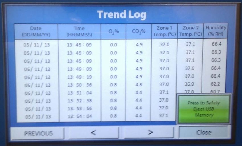
North America Region:

This product is UL 61010-1 Listed, and CSA C22.2 No. 61010-1 under file number E113911.

This equipment has been tested and found to comply with the limits for a Class A digital device,
pursuant to part 15 of the FCC Rules. These limits are designed to provide reasonable protection
against harmful interference when the equipment is operated in a commercial environment. This
equipment generates, uses, and can radiate radio frequency energy and, if not installed and used in
accordance with the instruction manual, may cause harmful interference to radio communications.
Operation of this equipment in a residential area is likely to cause harmful interference in which case
the user will be required to correct the interference at his own expense.

            Precautions
The SCI-tive Plus has been tested and approved to EN61010-1.This means that the SCI-tive Plus
meets or exceeds the requirements for general electrical laboratory equipment in terms of its levels
of emitted electromagnetic (EM) radiation and its susceptibility to electromagnetic radiation from
other devices. It should be noted that the SCI-tive Plus may be affected by high levels of stray EM
radiation from other electronic devices (even those which comply with relevant CISPR emission
standards) that are being used in close proximity to it.

WARNING: This system may cause radio interference or may disrupt the operation of nearby
equipment. It may be necessary to take mitigation measures, such as re-orienting or relocating the
equipment or shielding the location.

UM-033 Version 3.0                          Page 8 of 82                    SCI-tive Plus User Manual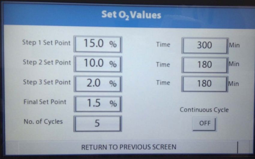
1.3    Symbols
Before using the SCI-tive Plus, please ensure that you are familiar with the symbols on the SCI-tive
Plus.

Figure 1: SCI-tive Plus symbols
  Symbol          Meaning

                  Refer to user manual.

                  Alternating current
       ~
       O          Off

        I         On

                  Functional Earth Connection

                  Protective Earth Connection

                  This product complies with the essential EEA requirements for Electrical Safety
                  and Electromagnetic compatibility as set out in the EMC directive
                  2004/108/EC and the Low Voltage Directive 2006/95/EC

                  Caution, do not remove covers. No end user serviceable parts behind covers.
                  Please refer to this manual in all cases where this symbol appears, in order to
                  find out the nature of the Potential Hazard and actions to be taken in order to
                  avoid the Hazard.

                  Warning, this equipment contains high voltage circuitry.

                  Contains material or substances that may be hazardous to human health.
                  Please refer to your local biohazardous material handling procedure for
                  further advice on the handling and disposal of these items.

                  InvivO2 contains hazardous components and must not be disposed of at a
                  household waste site. Instead it should be taken to the appropriate collection
                  point for the recycling of electrical and electronic equipment.

                  USB socket

                  Date of manufacture in format
                  YYYY MM

UM-033 Version 3.0                         Page 9 of 82                   SCI-tive Plus User Manual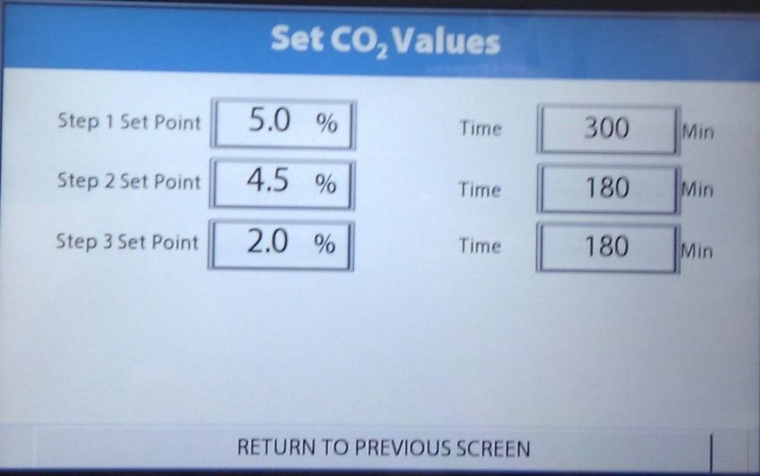
1.4 System Overview, Installation and relocation
The SCI-tive Plus Workstation provides hypoxic or anoxic environments with control of temperature
and humidity, to provide the optimum environment for cell biology incubation and
experimentation.
SCI-tive Plus should only be installed or relocated by a qualified engineer. To arrange installation or
relocation, please contact your local distributor.
The mains socket that forms connection to the SCI-tive Plus, is not to be obstructed by
SCI-tive Plus or any other equipment, and must be accessible in case of emergency. In
case of emergency, disconnect the SCI-tive Plus from the AC mains outlet.
1.5 Weight and dimensions
The SCI-tive Plus workstation weighs approximately 230kg. Figure 2 lists the dimensions of the SCI-
tive Plus workstation;
Figure 2: SCI-tive Plus workstation dimensions
External width 1530mm
External height 1897-1949mm
External depth 985 mm
Workstation chamber internal width 1020mm
Workstation chamber internal height 808 mm
Workstation chamber internal depth 760 mm
Interlock internal width 270 mm
Interlock internal height 210 mm
Interlock internal depth 200 mm
Interlock outer door clear opening width 262 mm
Interlock outer door clear opening height 210 mm
Interlock inner doors clear opening width 232 mm
Interlock inner doors clear opening height 201 mm
1.6 Environmental Operating Conditions
The SCI-tive Plus Workstation should only be operated under the following environmental
conditions:
Temperature – Between 150C and 300C
Humidity – Between ambient and 90% RH, Non-Condensing
1.7 Storage Temperature
When not in use, the SCI-tive Plus Workstation must only be stored under the following
environmental conditions:
Temperature – Between 00C and 300C
UM-033 Version 3.0 Page 10 of 82 SCI-tive Plus User ManualStorage outside of this range may damage the workstation. UM-033 Version 3.0 Page 11 of 82 SCI-tive Plus User Manual
2. Gas and electrical supply requirements

2.1     Gas supply requirements
The Gas supplies are connected to the back of the SCI-tive Plus Workstation as shown in Figure 3. A
full description of the rear of the unit is provided in Section 3.4. Please refer to Figure 1 for Hazard
symbol explanations.
                                Figure 3: Gas and electrical connections

Figure 4 lists the gasses required for operation of the workstation with Figure 5 detailing additional
gases that are required for specific operating modes;
Figure 4: SCI-tive Plus gas requirements
        Gas                       Symbol           Specification             Hose Diameter
        Nitrogen                  N2               Oxygen Free               ID: 8mm
                                                   (Industrial or medical)   OD: 13.5mm
        Carbon Dioxide            CO2              100%                      ID: 8mm
                                                   (Industrial or medical)   OD: 13.5mm
        Compressed Air            N/A              Compressed                ID: 8mm
                                                   (Industrial or medical)   OD: 13.5mm
Figure 5: SCI-tive Plus gas requirements for specific conditions
 Gas             Symbol     Specification            Replaces Use                    Hose
                                                                                     Diameter
 Hydrogen in H2/N2         Recommended Max         N/A        For anoxic             ID: 6.3mm
 Nitrogen*                 5.5% Hydrogen in                   mode                   OD: 11.5mm
 (In addition              Nitrogen
 to Figure 4               (Industrial or
 gases)                    medical)
 25%           O2/N2       Maximum of 25%          Air        For maintaining ID: 8mm
 Oxygen in                 Oxygen in Nitrogen                 oxygen at levels OD: 13.5mm
 Nitrogen                  (Industrial or                     higher than
 (Replaces                 medical)                           17%
 Air in Figure
 4)
NOTE: Only gasses listed in Figure 4 and Figure 5 may be used with the workstation. The use of any
other gasses will invalidate the warranty and may cause serious injury.

UM-033 Version 3.0                          Page 12 of 82                    SCI-tive Plus User Manual
* - Recommended Hydrogen concentrations are compliant to BS EN ISO 10165:2010 (Classification of Flammable Gasses). The use of Hydrogen concentrations up to a maximum of 10% in Nitrogen (N2) is the responsibility of the user and must be assessed by the user in accordance to local safety regulations at the installation location. UM-033 Version 3.0 Page 13 of 82 SCI-tive Plus User Manual
2.2 Gas regulator requirements
Gas regulators must be used with all gas supplies to the workstation. A 2 stage regulator must be
used for each bottled gas supply. Regulators should be available from your local gas supplier. Baker
Ruskinn does not supply gas regulators.
The gas regulator should provide a minimum supply pressure of 3 bar gauge. The maximum supply
pressure permissible is 4 bar gauge. A supply pressure greater than this may damage internal
components of the workstation and will invalidate the warranty.
2.3 Electrical supply requirements
The workstation must be connected to a mains power supply. A power cord is supplied to connect
the workstation to the mains supply as shown in Figure 3. Only the power cord supplied should be
used to connect the workstation to the mains supply. The workstation must be connected to a
protective earth.
The mains socket the SCI-tive Plus is connected to should not be obstructed by SCI-
tive Plus or any other equipment, and must be accessible in case of emergency.
2.4 Voltage and frequency requirements
To ensure safe operation of the workstation, it must be connected to a supply of the correct voltage
and frequency as stated on the rating label shown at the rear of the unit shown in Figure 12. The
mains supply voltage fluctuations must not exceed +/- 10% of the nominal mains voltage. The input
voltage and frequency for SCI-tive Plus workstations are;
Input voltage and frequency variants:
230 Volts AC, 50Hz
110 Volts AC, 50Hz.
110 Volts AC, 60Hz.
2.5 Power consumption
The power consumption for the SCI-tive Plus is shown below in Figure 6.
Figure 6: Power Consumption
230V Version 110V Version
Nominal Current 4A 8A
Maximum Current 6A 12.5A
Power, 230V 1260W 1260W
2.6 Powering the workstation
The SCI-tive Plus is fitted with an Un-Switched Mains Inlet. To isolate the equipment from the mains
supply, disconnect the mains plug from the AC Outlet.
UM-033 Version 3.0 Page 14 of 82 SCI-tive Plus User Manual3. Workstation overview 3.1 Front view The SCI-tive Plus is shown below in Figure 7. The chamber is controlled via the central touch screen controller. A USB port is featured below the controller, together with a blue LED. A USB flash drive is provided with the Workstation and has to be present at all times for data logging. The blue LED, when lit, indicates mains power is present to the SCI-tive Plus workstation. The Interlock door is situated below the Workstation control screen. Figure 7: SCI-tive Plus Front View Note: Only memory storage devices are to be connected to the USB port(s). Only USB storage devices that do not require an external power supply are to be used with the workstation. UM-033 Version 3.0 Page 15 of 82 SCI-tive Plus User Manual
3.2     Humidifier End Panel (Left hand side view)
Figure 8 shows the humidity end panel of the workstation. Figure 9 shows the RCCB for the
workstation, refer to Section 6.6 for advice on steps to follow if the RCCB trips. Please refer to Figure
1 for Hazard symbol explanations.

                     Figure 8: SCI-tive Plus Humidifier End Panel Left
                                                                                Figure 9: RCCB for the
                                                                                workstation

                                                                         1

                                                                         2

          6
                                                                         3
          7

                                                                         4

                                                                         5

                             1.   Workstation Residual Current Circuit Breaker (RCCB)
                             2.   Humidity Port Vent (Do not obstruct)
                             3.   Fan vent (Do not obstruct)
                             4.   Exhaust vent (Do not obstruct)
                             5.   Auxiliary Access Panel and Vacuum Pump line
                             6.   Oil Level tank viewing area (Secondary Pressure Relief)
                             7.   Humidity System Water tank viewing area
        Hazard labels: WARNING THIS EQUIPMENT MUST BE EARTHED

                         CAUTION: Risk of Electrical Shock. Do Not Open

UM-033 Version 3.0                           Page 16 of 82                    SCI-tive Plus User Manual
3.3 Right hand side view
Figure 10 shows the right hand side of the SCI-tive Plus workstation. Please refer to Figure 1 for
Hazard symbol explanations.
Figure 10: SCI-tive Plus Plus Right hand side
Hazard labels: WARNING THIS EQUIPMENT MUST BE EARTHED
CAUTION: Risk of Electrical Shock. Do Not Open
Note: A blue drain pipe for the condensate module can be found below the right hand side. Locate
a beaker or flask below the drain pipe, and regularly check the fill level of the beaker. The
condensate module is a result of the drying process for the sample of the internal Atmosphere for
gas control.
UM-033 Version 3.0 Page 17 of 82 SCI-tive Plus User Manual3.4 Rear View
Figure 11 and Figure 12 show the rear of the SCI-tive Plus workstation;
Figure 11: SCI-tive Plus Plus Rear view
2
1
3
1. Secondary Pressure relief system vent DO NOT OBSTRUCT
2. Rating Label
3. Rear Electrical and Gas connections (see figure below)
Figure 12: Rear electrical connections
3
1
4
5
2
6
1. Air vent. DO NOT OBSTRUCT
2. Gas inlets. (Maximum Pressure Must Not Exceed 5bar)
3. Ethernet port (For service personnel only).
4. Primary ground.
5. Fuse Points 8A F1 F2.
6. Mains inlet.
UM-033 Version 3.0 Page 18 of 82 SCI-tive Plus User Manual3.5 Internal Chamber
The SCI-tive Plus Chamber, is equipped with:
Two Internal lights (Left hand side and Right hand side).
Three electrical points ( Figure 15).
Water tank access point for filling (Figure 13). Refer to Section 4.6.4 for details of filling water
tank.
Temperature and Humidity sensors.
Interlock internal door.
Interlock inner door control button and indicator (Figure 14) Refer to Section 5.2.1 for
operation.
The control and operation for the above features are achieved via the touch screen controller.
Figure 13: Water Tank fill port Figure 14: Interlock internal door release
2
1
1. Water Tank Acces point for filling 2. Interlock internal door release button
Figure 15: European Internal Power sockets Figure 16: UK Internal Power Sockets
Figure 17: US Internal Power Sockets
Note: Other socket variations are available
UM-033 Version 3.0 Page 19 of 82 SCI-tive Plus User ManualAdditional features found on the side wall of the chamber, include:
Universal Multi gland port
Cable Gland port
Vacuum Line port
Figure 18: Internal view of multi-port, vacuum port and cable gland
1
2
3
1. Universal multi gland port
2. Vacuum line port
3. Cable gland port
Figure 18 shows the internal chamber outside wall showing the Universal multi-port gland, vacuum
line port and cable gland port.
Universal multi-port
Figure 19: Universal multi-port
The Universal multi-port cable gland is used to allow cables to enter the workstation chamber
without affecting the internal environment of the workstation chamber. The Universal cable gland
provides a diameter of 50mm for passing through larger cables and connectors.
UM-033 Version 3.0 Page 20 of 82 SCI-tive Plus User ManualVacuum port
The vacuum port is used to remove liquids from the workstation chamber, for example excess media
from Petri dishes. The vacuum port is located on the left hand side of the workstation.
To use the vacuum port;
Connect the vacuum source to the external part of the vacuum port by pushing a tube from
the vacuum source onto the vacuum port hose connection.
Insert the internal vacuum hose into the internal section of the vacuum port. Figure 20
shows the internal part of the vacuum port;
Figure 20: Internal view of vacuum port
When the vacuum is no longer required, remove the internal vacuum hose from the vacuum
port by pressing the top of the metal part of the internal section of the vacuum port and
pulling the vacuum hose. The hose should release from the vacuum port, sealing the
vacuum port.
Remove the vacuum source from the outside of the vacuum port.
Cable gland
The cable gland is used to allow cables to enter the workstation chamber without affecting the
internal environment of the workstation chamber. The cable gland is suitable for cables of diameter
3.5mm to 7mm. The cable gland is located on the left hand side of the workstation
Figure 21: Cable gland
To use the cable gland;
Turn the grey collar anti-clockwise (counter-clockwise) to loosen the cable gland.
Remove the red plug.
Push the cable through the cable gland.
Tighten the grey collar by turning clockwise until tight. Do not over tighten the cable gland.
UM-033 Version 3.0 Page 21 of 82 SCI-tive Plus User Manual4. Controller Overview
4.1 SCI-tive Plus Workstation Control Panel
The SCI-tive Plus Workstation is equipped with a touch screen control panel.
Figure 22: SCI-tive Plus Workstation controller
1
2
3
1. Chamber Controller
2. Power indicator for the SCI-tive Plus Workstation
3. Chamber USB Port
UM-033 Version 3.0 Page 22 of 82 SCI-tive Plus User Manual4.2 Initial Power Up
When the SCI-tive Plus Workstation is initially powered up the first screen displayed is as shown
below in Figure 23. This is quickly followed by the Main Control Screen Top menu as shown in
Figure 24. It is recommended that the user checks both the water tank and oil tank levels before
operation.
Figure 23: Initial Power Up Screen
Figure 24: Main Control Screen Menu
UM-033 Version 3.0 Page 23 of 82 SCI-tive Plus User Manual4.3 Internal Lights The internal Lights can be set from the menu on the left hand side of the “Gas Control Settings”, “Hypoxic Cycle Settings” or “Anoxic Settings” screens, which are accessed from the Main Control Screen shown in Figure 24. Figure 25: Atmosphere Control Screen Light settings The chamber is equipped with two internal lights (left and right). These are displayed by a light bulb on the Left Hand Side menu, one for the left light, and one for the right light. To activate the left light, touch the Left Light Bulb icon on the screen, and the button will change from displaying a red “OFF” indicator to a green “ON” indicator on the screen, when the light is on. Figure 26: Light Bulb switch on and off To switch off each light, touch the relevant left or right light bulb button, and the button will turn from displaying a green “ON” to red “OFF” and the internal light will be switched off. UM-033 Version 3.0 Page 24 of 82 SCI-tive Plus User Manual
4.4     Internal Power sockets
The chamber has 3 internal power sockets, located on the back wall of the workstation chamber as
shown in Figure 15.

The Internal power sockets can be set from the menu on the left hand side of the “Gas Control
Settings”, “Hypoxic Cycle Settings” or “Anoxic Settings” screens, which are accessed from the
Main Control Screen shown in Figure 24.

To activate the internal power sockets, located at the back wall of the chamber Figure 15, press the
power socket button as shown in Figure 27. The button will change from displaying a red “OFF”
indicator to a green “ON” indicator on the screen, when the internal power sockets are on.

Figure 27: Internal power socket switch

To switch the internal sockets off, press the power socket button and the button will turn from
displaying a green “ON” to Red “OFF” and the internal power sockets will be switched off.

          The Maximum Power rating of the chamber is 460W.

Note: The Maximum Power Rating is the combined total of the three internal mains sockets and the
maximum power should not be exceeded. Note also that any devices placed inside the workstation
should be checked for compatibility with the temperature and humidity conditions within the
workstation chamber. Baker Ruskinn accepts no liability for items damaged inside the workstation
chamber that are not suitable for the conditions.

UM-033 Version 3.0                        Page 25 of 82                   SCI-tive Plus User Manual
4.5 Temperature Control The chamber’s temperature can be set from the control screen. The SCI-tive Plus workstation chambers Temperature Control is set ON by default at power up, and the temperature in the chamber is set to 37oC by default. From the main menu control screen ( Figure 24), select the first button “Gas Control Settings”. When selected, the Atmosphere Control Screen will be displayed as shown in Figure 29. The Temperature Control can be set from the menu on the left hand side of the “Gas Control Settings”, “Hypoxic Cycle Settings” or “Anoxic Settings” screens, which are accessed from the Main Control Screen shown in Figure 24. To switch the temperature control off, in the chamber, press the temperature control button, and the button will turn from displaying a green “ON” to Red “OFF”. Figure 28: Temperature Control Button The temperature can be controlled between ambient + 5oC and 45oC. To change the temperature, touch the Temperature Set Point box shown in Figure 29, and a numeric pad will appear to allow a different value to be entered, as shown in Figure 30. The resolution of the temperature input setting is 0.1oC. The Temperature Set Point box sets the temperature for each zone of the chamber and the interlock. NOTE: The interlock temperature follows the temperature that has been set in the Temperature Set Point box. The interlock temperature cannot be set independently. The Zone 1 value displays the temperature within the chamber. These cannot be set by the user. UM-033 Version 3.0 Page 26 of 82 SCI-tive Plus User Manual
Figure 29: Atmosphere Control Screen

                              Figure 30: Temperature set screen

UM-033 Version 3.0                      Page 27 of 82             SCI-tive Plus User Manual
Temperature alarms The chamber has an alarm function built into the temperature controller. An audible alarm will sound if the temperature increases or decreases +/- 1.0oC of the temperature setting. An alarm screen will appear as shown in Figure 31, and a “Temperature Alarm Present” message will appear on the main Atmosphere Control Screen shown in Figure 32. Figure 31: Temperature Alarms The alarm is turned off when the temperature returns to within +/- 1.0oC of the temperature setting. The user can acknowledge the alarm, using the “Acknowledge” button on the alarm screen in Figure 31 which will disable the audible alarm, however the alarm is not cleared until the temperature returns to within +/- 1.0oC of the temperature setting. If the temperature alarm is acknowledge and the temperature control system is unable to achieve the Temperature Set Point after twenty minutes the alarm will reactivate. If the temperature control is turned off from the main menu the temperature alarms are also disabled. UM-033 Version 3.0 Page 28 of 82 SCI-tive Plus User Manual
Figure 32: Temperature Alarm Present

The “Temperature Alarm Present” message is displayed on the main Atmosphere Control screen
as shown in Figure 32.

The location of the temperature alarm is indicated by each of the Zone 1, Zone 2, Interlock words
becoming red on the main screen. This is shown above in Figure 32, indicating that there is a
temperature alarm present in each of the zones of the relevant chamber and the Interlock.

When the temperature adjusts to within +/- 1.0oC of the temperature setting, the temperature alarm
clears.

UM-033 Version 3.0                        Page 29 of 82                 SCI-tive Plus User Manual
4.6     Humidity control Overview
The SCI-tive Plus workstation has a humidity control function in the chamber. The humidity can be
controlled between ambient and 85% relative humidity.

Note that at high humidity levels (greater than 70% relative humidity), condensation may form on
the inside of the front screen of the workstation. This is due to the temperature difference between
the inside of the workstation and the room it is located. To minimize the chance of condensation
forming, it is recommended that the workstation is not located by air conditioning vents or
windows.

The humidifier system uses a water tank to provide humidity for the workstation. Water is vaporised
and is injected into the workstation chamber to increase humidity when required. If the humidity is
too high, water vapour is condensed and returns to the water tank. The humidifier system is disabled
if the water level is too low. If the water level exceeds the maximum level viewed on the side panel
water tank, shown in Figure 8, then water is to be removed from the tank.

           Humidity control
The humidity control can be activated from the menu on the left hand side of the “Gas Control
Settings”, “Hypoxic Cycle Settings” or “Anoxic Settings” screens, which are accessed from the
Main Control Screen shown in Figure 24.

The Humidity settings are achieved via a % setting from the “Atmosphere Control Screen”.

Before activating the humidity system, the user should check:

        The water level is above the minimum level in the water tank as indicated on the end panel
        of the chamber as shown in Figure 8.

The Humidity control button is activated by pressing the rain and umbrella button as shown below.

If the humidity system is not required it can be disabled / turned off by pressing the button to OFF.

Figure 33: Humidity Control Button

The % relative humidity can be set by entering a % value into the (% RH) Set Point box from the
“Atmosphere Control Screen”. The % relative humidity can only be set when the humidity system
is on and the humidity button indicates a green ON.

UM-033 Version 3.0                         Page 30 of 82                   SCI-tive Plus User Manual
Humidifier Alarms To ensure the humidifier systems function correctly, the humidifier tanks must be filled to the correct level as indicated on the end panel of the chamber as shown in Figure 8.When the workstation is installed and powered up, a green information message will appear for 1 minute on the screen to show the level is ok as shown in Figure 34. This information message will also appear after the humidifier water tank is filled to the maximum level. Figure 34: Humidity System water ok If the humidifier water level is too low, a Water Low Alarm will be displayed as shown in Figure 35, Figure 36 and the humidity system is disabled. The Water Low Alarm requires immediate attention to allow operation of the humidity system to continue. The user needs to re-fill the humidity water tank as described in Section 4.6.4, until the alarm is cleared. The Water Low Alarm can be acknowledge but the humidity system will remain disabled until the water tank is filled as shown by the message on the control screen Figure 35. Note: The humidity button will stay ON during this time that the system is disabled. The Water Low Alarm will repeat each hour, until the water tank is filled or the humidity system is switched off. When the tank is filled to the maximum level as shown by the indicators on the side of the water tank, the information message will be displayed for 1 minute as shown in Figure 34, to show that the level is ok. If the water tank is filled to minimum level, the alarm will clear, the humidity system will activate, but the message in Figure 34 does not appear. UM-033 Version 3.0 Page 31 of 82 SCI-tive Plus User Manual
Figure 35: Humidity System Water level Low

Figure 36: Water Low Alarm

          Humidifier water consumption
The humidity system injects water into the workstation chamber as a vapour. This consumes water
from the humidifier tank. As the workstation is used, some humidity is lost via the interlock, the
waste port, the exhaust valves and the Ezee-Sleeves. The water consumption creates the
requirement for the water tank to be refilled.

UM-033 Version 3.0                        Page 32 of 82                 SCI-tive Plus User Manual
Refilling the humidifier tank
The water tank is filled from inside the chamber, by means of a small water bottle with a pipette end,
as shown In Figure 37. Ionised sterile water must be used to avoid contamination.
Figure 37: Refilling the water tank
Figure 38: Water tank internal level
indicators
A water bottle with a pipette end is to be passed into the chamber through the interlock and purge
process.
Once the bottle is inside the chamber, the user accesses the left most glove post, picks up the bottle
of ionised sterile water and inserts water into the tank at the side of the chamber. Fill the water
according to the physical MAX and MIN water level indicators on the tank.
The alarm will stop when there is sufficient water in the water tank.
Check the humidity button is ON and there are no other alarms or messages displayed on the
Atmosphere Control screen.
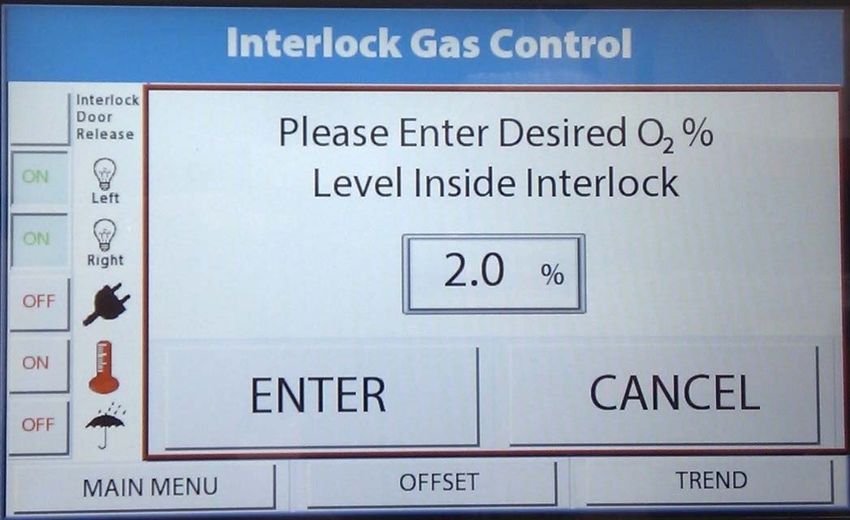
UM-033 Version 3.0 Page 33 of 82 SCI-tive Plus User Manual4.7 Environmental gas composition - Atmosphere control
To set up Gas control for the chambers the user should select “Gas Control Settings” from the
main menu. Once selected the Atmosphere Control screen as shown in Figure 39 is displayed.
Gas control overview
Figure 39: Gas controller menu screen- Atmosphere Control
The O2 Set point and CO2 Set point can be set using the Atmosphere Control screen as shown above.
O2 Set point: This is the required oxygen concentration. The O2 set point can be set between 0.1%
and 20.9% in this menu.
For oxygen concentrations of 0.0%, use the “Anoxic Control Menu” option as described in Section
4.9.
For oxygen concentrations greater than 17.0% a combination 75% Nitrogen and 25% Oxygen
supply will need to be connected to the O2 connection at the rear of the workstation as shown in
Section 3.4.A red warning screen will appear if this is set above 17.0% as shown in Figure 41.
CO2 Set point: This is the required carbon dioxide concentration. The CO2 set point can be set
between 0.1% and 30.0%.
O2 Value: This is the actual oxygen concentration.
CO2 Value: This is the actual carbon dioxide concentration.
The Trend button provides the Trend log for the parameter. Please refer to Section 4.12 for further
information on the event log.
UM-033 Version 3.0 Page 34 of 82 SCI-tive Plus User ManualAtmosphere Control Alarms Individual alarms are displayed on the Control Screen for low pressure on the O2, CO2 and N2 If gas pressure alarms are present check the incoming gas supplies at the rear of the workstation. Figure 40: Atmosphere Control Alarms Screen Figure 41: Change Gas Warning Alarm This alarm occurs when the O2 set point has been set above 17.5% requiring the compressed air cylinder to be changed. UM-033 Version 3.0 Page 35 of 82 SCI-tive Plus User Manual
The user can acknowledge the alarm, using the “Acknowledge” button on the alarm screen.

Figure 42: Failure to reach Set Point Alarm

This alarm occurs when the internal control time limit to reach Set point has been exceed and the
cycle is aborted. This function prevents excessive gas usage. It is recommended to adjust the set
point and re-start the cycle. If this alarm occurs repeatedly see trouble shooting in Section 6.6.1.

Figure 43: Low Pressure Time Limit Alarm

The low pressure time limit alarm occurs when the chamber has been un-able to reach the
required level over a set time period (15 minutes default). This could be due to glove ports being
left off, leakage, or the incoming gas supply needing to be changed.

UM-033 Version 3.0                            Page 36 of 82                SCI-tive Plus User Manual
4.8     Setting up a Hypoxic cycle
From the main control screen menu, select the Hypoxic Cycle Settings button. The user can
choose to run a Continuous Cycle or a Non Continuous Cycle.

Figure 44: Main Control Menu - Hypoxic Cycle Settings

Figure 45: Hypoxic Cycle Menu

Press the O2 VALUES button to enter O2 set up screen and the CO2 VALUES button to enter the
CO2screen. The Cycles will be shown on the main hypoxic cycle screen shown in Figure 45.

The TREND button provides the Trend log for the parameter. Please refer to Section 4.12 for further
information on the event log.

UM-033 Version 3.0                        Page 37 of 82                  SCI-tive Plus User Manual
Figure 46: Set 02 Values Non continuous Cycle
Setting a Non Continuous Cycle
Set the cycle by setting each of the Steps and the required time for each step, by entering the
required values.
Step 1 Set point 1: This is the oxygen concentration for the first phase of the hypoxic cycle. Time:
This is the time span of the first phase of the hypoxic cycle in minutes.
Step 2 Set point 2. This is the oxygen concentration for the second phase of the hypoxic cycle. Time:
This is the time span of the second phase of the hypoxic cycle in minutes.
Step 3 set point 3. This is the oxygen concentration for the third phase of the hypoxic cycle. Time:
This is the time span of the third phase of the hypoxic cycle in minutes.
Final Set Point. This is the oxygen concentration for the final phase of the hypoxic cycle. The final
phase will operate until the cycle is aborted by the user.
No. of Cycles. This allows the number of cycles to be set. This can be set on either O2 or CO2 screens,
however the number of cycles is to be set the same. This is the last value to be entered on either the
O2 or CO2 screen.
Select “Set point 1” and enter the required value (between 0.1% and 21.0%) and time in minutes.
Please refer to Section 4.7.1 for setting higher than 17.0%.
Select “Set point 2” and enter the required value (between 0.1% and 21.0%) and time in minutes.
Select “Set point 3” and enter the required value (between 0.1% and 21.0%) and time in minutes.
Select “Final” and enter the required value (between 0.1% and 21.0%) and time in minutes.
Select “No. of Cycle” to set the number of cycles required.
Return to previous screen and select CO2 Values button.
UM-033 Version 3.0 Page 38 of 82 SCI-tive Plus User ManualFigure 47: CO2 Values for Non-Continuous Hypoxic Cycle Step 1 Set point 1: This is the Carbon Dioxide concentration for the first phase of the hypoxic cycle. Time: This is the time span of the first phase of the hypoxic cycle in minutes Step 2 Set point 2. This is the Carbon Dioxide concentration for the second phase of the hypoxic cycle. Time: This is the time span of the second phase of the hypoxic cycle in minutes Step 3 set point 3. This is the Carbon Dioxide concentration for the third phase of the hypoxic cycle. Time: This is the time span of the third phase of the hypoxic cycle in minutes Final Set Point. This is the Carbon Dioxide concentration for the final phase of the hypoxic cycle. The final phase will operate until the cycle is aborted by the user. No. of Cycles. This allows the number of cycles to be set. Select “Set point 1” and enter the required value (between 0.1% and 30.0%) and time in minutes. Select “Set point 2” and enter the required value (between 0.1% and 30.0%) and time in minutes. Select “Set point 3” and enter the required value (between 0.1% and 30.0%) and time in minutes. Select “Final” and enter the required value (between 0.1% and 30.0%) and time in minutes. Return to previous screen and press START. The hypoxic cycle will now start and the number of cycles remaining will be displayed on the hypoxic cycle screen as shown in Figure 45. UM-033 Version 3.0 Page 39 of 82 SCI-tive Plus User Manual
Setting a Continuous Cycle

To set a continuous cycle, press the Continuous Cycle button on the O2 screen and a three Step
cycle can be set with the respective times for each step.

Figure 48: Set O2 Values for Continuous Hypoxic Cycle

The Continuous Cycle will operate until the cycle is aborted by the user.

The Cycle is aborted by pressing the RETURN TO PREVIOUS SCREEN button.

Figure 49: Set CO2 Values for Continuous Hypoxic Cycle

UM-033 Version 3.0                         Page 40 of 82                    SCI-tive Plus User Manual
Hypoxic Control Alarms
The “HYPOXIC CONTROL” screen will display both Humidity System and Temperature Alarm
messages in Red text on the screen.

Figure 50: Hypoxic Control Alarms

UM-033 Version 3.0                    Page 41 of 82               SCI-tive Plus User Manual
4.9      Anoxic Control
The Anoxic Control menu allows the workstation to be run in anoxic mode (0.0% oxygen). To run in
anoxic mode, Hydrogen gas in Nitrogen is required. The maximum permissible concentration is
5.5% Hydrogen in Nitrogen.

In addition to this, two small catalyst sachets are required per chamber. The catalyst combines
Hydrogen and Oxygen to form water, thereby removing all Oxygen from the inside of the chamber.

Note that there is no oxygen control in this operating mode.

            Overview
To enter the anoxic mode, select “Anoxic Settings” from the main menu. The Anoxic Control screen
will then be displayed as shown in Figure 51.

Figure 51: Anoxic control screen

      O2 Value: This is the actual oxygen concentration in the workstation chamber.

      CO2 Set Point: CO2 % can be set.

      CO2 Value: This is the actual CO2 concentration in the workstation chamber.

          Anoxic Menu
The Anoxic Menu is password protected and for use by service personnel only.

          Trend Screen
The Trend button provides the Trend log for the parameters. Please refer to Section 4.12 for further
information on the Trend log.

UM-033 Version 3.0                          Page 42 of 82                  SCI-tive Plus User Manual
4.10 Oxygen (O2) Sensor Calibration
Overview
To ensure the correct function of the gas mixer, the oxygen sensor must be calibrated. The auto
calibration function of the gas mixer allows the oxygen sensor to be calibrated without destabilising
the environment in the workstation chamber. Baker Ruskinn recommends that the oxygen sensor is
calibrated on a monthly basis using the O2 Sensor calibration and replaced annually by a qualified
service engineer.
Screen layout
To enter the oxygen sensor auto calibration screen, select “O2 Sensor Calibration” from the main
menu. Figure 52 shows the oxygen sensor calibration screen;
Figure 52: Oxygen sensor calibration screen
Start Calibration. This starts the oxygen sensor automatic calibration.
Time Remaining. This gives the time remaining in seconds of the oxygen sensor automatic
calibration.
Last Calibration. This gives the date and time of the last oxygen sensor auto calibration.
Change Timers. This opens the service engineer screen, which is password protected. This
function is included for the use of qualified service engineers only. If the password screen is
entered accidentally press the return button on the password screen.
Previous. Press to return to the main menu via the return to main menu screen
UM-033 Version 3.0 Page 43 of 82 SCI-tive Plus User ManualCalibrating the oxygen sensor
To calibrate the oxygen sensor;
Enter the oxygen sensor auto calibration screen by selecting “Oxygen Calibration” from
the main menu.
Press “Start Calibration”. The time remaining counter will then begin.
Once the calibration has finished, the calibration result will be displayed.
Note: If the oxygen sensor fails calibration, it must be replaced.
It is recommended to replacement the sensor once a year.
For oxygen sensor replacement, please contact your local distributor.
UM-033 Version 3.0 Page 44 of 82 SCI-tive Plus User Manual4.11 Setting the date and time The date and time are set by the installer and are required for the Trend log. To set the date and time, select “Other settings” from the main menu and then press the SET DATE/TIME button as shown in Figure 53. Figure 53: Settings / Help Screen The date and time screen will be displayed as shown in Figure 54. Figure 54: Set Time and Date Screen Use the appropriate button to adjust the Day / Month / Year / Hour / Min / Second settings. Press “RETURN TO PREVIOUS SCREEN” button to return to the previous screens. UM-033 Version 3.0 Page 45 of 82 SCI-tive Plus User Manual
4.12    Trend log
The Trend log provides a historical record of the environmental conditions within the workstation.
The Trend log stores all data for the chamber when there is a USB device connected. Data is recorded
at 1 minute intervals.

           On Screen Trend log
The on screen Trend log shows the latest 1 hour of data (60 data entries).

Figure 55: Onscreen Event Log

Note: Upon entering the event log, the earliest recorded data will be displayed. A 60 minute window
can be scrolled through on the control screen. To view data over 60 minutes, the USB is to be
removed and connected to a computer. The USB can capture many years of data.

Note: When the USB is removed from the workstation, there will be no data logging for the length
of time that the USB is removed.

To safely remove the USB follow the next section.

           Removing the USB
The Trend log is continually downloaded to a USB. The chamber’s USB must be present at all times
of operation.

The USB can be removed by pressing the “USB Status” button (and if a USB is present), the following
screen will be displayed.

UM-033 Version 3.0                         Page 46 of 82                     SCI-tive Plus User Manual
Figure 56: Trend Log USB Removal The Green “Press to Safely Eject USB Memory” button should be pressed to safely remove the USB stick. Wait until the red “USB Memory removed” message to appear as shown in Figure 57 then remove the USB. Figure 57: Trend Log USB not present When the USB has been removed the following alarm screen is displayed. As shown below in Figure 58. UM-033 Version 3.0 Page 47 of 82 SCI-tive Plus User Manual
Figure 58: USB Memory Device removed alarm

The Trend Log screen also shows a red warning box with a message that the USB Memory is not
present.

UM-033 Version 3.0                     Page 48 of 82               SCI-tive Plus User Manual
Trend log on the USB device
The Trend log is continually downloaded to a USB and can be uploaded to a PC to be analysed. Note
that the USB must be formatted in the FAT32 data format. A Baker Ruskinn USB is provided with the
workstation, pre-formatted in FAT32 format. It is recommended that only the Baker Ruskinn USB
should be used for downloading the trend log. Note that only devices that insert directly into the
USB ports should be used. Devices attached via a cable should not be used.
Figure 59: Trend Log
The Trend log gives the following data;
Date.
Time.
Oxygen concentration present value (O2 PV).
Oxygen concentration set point (OPSP).
Carbon Dioxide concentration present value (CO2 PV).
Carbon Dioxide concentration set point (CO2 PSP).
Oxygen Deadband (O2 DB).
Carbon Dioxide Deadband (CO2 DB).
Oxygen Deadband Counter (O2 Count).
Carbon Dioxide Deadband Counter (CO2 Count).
Temperature System Set Point (Temp SP).
Zone1 Temperature Present Value (Z1 Temp PV).
Interlock Temperature Present Value (Int Temp PV).
Humidity Set Point (Humidity SP).
Humidity Present Value (Humidity PV).
Pressure Switch Counter (PS).
Note: The column PS refers to the pressure switch which is provided for the use of service engineers.
Pressure switch operation. This is the time in minutes since the last operation of the pressure switch.
The pressure switch operates when the pressure in the workstation chamber falls below a set level.
Nitrogen is injected into the workstation to increase the pressure, to maintain a positive internal
pressure.
Note: “Deadband” is the control limit around the target. In this limit gas will not be injected. E.g. For
a deadband of 0.2 around a 5% target, gas will not be injected if the sensor reads anywhere between
4.8% and 5.2%.
UM-033 Version 3.0 Page 49 of 82 SCI-tive Plus User ManualYou can also read