AltSource Electric thermal mass boiler - Thermo 2000
←
→
Page content transcription
If your browser does not render page correctly, please read the page content below
AltSource
Electric thermal mass boiler
     Power capacity : 4.5 kW to 29 kW :
     120V- 208/240V (single phase)

 INSTALLATION, USE AND CARE MANUAL

          Your AltSource electric boiler has been carefully assembled and factory tested to provide
          years of trouble-free service. This manual contains instructions for the safe and proper
          installation, operation and maintenance of the boiler, in order to ensure your full satisfaction.
          It is imperative that all persons who are expected to install, operate or adjust this boiler read
          the instructions carefully.
          Any questions regarding the operation, maintenance, service or warranty of this water heater
          should be directed to the dealer or distributor you purchased it from. When all installation
          steps have been completed, replace this installation manual in its original envelope, and keep
          in a safe place near the heater for future reference.

 THERMO 2000 INC.                                                               Revision: April 2021
 Printed in Canada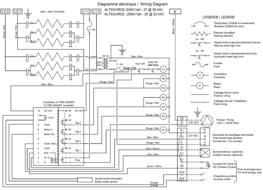
Table of contents
Section 1 : TECHNICAL SPECIFICATIONS ......................................................................................................................................... 3
   1.1POWER AND DIMENSIONS ...................................................................................................................................................... 3
   1.2 BUFFER TANK ......................................................................................................................................................................... 4
   1.3 STORAGE TANK ...................................................................................................................................................................... 4
   1.4 HYDRAULIC SEPARATOR ....................................................................................................................................................... 4
   1.5 BACK UP BOILER..................................................................................................................................................................... 4
      1.5.1 Autonomous electrical mode ............................................................................................................................................. 4
      1.5.2 Automatic transfer mode ................................................................................................................................................... 4
Section 2 : INTRODUCTION ................................................................................................................................................................ 5
   2.1 LOCAL INSTALLATION REGULATIONS .................................................................................................................................. 5
   2.2 CORROSIVE ATMOSPHERE ................................................................................................................................................... 5
   2.3 SHIPMENT INSPECTION ......................................................................................................................................................... 5
   2.4 TO VERIFY ............................................................................................................................................................................... 5
Section 3 : INSTALLATION .................................................................................................................................................................. 6
   3.1 SAFETY MEASURES................................................................................................................................................................ 6
   3.2 LOCATION ................................................................................................................................................................................ 6
   3.3 CLEARANCES .......................................................................................................................................................................... 6
   3.4 PIPING INSTALLATION ............................................................................................................................................................ 7
   3.5 BOILER COMPONENTS ........................................................................................................................................................... 7
   3.6 SYSTEM SETUP ..................................................................................................................................................................... 12
      3.6.1 Connecting the boiler ...................................................................................................................................................... 12
      3.6.2 Flow-check valve ............................................................................................................................................................. 12
      3.6.3 Pressure relief valve ........................................................................................................................................................ 12
      3.6.4 Expansion tank................................................................................................................................................................ 12
      3.6.5 Water pressure regulator ................................................................................................................................................. 12
      3.6.6 Automatic Air Vent........................................................................................................................................................... 12
      3.6.7 Heating pump .................................................................................................................................................................. 13
   3.7 BOILER WIRING: .................................................................................................................................................................... 13
      3.7.1 Main power supply .......................................................................................................................................................... 13
      3.7.2 Heating pump wiring ........................................................................................................................................................ 13
      3.7.3 Outdoor temperature sensor............................................................................................................................................ 13
      3.7.4 Room thermostat wiring................................................................................................................................................... 13
      3.7.5 Automatic transfer mode wiring ...................................................................................................................................... 14
   3.8 WIRING DIAGRAMS ............................................................................................................................................................... 16
Section 4 : ADJUSTMENT OF THE CONTROLLER ........................................................................................................................... 18
   4.1 INTRODUCTION ..................................................................................................................................................................... 18
   4.2 DISPLAYED INFORMATION................................................................................................................................................... 18
   4.3 OPERATION OF THE INTERFACE ........................................................................................................................................ 19
   4.4 OPERATION IN “FIXED BOILER TEMPERATURE SET POINT” ............................................................................................ 19
   4.5 OPERATION WITH “OUTDOOR RESET”: .............................................................................................................................. 19
   4.6 PURGE DELAY OF THE PUMP .............................................................................................................................................. 20
   4.7 AUTOMATIC HEATING SHUT DOWN .................................................................................................................................... 20
   4.8 CONFIGURATION OF THE CONTROLLER............................................................................................................................ 20
   4.9 ADJUSTMENTS OF THE TARGET TEMPERATURE BY THE USER: .................................................................................... 22
   4.10 BOOST SYSTEM OPERATION............................................................................................................................................. 22
   4.11 OPERATION IN AUTOMATIC TRANSFER MODE: ............................................................................................................... 23
Section 5 : START UP OPERATION .................................................................................................................................................. 24
   5.1 PREPARATORY STEP ........................................................................................................................................................... 24
   5.2 STARTUP & INSPECTION ...................................................................................................................................................... 24
   5.3 COMPLEMENTARY CHECKS ON AUTOMATIC TRANSFER MODE ..................................................................................... 24
Section 6 : MAINTENANCE ................................................................................................................................................................ 25
   6.1 INTRODUCTION ..................................................................................................................................................................... 25
   6.1 AT ALL TIMES ........................................................................................................................................................................ 25
   6.2 EVERY 6 MONTHS ................................................................................................................................................................. 25
   6.3 YEARLY INSPECTION............................................................................................................................................................ 25
Section 7 : TROUBLE SHOOTING ..................................................................................................................................................... 26
   7.1 TROUBLE SHOOTING TABLE................................................................................................................................................ 26
   7.2 SPARE PARTS ....................................................................................................................................................................... 28
Section 8 : OPTION DHW HEAT EXCHANGER ................................................................................................................................. 31
AltSource LIMITED WARRANTY ........................................................................................................................................................ 40

        AltSource Electric Boiler Installation, Use and Care Manual (Revision April 2021)                                                                             Page 2.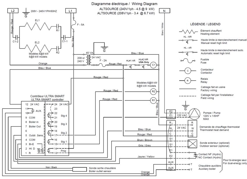
Section 1 : TECHNICAL SPECIFICATIONS
1.1 POWER AND DIMENSIONS

Table 1: Boiler specifications 208V/240V/1ph.1:
                                                                                                    Suggested
                                         Power                                                       electrical        Suggested
          Model
                                          (kW)
                                                             Heating               Amperage2           cable          Breaker/Fuse
        AltSource                                           Elements
                                                                                                     at 240V3           at 240V3
                                 208 V        240V                              208 V    240V       cu        al
              4.5                  3.4           4.5        1 x 4,5 kW            16.3    18.9      10       10            30
                                                           1 x 4.5 kW +
              7.5                  5.6           7.5                              27.2    31.2       8          6          40
                                                             1 x 3 kW
              9                    6.8           9          2 x 4,5 kW            32.6    37.5       8          6          50
              12                    9            12          2 x 6 kW             43.5    50         6          4          70
                                                            2 x 3 kW +
              15                   11.2          15                               54.3    62.5       6          4          80
                                                            2 x 4,5 kW
              18                   13.5          18         4 x 4,5 kW            65.2    75         4          2         100
              20                    15           20          4 x 5 kW             72.5    83.3       3          2         110
              24                    18           24          4 x 6 kW              87     100        2          0         125
              274                  20.3          27         6 x 4,5 kW            97.9   112.5       1       00           150
                                                           2 x 4,5 kW +
              294                  21.8          29                               104     120        1       00           175
                                                             4 x 5 kW
1Electrical supply: 120/240V or 120/208V single-phase (L1 – N – L2) with three 90°C conductors, or two conductors
L1 – L2 if the boiler does not require power to a 120 VAC pump or accessories.
2Add the amperage of the circulating pump and other external accessories if they are connected to the boiler (max.

5A).
3A higher cable size could be required. In all cases the local electrical code has priority. The electrician has the

responsibility to select the appropriate size.
4
  These models are only available on the AltSource 70.

Maximum operating pressure on the tank: 207 kPa / 30 psi
Tank temperature range : 10°C to 88°C (50°F to 190°F)

1 kW = 3412 BTU/h

Table 2: Dimensions:
                                                 AltSource 50                                    AltSource 70
 Height                                            56-7/16’’                                       66-7/16’’
 Diameter                                              22’’                                           24’’
 Depth (with door)                                  25-1/2’’                                          28’’
 Weight                                              280 lb                                          380 lb
 Heating supply                                    1’’ NPTM                                      1-1/4’’ NPTM
 Heating return                                    1’’ NPTM                                      1-1/4’’ NPTM

     AltSource Electric Boiler Installation, Use and Care Manual (Revision April 2021)                      Page 3.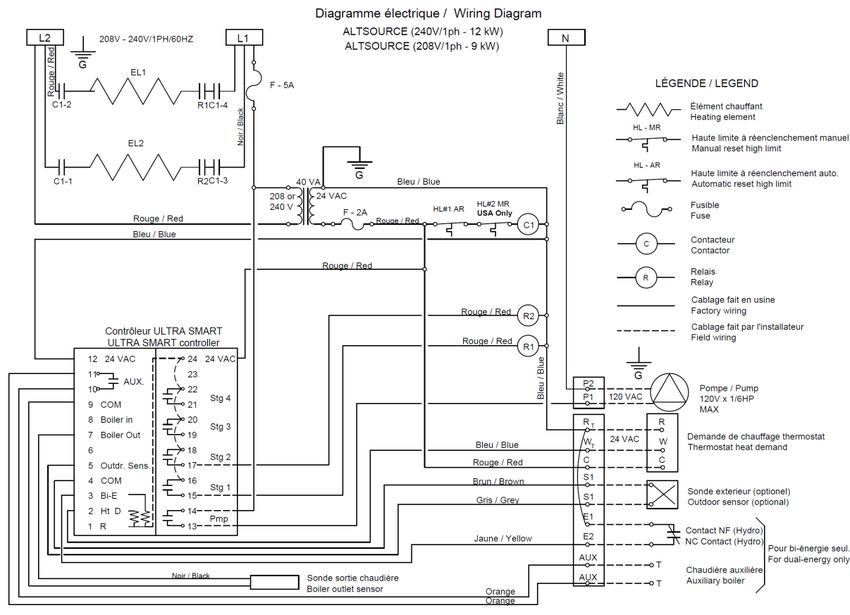
1.2 BUFFER TANK                                                          In addition, for this mode, it is recommended to
The AltSource boiler optimizes runtimes and                              adjust the setpoint of the renewable energy
limits on/off cycling of the energy source(s).                           source to a value greater than 10°F to 20°F than
When the minimum system load is lower than the                           the AltSource to reduce the start-up of the
energy source’s minimum capacity, the system                             electrical elements.
will generate short cycles. This causes premature
wear of the equipment and substantially                                  1.5.2 Automatic transfer mode
decreases the system’s energy efficiency.
                                                                         The boiler can also be operated in the automatic
1.3 STORAGE TANK                                                         transfer mode, where the AltSource electric
Any hydronic heating system with the AltSource                           boiler turns on the distribution pump, reads the
stores energy like a battery. When a demand is                           water temperature and activates the electrical
made for limited heating (for example, when there                        elements if authorized by an external signal. The
is little difference between indoor and outdoor                          elements are then switched on according to the
temperatures) or when it is used with a low-                             adjustment parameters of the UltraSmart
capacity energy source, the energy required will                         controller.
first come from the tank’s thermal storage.

1.4 HYDRAULIC SEPARATOR
Adding an AltSource boiler to a hydronic heating
system helps to evacuate air, eliminates
impurities, and ensures the optimal functioning of
the pumps—not only for the energy source but
also for the distribution system.

1.5 BACK UP BOILER
The addition of an AltSource electric boiler to a
hydronic heating system acts as a back-up
source to the main renewable energy system.
The boiler can operate in two modes:
autonomous electrical mode or automatic
transfer mode.

For both modes, it is recommended to use the
outdoor sensor supplied with the equipment. The
outdoor sensor allows the boiler water
temperature to be modulated according to the
outside temperature. It also makes it possible to
stop the heating of the electric elements when the
outside temperature exceeds a certain
temperature. The use of these functions makes it
possible to optimize the start-up of the main
renewable energy system.

1.5.1 Autonomous electrical mode

By default, the boiler operates in autonomous
electrical mode where, on request of heat, the
AltSource boiler turns on the distribution pump,
reads the water temperature and activates the
electrical elements according to the Parameters
of the UltraSmart controller independently if the
main renewable energy source is on or off.

    AltSource Electric Boiler Installation, Use and Care Manual (Revision April 2021)                      Page 4.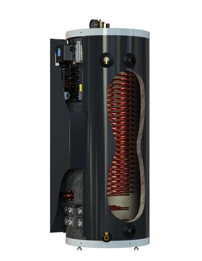
!          General Safety Precautions
Be sure to read and understand the entire Manual before attempting to install or operate
this unit. Pay particular attention to the following General Safety Precautions. Failure to
follow these warnings could cause property damage, bodily injury or death. Should you
have any problems understanding the instructions in this manual, STOP, and get help
from a qualified installer or technician.

                                     Section 2 : INTRODUCTION
    !                  WARNING                                           The following items are factory installed and
The important safeguards and instructions                                shipped with the unit:
appearing in this manual are not meant to                                    • 207 kPa (30 psi) tank pressure relief
cover all possible conditions and situations                                     valve.
that may occur. It should be understood that                                 • Tank drain valve
common sense, caution and care are factors                                   • Thermo manometer (heat and
which cannot be built into every product.                                        pressure indicator).
These factors must be supplied by the                                        • Automatic air vent.
person(s) caring for and operating the unit.                                 • Electric heating elements
                                                                             • ULTRA SMART™ controller.
2.1 LOCAL INSTALLATION
REGULATIONS
This AltSource electric boiler must be installed in                               !            WARNING
accordance with these instructions and must                              The AltSource electric boiler should not be
conform to local regulation, or in the absence of                        located in an area where leakage from the tank
local codes, with the current edition of the                             or water connections will result in damage to
National Plumbing Code and the National Electric                         the adjacent area or to lower floors of the
Code. In any case where instructions in this                             structure. When such areas cannot be
manual differ from local or national codes, the                          avoided, a suitable drain pan or non-
local or national codes take precedence.                                 flammable catch pan, adequately drained,
                                                                         must be installed under the boiler. The pan
2.2 CORROSIVE ATMOSPHERE                                                 must be connected to a drain.
The electric boiler should not be located near an
air supply containing halogenated hydrocarbons
or high humidity. The limited warranty is voided
when failure of the water heater is due to a
corrosive atmosphere.

2.3 SHIPMENT INSPECTION
Inspect the electric boiler for possible shipping
damage. The manufacturer’s responsibility
ceases upon delivery of goods to the carrier in
good condition. Consignee must file any claims
for damage, shortage in shipments, or non-
delivery immediately against carrier.

2.4 TO VERIFY
Please check the boiler identification plate to
ensure you have the right model.

    AltSource Electric Boiler Installation, Use and Care Manual (Revision April 2021)                    Page 5.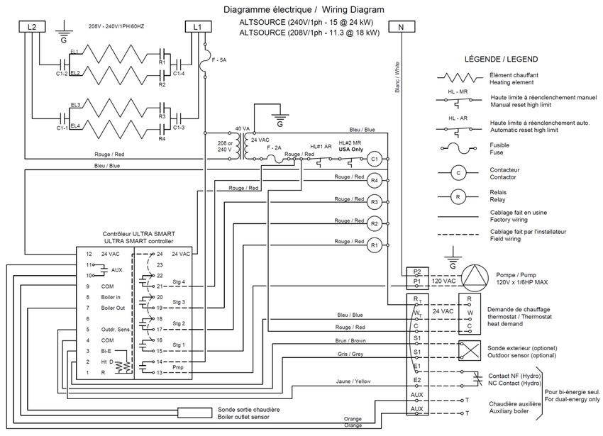
Section 3: INSTALLATION
           !        WARNING                                              All models can be installed on combustible floors
The manufacturer’s warranty does not cover                               and in alcoves.
any damage or defect caused by installation
or attachment or use of any special                                      3.3 CLEARANCES
attachment other than those authorized by the                            The minimal clearances required for proper
manufacturer into, onto, or in conjunction                               inspection and servicing are as follows.
with the water heater. The use of such                                   Supplementary clearances could be required for
unauthorized devices may shorten the life of                             piping installation.
the water heater and may endanger life and
property. The manufacturer disclaims any                                 Table 3: Minimum clearances required
responsibility for such loss or injury resulting                                        Left side          0 mm/ 0 ‘’
from the use of such unauthorized devices.                                            Right side           0 mm/ 0 ‘’
                                                                                           Top           127 mm / 5 ’’
3.1 SAFETY MEASURES                                                                      Front*           75 mm / 3 ’’
All installations will include a pressure relief valve                                    Back             0 mm/ 0 ‘’
limiting the operating pressure to 207 kPa (30                           *If the installation is inside a closet with an access
psi).                                                                    door, ventilation openings could be required to
                                                                         maintain the ambient temperature below 32°C
This AltSource electric boiler is designed for a                         (90°F).
maximum operating temperature of 88°C
(190°F). It is designed for hot water heating
systems only. When allowed by local regulation a
maximum 50% blend of water and antifreeze (
designed specifically for water heating systems)
may be used.

The boiler is equipped with an automatic high limit
temperature control set at 210°F (99°C) and
models sale in USA have a second limit device
manually re-settable set at 227°F (108°C). If the
heating distribution system on which the boiler is
installed requires a high limit controller having a
lower setting, this controller will be added to the
system and connected in series with the factory
installed limit control.

3.2 LOCATION
The AltSource boiler should be installed in a
clean, dry location. Long hot water lines should
be insulated to conserve energy. The boiler and
piping should be protected from exposure to
freezing.

The AltSource boiler must be installed levelled
and vertically. Adjustable legs allow for levelling
and stability.

The AltSource boiler must be located or protected
so as not to be subject to physical damage, for
example, by moving vehicles, area flooding, etc.

    AltSource Electric Boiler Installation, Use and Care Manual (Revision April 2021)                         Page 6.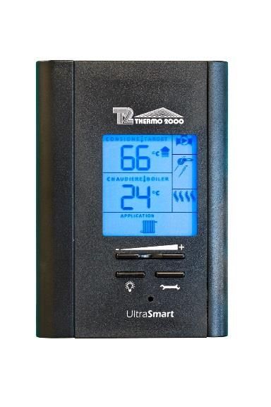
3.4 PIPING INSTALLATION
Make sure that the installation complies with one
of the configuration shown below and that the
water circulation is done in the right way.
Figure 1: Possible installation configurations
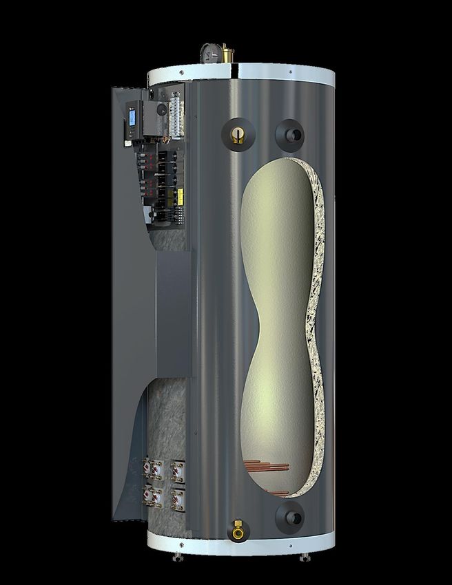
3.5 BOILER COMPONENTS
Figures 2 and 3 show various components of the autonomous electrical mode. Figures 5, 7 and 8
AltSource electric boiler. Figures 4 and 6 show show some installation drawings of the boiler in
some installation drawings of the boiler in the the automatic transfer mode.
Automatic air vent
Main Electrical Supply Temperature and pressure
indicator
Low voltage
connections
Pressure relief valve (30 psi)
Heating supply
Model 50: 1” NPTM
Model 70: 1 ¼“ NPTM
Figure 2 : Components identification and location (top right side view)
AltSource Electric Boiler Installation, Use and Care Manual (Revision April 2021) Page 7.
UltraSmart controller
                                                                                     Heating supply
                                                                                     Model 50: 1” NPTM
                                                                                     Model 70: 1 ¼“ NPTM
Electrical components
mounting panel

    Heating elements

                                                                                    Heating return
                                                                                    Model 50: 1” NPTM
                                                                                    Model 70: 1 ¼“ NPTM

                                                                                    Adjustable feet
                                                          Drain valve

                   Figure 3: Components identification and location (left side view)

AltSource Electric Boiler Installation, Use and Care Manual (Revision April 2021)              Page 8.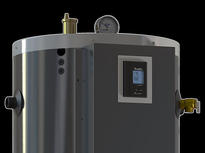
AltSource INSTALLED WITH WOOD BOILER
                                      AUTONOMOUS ELECTRICAL MODE
               Legend

                        Outdoor sensor                      Automatic air vent
                                                                                     Expansion tank
                        Circulating pump
                                                            Air seperaor
                        Room thermostat
                                                                                     Pressure regulator
                        Pressure and temperature            Pressure relief valve
                        indicator
                                                                                     Thermostatic mixing valve
                        Drain valve                         Union
                                                                                     Service valve
                                                                                     Back flow preventor

   120 V

        Wood boiler                                           AltSource

                     Figure 4: Basic dual energy Installation drawing for radiant floor.
                                 AltSource INSTALLED WITH WOOD BOILER
                   Legend              AUTOMATIC TRANSFER MODE
                        Outdoor sensor
                                                         Automatic air vent
                       Circulating pump                                             Expansion tank
                                                         Air seperaor
                       Room thermostat
                       Pressure and temperature                                     Pressure regulator
                                                         Pressure relief valve
                       indicator                                                    Thermostatic mixing
                       Drain valve                       Union                      valve

                                                                                    Service valve
                                                                                    Back flow preventor
               TT

              RA89                                     EE

120 V    21   34

  Chaudière au bois                                          AltSource

              Figure 5: Dual energy Installation drawing for radiant floor and wood boiler.

AltSource Electric Boiler Installation, Use and Care Manual (Revision April 2021)                     Page 9.
AltSource INSTALLED WITH AIR-TO-WATER HEAT PUMP
             Legend         AUTONOMOUS ELECTRICALMODE
                   Outdoor sensor                        Automatic air vent

                   Circulating pump                                                 Expansion tank
                                                         Air seperaor
                   Room thermostat
                   Pressure and temperature                                         Pressure regulator
                   indicator                             Pressure relief valve
                                                                                    Thermostatic mixing
                   Drain valve                           Union                      valve
                                                                                    Service valve
                                                                                    Back flow preventor

      Air-to-water heat pump                                     AltSource

Figure 6: Basic dual energy Installation drawing for radiant floor and Air-to-water heat pump

                   AltSource INSTALLED WITH AIR-TO-WATER HEAT PUMP
             Legend            AUTOMATIC TRANSFER MODE
                   Outdoor sensor                        Automatic air vent
                   Circulating pump                                                 Expansion tank
                                                         Air seperaor
                   Room thermostat
                   Pressure and temperature                                         Pressure regulator
                   indicator                             Pressure relief valve
                                                                                    Thermostatic mixing
                   Drain valve                           Union                      valve

                                                                                    Service valve

                                                                                    Back flow preventor

                                                           EE

    Air-to-water heat pump
                                                                 AltSource

   Figure 7: Dual energy Installation drawing for radiant floor and Air-to-water heat pump

AltSource Electric Boiler Installation, Use and Care Manual (Revision April 2021)                    Page 10.
AltSource INSTALLED WITH AIR-TO-WATER HEAT PUMP
Legend AUTOMATIC TRANSFER MODE
Outdoor sensor
Éliminateur d’air automatique
Circulating pump Expansion tank
Room thermostat Air seperaor
Pressure and temperature Pressure regulator
indicator Pressure relief valve
Thermostatic mixing
Drain valve Union valve
Service valve
Back flow preventor
EE
Diverter valve
AltSource
Air-to-water heat pump
Cooling system
Figure 8: Dual energy Installation drawing for radiant floor and Air-to-water heat pump
AltSource Electric Boiler Installation, Use and Care Manual (Revision April 2021) Page 11.3.6 SYSTEM SETUP The expansion tank is used to absorb the
Figures 2 to 8 indentify and show location of the increase of water volume from the boiler and the
different components. They also provide typical system when it is working.
heating system installation. External components The model selection should be based on the
location may vary in order to accommodate maximum working temperature and the water
specific installation and local codes and volume of the total system. For example, a
regulation. system with radiators contains much more water
volume than a baseboards system. Likewise, the
3.6.1 Connecting the boiler AltSource also contains an important volume of
The boiler heating supply and return connections water that has to be added :
are located on the left or right side and are 1”
NPTM for Model 50 and 1-¼’’ NPTM for model AltSource 50 : 48 usgal
70. The connections at the left or right can be AltSource 70 : 71 usgal
used.
Unions are recommended on the inlet and outlet With this information, the installator or distributor
pipes to disconnect the water heater easily for should be able to make an appropriate selection
servicing if necessary. for an expansion tank.
Dielectric (insulating) unions should be used if
copper-steel connections are made. Here are some minimal recommendations for
Insulate all pipes containing hot water, especially different types of heating systems.
in unheated areas.
Radiant Cast-iron
AltSource Baseboards
3.6.2 Flow-check valve floor radiators
If the heating system uses a single or multiple
circulators without motorized zone valves, a flow- AltSource 50 #30 #30 #60
check valve must be installed to avoid all
possibility of gravity flow and heat loss during
non-draw periods. Modern circulators are AltSource 70 #60 #60 #90
typically provided with spring loaded check valves
that will provide adequate protection.
If the heating system uses motorized zone The expansion tank is generally installed on the
valves, these will provide adequate protection. wall or ceiling. It also has to be well supported.
3.6.3 Pressure relief valve 3.6.5 Water pressure regulator
The boiler is delivered with a factory installed tank The boiler should be installed in such a way that
pressure relief valve set at 207 kPa (30 psi). it can automatically be fed with water in the event
NEVER replace the pressure relief valve by a of a pressure drop.
higher set pressure one. The minimum pressure obtained when the
Connect the outlet of the relief valve downward system is cold is generally 12 psi (83 kPa).
toward a safe location. This accessory shall be equipped with one or
Relief valve outlet pipe diameter must not be of more check valves to avoid all possibilities of the
smaller diameter than the relief valve outlet. The boiler water returning to the potable water supply
oulet pipe end must be visible in order to observe network (local regulation should be applied)
any relief incident and be protected from freezing.
NEVER cap or plug a pressure relief valve 3.6.6 Automatic Air Vent
outlet. The pressure relief valve is a safety The AltSource has a factory installed tank
apparatus and preventing its proper operation automatic air vent. This air vent function is to vent
may cause death, injury or property damage. any air present in the tank.
For proper operation, do not cap or block the air
3.6.4 Expansion tank bleeder outlet.
When operating the AltSource and the heating For proper operation of the heating system, it may
system, pressure will vary between 83 kPa and be necessary to add air bleeders to the heating
193 kPa (12 psi to 28 psi). The operating system circuits.
pressure is affected by the type of heating system
and the size of the expansion tank installed.
AltSource Electric Boiler Installation, Use and Care Manual (Revision April 2021) Page 12.3.6.7 Heating pump 3.7.3 Outdoor temperature sensor
A circulating pump (not included) is required for If you want the boiler target temperature to
the heating system to deliver heating fluid to the modulate according to the outdoor temperature
different heating zones. Sizing of the pump is (when the outdoor temp. will get colder, the target
base on the heating system configuration and is temperature will get higher). The supplied
done by the installator (heating technician, outdoor sensor will have to be connected to S1
plumber). S1 before turning the power on to the unit.
The installation of this sensor cancels the
3.7 BOILER WIRING: operation of the boiler when the outdoor
temperature exceeds the selected value
3.7.1 Main power supply corresponding to the maximum temperature
The electrical wiring and grounding must conform required for heating.
to local codes or, in their absence, to the National
Electrical Code. Local codes have authority for This control strategy optimize the use of the main
wiring and electric breaker sizing. It is the renewable energy source by reducing the use of
electrical technician responsibility to insure that electric elements of the AltSource boiler.
the installation meets the applicable codes
requirements. 1. Sensor location:
-Outside the building at a location which best
On installation where a 120 Vac power is required represents the heat demand of the building (a
for a heating pump and other outboard wall facing north for most of the buildings and on
components, main power supply to the AltSource a south one on buildings with large windows
must be a 120/240 Vac, single phase, 60 Hz facing south).
using 3 conductors (L1 – L2 – N) and a ground -It should not be exposed to external heat
wire. sources (dryer outlet, window openings,
uninsulated walls).
On installation where no 120 volts external -It should not be installed in a location where it
components need to be powered by the could be covered with snow.
AltSource, Power supply could then be supplied
with only two conductors L1-L2 with a ground 2. Installation:
wire. -Drill a 9/64” dia. hole through the wall and insert
the sensor cable.
Electrical current draw for the boiler being -Fix the sensor cover to the wall using supplied
installed is indicated on the boiler’s name plate. screw.
The electrical technician needs this information in -With an electric cable (100ft max.) having 2
order to determine the proper electrical breaker conductors 20ga. connect one end of this cable
and cable. The cable can be either aluminum or to the sensor cable using twist-on wire
copper, but must be adequate for 75°C operation. connectors and the other end to terminals S1 &
S1 of the boiler.
If aluminum cables are used, it shall be of an
adequate size (generally bigger) and particular If you wish to operate the boiler at a fixed target
consideration will have to be respected such as temperature, simply do not connect the sensor
the use of DE-OX inhibitors in order to meet the before applying the power to the unit (do not put
National electrical code. a jumper between S1&S1 if the outdoor sensor is
not used).
3.7.2 Heating pump wiring
3.7.4 Room thermostat wiring
If the building heating system is designed for a
single pump operation and the electrical power to
the boiler is 120/240 Vac 3 conductors and 3.7.4.1 Single heating zone
ground type, the pump (1/6 HP max) can be Using a two (2) wires central thermostat, connect
directly connected to the boiler electric panel “PP” the low-voltage thermostat dry contact to the W
terminals. The boiler control will operate the and R terminals on the AltSource electrical panel.
pump as soon as a heat demand is signalled by Using a three (3) wires central thermostat,
the space thermostat. connect the C, W and R terminals to the boiler
electric panel corresponding terminals.
AltSource Electric Boiler Installation, Use and Care Manual (Revision April 2021) Page 13.DO NOT apply external current to these two positions “ELECT” and “Bi-Energ”.
terminals. Position the switch at “Bi-Energ” (see fig.9)
• Install a 2 wire 18ga cable between the
3.7.4.2 Zone valve zoning contact (NC contact to allow the operation in
Connect the low-voltage thermostat to the zone electricity) of the external device making the
valve motor. The components must wired such selection of the operating mode and
that, upon a heating demand from a thermostat, terminals E1 E2 (see fig.10)
only the corresponding zone valve will be • Install a pump relay (such as Honeywell
actuated and will in turn activate the AltSource. RA832 or TACO SR501-4) near the
Connect the zone valve dry end switch contact to renewable energy source to authorize the
the W and R boiler electrical panel terminals AltSource control the start up your
renewable energy source. (see fig.10)
- The relay can be supplied by an external
120V source or directly from the boiler fuse
and P2 neutral.
- Install a 2 wire 18-gauge cable between the
“AUX” of the AltSource and “TT” of the
relay RA832 (or R and W of relay TACO
501-4)
- Connect the auxiliary pump wires on the
relay terminals.
AltSource - Connect the electric terminal of the
renewable energy on the “XX” relay RA832
terminals or 6-5 of the relay TACO 501-4
(see fig.10)
The 24 Vac power supply transformer used - The renewable energy source must be be
must be powerful enough to supply controlled by its own operation and limiting
simultaneously all zone valves. controller.
3.7.5 Automatic transfer mode wiring Do not connect the main electrical supply
If needed, The AltSource boiler is designed to of the renewable energy source to AUX
automatically transfer the right energy source to terminals.
be in function. The automatic transfer mode is not
set by default. This mode allows to activate the
electric elements upon reception of an external
signal. The AltSource will select the appropriate
energy source and will activate the renewable
energy source or the electic boiler. If the heating
distribution system is equipped with a single
pump connected to the PP terminals of the boiler,
it will be activated on heat calls from the
thermostat, whichever the energy source
selected.
To allow the operation in automatic transfer
mode:
• Open the front access panel to the boiler
electric compartment. Remove the screw at
the bottom of the controller; raise the upper
section of the controller. You will see a Figure 9: Back of the Controller
switch at the back of the controller having
AltSource Electric Boiler Installation, Use and Care Manual (Revision April 2021) Page 14.External signal
Figure 10: Wiring diagram with auxiliary energy source
It is also possible to allow the renewable energy the request, (closed contact between E1 & E2)
source to be operated according to its own the heating elements will be activated according
controls at all times (do not use the AltSource to the operating parameters of the controller.
contact of the "AUX" terminals) and when the
main renewable energy source is not sufficient to
AltSource Electric Boiler Installation, Use and Care Manual (Revision April 2021) Page 15.3.8 WIRING DIAGRAMS AltSource Electric Boiler Installation, Use and Care Manual (Revision April 2021) Page 16.
AltSource Electric Boiler Installation, Use and Care Manual (Revision April 2021) Page 17.
Section 4 : ADJUSTMENT OF THE CONTROLLER
4.1 INTRODUCTION                                                         4.2 DISPLAYED INFORMATION
The AltSource boiler is mainly designed to be                            The electronic control uses an LCD display to
installed on closed circuit applications where the                       make all adjustments and to visualize the
water of the heating system flows directly from                          operation of the system.
the boiler to the heating distribution system
(Standard parallel Piping system)
Two operation modes are then offered:
❑ Fixed boiler temperature set point (the
  outdoor sensor shall not be installed)
Or
❑ Outdoor reset

                                       Figure 11 : UltraSmart Controller Display

    AltSource Electric Boiler Installation, Use and Care Manual (Revision April 2021)                  Page 18.
4.3 OPERATION OF THE INTERFACE
The controller uses four push buttons at the
bottom of the display to select and adjust the
parameters.
The button is used to access the
configuration menu and confirm a selection.
The buttons are used to select
an item or adjust a value.
The button enables the illumination of the
display under two different modes.
The default mode will enable the illumination of
the display for a period of 10 sec. each time a
button is pressed. If the is pushed, the light will
be continuously illuminated. Just press the button
to change the mode of activation.
Figure 12 : UltraSmart Control Module
4.4 OPERATION IN “FIXED BOILER N.B. The supplied outdoor temperature sensor
TEMPERATURE SET POINT” must be connected before applying the electrical
For installation where the boiler target power to the unit.
temperature shall be maintained at a fixed The boiler target temperature will be calculated
temperature that will not vary in relation to the by the controller in relation to the parameters
outdoor temperature, the sequence of operation selected in the menu
will be as follow:
On a call for heat from the room thermostat, the
and the
circulating pump will start and the boiler will
maximum target temperature required when the
activate the number of stages required to get to
outdoor temperature will get to -10°F (-23°C). The
and maintain the outlet temperature of the boiler
“STD” curve corresponds to the default maximum
near the selected target temperature. A rotation
of the stages based on an equal time period of temperature for a typical system and this value
can be modified from the “MIN” to “MAX” value
operation is provided.
shown on the following tables.
N.B. The supplied outdoor temperature sensor
shall not be connected before applying the
electrical power to the unit
4.5 OPERATION WITH “OUTDOOR
RESET”:
For installation where the boiler target
temperature shall modulate in relation to the
outdoor temperature; when the outdoor
temperature gets colder, the boiler target
temperature will increase.
On a call from the room thermostat, the
circulating pump will start and the boiler will
activate the number of stages required to get to
and maintain the outlet boiler temperature near
the target temperature established by the
controller according to the outdoor temperature.
A rotation of the stages based on an equal time
period of operation is provided.
AltSource Electric Boiler Installation, Use and Care Manual (Revision April 2021) Page 19.The following tables show the values of the target 4.6 PURGE DELAY OF THE PUMP
temperature that will be obtained in relation to the The controller offers the possibility to
outdoor temperature. stop the operation of the pump after an adjustable delay
PLINTHES CHAUFFANTES À AILLETTES
190F/88C
FINNED-TUBE HOT WATER BASEBOARDS once the heat demand has been completed.
MAX
The following choices are offered:
Temp. de consigne / Target temp.
180F/82C
❑ “OFF” The pump will stop immediately when the
STD
170F/77C
160F/71C
MIN heat demand has been satisfied. This selection
shall be selected on systems equipped with
150F/65C
motorised fast closing zone valves in order to
140F/60C
prevent noise from water hammering.
❑ “15 sec to 60 min” delay where the pump will be
130F/54C
120F/49C
kept running to enable the pump to circulate
110F/43C
80F
27C
70F
21C
60F
15C
50F
10C
40F
4C
30F
0C
20F
-7C
10F
-12C
0F
-17C
-10F
-23C
-20F
-29C
water into the system to equilibrate the heat in all
Température ext. / Outdoor temperature the building.
PLANCHER CHAUFFANT DANS BÉTON ❑ “ON” The pump is in continuous operation.
RADIANT FLOOR IN CONCRETE
130F/54C
Required on particular heating distribution
Temp. de consigne / Target temp.
120F/49C MAX systems.
110F/43C
STD
100F/-38C
4.7 AUTOMATIC HEATING
90F/32C
MIN SHUT DOWN
80F/27C
When the outdoor sensor is installed and the unit then
70F/21C
80F 70F 60F 50F 40F 30F 20F 10F 0F -10F -20F operates in the “outdoor reset” mode, the controller offers
27C 21C 15C 10C 4C 0C -7C -12C -17C -23C -29C
Température ext. / Outdoor temperature the user the possibility to automatically stop the boiler
when the outdoor temperature reaches an adjustable
PLANCHER CHAUFFANT ENTRE SOLIVES value (0°F (-17°C) à 105°F (40°C). This characteristic is
RADIANT FLOOR BETWEEN JOISTS MAX
140F/60C especially interesting on the following applications:
130F/54C -Heating systems equipped with many thermostats
Temp. de consigne / Target temp.
STD
120F/49C where the user wants to prevent the operation of the unit
110F/43C
MIN
if one of the thermostats has inadvertently been
100F/-38C activated.
90F/32C -Heating systems where the owner supplies heat to a
80F/27C
80F 70F 60F 50F 40F 30F 20F 10F 0F -10F -20F
lodger
27C 21C 15C 10C 4C 0C -7C -12C -17C -23C -29C -Systems connected to a geothermic or air-water
Température ext. / Outdoor temperature
heat pump where we do not want the electric boiler
RADIATEURS EN FONTE to be operating unless the outdoor temperature
CAST IRON RADIATORS
170F/77C
MAX drops to a selected degree.
160F/71C
STD
150F/65C 4.8 CONFIGURATION OF THE CONTROLLER
Temp. de consigne / Target temp.
140F/60C
MIN Since each type of heating distribution system is
130F/54C designed to operate at water temperatures that are
120F/49C particular to its operation, the proper configuration of the
110F/43C operating parameters of this particular system is
100F/-38C important to maximize its performance.
90F/32C
80F 70F 60F 50F 40F 30F 20F 10F 0F -10F -20F
In order to do this, the installer will first have to tell the
27C 21C 15C 10C 4C 0C -7C -12C -17C -23C -29C controller if the application is in automatic transfer mode
Température ext. / Outdoor temperature
or autonomous electric mode. The selection is made by
selecting the position “Elect.” for the autonomous electric
mode Or “Bi-Energ” for the automatic transfer mode on
the switch located at the back of the controller. This
selection will have to be made before applying voltage to
the unit. The default setting is the autonomous electric
mode “Elect.”
AltSource Electric Boiler Installation, Use and Care Manual (Revision Sept .2019) Page 20.This being done, the installer will have to access the
configuration menu by pressing the button for 2
sec. until the first menu appears. The selection of the
item or value is made by pressing the
button and by pressing the button to get to the
next menu. See table 1 below to visualize the menu list
that will gradually be displayed.
If the buttons remain untouched for a period of 10 sec.,
the controller will register the value of the selection made
and return to the regular display position. It will also
return to the regular display after reviewing all the
operating parameters of the controller.
In case of a power failure, the parameters will be restored
as they were established before the failure.
Figure 13 : Back of the controller
Table 5 below shows the presentation sequence of the
menus.
Table 6: CONFIGURATION SEQUENCE OF THE MENU (Press on the button for 2 seconds)
ITEM DESCRIPTION RANGE DEFAULT
Choose the units the user prefers to work with °F or °C °F
-Radiant Floor in
concrete
-Radiant Floor between
joists
Select the type of heating system on which the
-Cast iron radiator
boiler will be installed.
-Hot water baseboards
Adjust the maximum boiler target temperature -Radiant Floor in 100°F
required to adequately heat the building when the concrete
outdoor temperature is very cold. 85°F to 115°F
It is recommended to adjust the setpoint of the -Radiant Floor between 125°F
renewable energy source to a value greater than joists 110°F to 140°F
10 ° F to 20 ° F to the one of the AltSource to
reduce the start-up of the electrical elements, more -Cast iron radiator 135°F 150°F
particularly when the autonomous electric mode is to 165°F
used.
-Baseboard
160°F to 185°F 175°F
AltSource Electric Boiler Installation, Use and Care Manual (Revision Sept.2019) Page 21.Select the purge period that the pump will be
OFF
running once the heat demand is completed.
15 sec. to 60min. 30sec
Select OFF if the heat system is equipped with
ON
electric zone valves.
Select the outdoor temperature at which no
heating of the building is required or the outdoor
temperature at which you allow the electrical
0°F à 105°F 75°F
elements to be in function as a backup to your
main system. (the outdoor sensor has to be
installed)
Note 1: Once the operating parameters have been set, the controller will automatically come back to normal
display screen. If the user needs to increase or decrease the target temperature, he can do it without having
to enter in the configuration menu (see the following section).
4.9 ADJUSTMENTS OF THE TARGET -Long periods without heating which needs higher boiler
TEMPERATURE BY THE USER: temperature to recuperate.
HAUSSE AUTOMATIQUE DU POINT DE CONSIGNE
« BOOST » -Return to normal room temperature after thermostat’s
By pressing the button, the end
AUTOMATIC INCREASE OF TARGET TEMPERATURE “night set back” program.
user has the possibility to offset the programmed target
Temp. de consigne / Target temp.
130F/54C
temperature without going through the tool menus.
120F/49C
Three “Boost” operating options are available when the
When
110F/43C
the + or - button is pressed, the value “0” will
appear and blink to show a “0” offset value from the is pressed for 6 sec. The icon will appear and
ST
BOO m
100F/-38C
original settings. When the + mor axim - buttons are pressed
u the three options ON1, ON2 and OFF will be proposed.
again the offset value will change up
90F/32C to a value of ± 10°F
NOR
M AL Press the button to select. The
(5°C) from the original setting made
80F/27C in the configuration
controller will register the selected item and will return to
menu. The new value will blink during 5 sec. and the
70F/21C
80F 70F 60F 50F 40F 30F 20F 10F 0F -10F -20F normal operation after 5 sec.
display will27C then
21C go back
15C 10C to
4C the 0C standard
-7C -12C view and -29C
-17C -23C the
new target temperature will beext.shown.
Température / Outdoor temperature
Operation in “Boost” Option ON1 (default setting)
Afterward, when the button will be The controller will engage the “Boost” program when the
pressed, it will show the value of the offset made heat demand on terminals RW has been maintained for
previously and can be re-adjusted. a pre-determined period according to the type of selected
application. Once this period has been reached, the
OPERATION OF THE +DES
FONCTIONNEMENT - BUTTONS
TOUCHES “Boost” icon will appear on the display and the boiler
target temperature will start increasing very slowly over
Temp. de consigne / Target temp.
130F/54C
a pre-determined period and up to a pre-calculated
120F/49C
tm ax. maximum value until the heat demand applied on RW
Offse
110F/43C terminals has been completed.
100F/-38C NOR
M AL On a new heat demand, the previous boost period is
90F/32C
forgotten and the boiler target gets back to its original
tm in.
Offse setting
80F/27C
70F/21C
80F 70F 60F 50F 40F 30F 20F 10F 0F -10F -20F Operation in “Boost” Option ON2 (only offered on
27C 21C 15C 10C 4C 0C -7C -12C -17C -23C -29C installation not operating in Dual-energy)
Température ext. / Outdoor temperature
4.10 BOOST SYSTEM OPERATION The boost program is a marvellous feature that works
The controller incorporates a unique feature that enables fine on applications where the number of room
the target boiler temperature to automatically be thermostats is in limited quantity otherwise it may happen
increased when the building heat load increases but that during very cold periods the heat demand from all
cannot be fulfilled with the actual boiler target the thermostats may not become satisfied.
temperature and consequently the room thermostat(s) This option requires the installation of one or two stages
cannot be satisfied within a pre-determined period. heating thermostats. The second stage of the
Example: thermostat(s) will have to be connected to E1-E2 of the
-Return to normal heat load after low demand periods boiler and the option ON2 selected.
occurring during sunny days. Then the Boost mode will be instantaneously started
increasing the target temperature when the signal from
AltSource Electric Boiler Installation, Use and Care Manual (Revision Sept.2019) Page 22.the second heating stage will be received. The target Upon reception of a heat demand on terminals R W of
temperature will immediately
HAUSSE AUTOMATIQUE DUstart
POINT DEincreasing.
CONSIGNE the AltSource boiler, terminals P1&P2 will be energized at
« BOOST » 120volts and the pump will be activated. At the same
AUTOMATIC INCREASE OF TARGET TEMPERATURE
time, the contact will close on the “AUX” terminals to
Temp. de consigne / Target temp.
130F/54C
120F/49C
activate the auxiliary boiler. This boiler will be activated
only when there will be a heat demand to the R W
110F/43C
terminals and when the auxiliary boiler temperature will
100F/-38C
BOO
ST be lower than the settings of its own temperature
90F/32C controls.
MA L
NOR
80F/27C
Using the "AUX" terminals on the AltSource to allow the
70F/21C
80F 70F 60F 50F 40F 30F 20F 10F 0F -10F -20F start-up of the renewable energy source, you operate
27C 21C 15C 10C 4C 0C -7C -12C -17C -23C -29C either with the renewable energy source or with
Température ext. / Outdoor temperature
electricity.
N.B. If the system is in “boost” most of the time, this It is also possible to allow the renewable energy source
means that the boiler target parameter established to be operated according to its own controls at all times
during “Setting procedure” would be too low for the (do not use the contact of the "AUX" terminals) and when
heating system on which the unit is applied. This boiler the latter is not sufficient to the request, (closed contact
target could simply be gradually increased by pressing between E1 & E2) the heating elements will be activated
the + button or by re-setting the operating parameters according to the operating parameters established
using the tool menus . previously.
The Boost menu can be cancelled by selecting “OFF” in
the Boost menu. Manual selection for the electricity or renewable
energy source.
4.11 OPERATION IN AUTOMATIC TRANSFER If the user wishes to manually select the electricity or
MODE: renewable energy source, it can be done in following the
In automatic transfer mode, the display will indicate that sequence below:
this mode is active in showing the icon o Push on the button for 6 sec. and the
following icons will appear
If it is not shown, check the position of the switch located
at the back of the controller. It must be set to “Bi-Energ” The selection of the dual-energy or electric only or
position. auxiliary boiler only is made with the + - button. Once the
N.B. The controller will have to be reset to register the selection has been made it will be registered by pressing
new mode of operation. Just turn the power OFF and the or by waiting for 5sec.
back ON to the unit.
If the electricity only or auxiliary boiler only has been
Operation in automatic transfer mode with Electric
Boiler selected, the corresponding icon and the icons will
When the authorisation signal to operate in electricity is blink to advise the user that an unusual heating mode
received, (closed contact between E1 & E2), the following has been selected.
icons will be shown.
The circulating pump and the heating elements will be
activated according to the operating parameters
established earlier.
Operation in automatic transfer mode with
Renewable energy source
When the authorisation signal will be absent (open
contact between E1&E2), the following icons will be
shown.
AltSource Electric Boiler Installation, Use and Care Manual (Revision Sept.2019) Page 23.Section 5 : START UP OPERATION
! SAFETY PRECAUTIONS
!
Before operating this boiler, be sure to read and follow these instructions, as well as the warnings
printed in this manual. Failure to do so can result in unsafe operation of the boiler resulting in
property damage, bodily injury, or death. Should you have any problems reading, following or
difficulty in understanding the instructions in this manual, STOP, and get help from a qualified
person.
Do not turn on the boiler unless it is filled with water. Do not turn on the boiler if the cold water
supply shut-off valve is closed.
5.1 PREPARATORY STEP simultaneously the + and – buttons and
❑ Make sure that all the piping and electrical maintaining the pressure on the buttons until all
connections have been made. the components are operating
❑ Fill the boiler and the heating system with water. ❑ Measure the amperage value drawn by the unit.
❑ Check for leaks. It shall be around the value indicated on the
❑ Check the pressure reading at the temperature boiler name plate.
and pressure indicator. It should be around 12 ❑ Partially close the isolating valve at the outlet of
psi. the boiler to reduce the water flow and
❑ Turn On the electrical supply to the boiler with no consequently slowly increase the outlet
heat demand from the thermostat(s). temperature. The heating elements shall
❑ If the boiler is installed in automatic transfer gradually stop as the temperature increases and
mode, adjust the external device making the gets near the target temperature.
selection of the heating mode for an operation on ❑ Lower the adjustment of the room thermostat(s).
Electricity (close contact between E1&E2). The heating elements shall stop and the pump
❑ Completely eliminate all the air from the boiler shall stop after the delay set on the controller.
and the distribution piping system. To do so, ❑ Check the pressure reading on the gauge of the
activate the circulating pump without the heating unit. It should not be higher than 28 psi when the
elements. If the pump is connected directly on distribution system will get to its maximum
PP terminals of the boiler, it can be activated by operating temperature.
selecting “ON” in the configuration menu
after having pressed for 2 seconds.
5.3 COMPLEMENTARY CHECKS ON
❑ Do not set the room thermostat at ON to avoid AUTOMATIC TRANSFER MODE
the operation of the heating elements. ❑ Check the proper operation of the external
❑ Adjust the UltraSmart boiler temperature authorization signal to operate on electricity or
controller as explained earlier and set the purge auxiliary in simulating the operation of the signal
delay of the pump from On to its normal (open or close contact) on E1 and E2. Verify the
operation setting. The pump should stop. change of the operating mode.
❑ Check the operating sequence in the “AUX”
mode as decrribed in section 4.11 of the manual.
5.2 STARTUP & INSPECTION
❑ Adjust and check the operation of the auxiliary
❑ Set the room thermostat ON to generate a heat
boiler.
demand.
❑ The pump shall start. The heating elements shall
N.B. On initial startup it may take a considerable amount
gradually come on and the boiler temperature
of time before the water reaches the target temperature
will increase.
Further adjustments may be necessary as you use your
N.B: A rapid activation of all the elements and
boiler and the space heating system.
external components can be done by pressing
AltSource Electric Boiler Installation, Use and Care Manual (Revision Sept .2019) Page 24.You can also read