Graduate Team Aircraft Design Competition: Electric Vertical Takeoff and Landing (E-VTOL) Aircraft Mistral Air Taxi - AIAA
←
→
Page content transcription
If your browser does not render page correctly, please read the page content below
Graduate Team Aircraft Design Competition:
Electric Vertical Takeoff and Landing (E-VTOL) Aircraft
 Mistral Air Taxi

 Team Name: The Huggy’s Birds

 S. ADDARKAOUI TAARABT A. BERNIER

 Y. CHEN H. COMPERE

 A. DORE M. FRANSOLET

 R. JUMPERTZ L. MACCHIAIOLO

 Faculty members:

 Prof. G. DIMITRIADIS Prof. L. NOELS

 A. CROVATO T. LAMBERT

 AIAA G RADUATE T EAM A IRCRAFT D ESIGN C OMPETITION 2018-2019
Team member AIAA number Email adress Signature

Saddik ADDARKAOUI 976674 s.addarkaoui@student.uliege.be

 Albin BERNIER 976496 Albin.bernier@student.uliege.be

 Yusi CHEN 977157 Yusi.Chen@student.uliege.be

 Haiming COMPERE 976490 Haiming.Compere@student.uliege.be

 Antoine DORE 976493 antoine.dore@student.uliege.be

Maxime FRANSOLET 977254 Maxime.Fransolet@student.uliege.be

 Remy JUMPERTZ 965295 Remy.Jumpertz@student.uliege.be

Luca MACCHIAIOLO 976966 luca.macchiaiolo@student.uliege.be
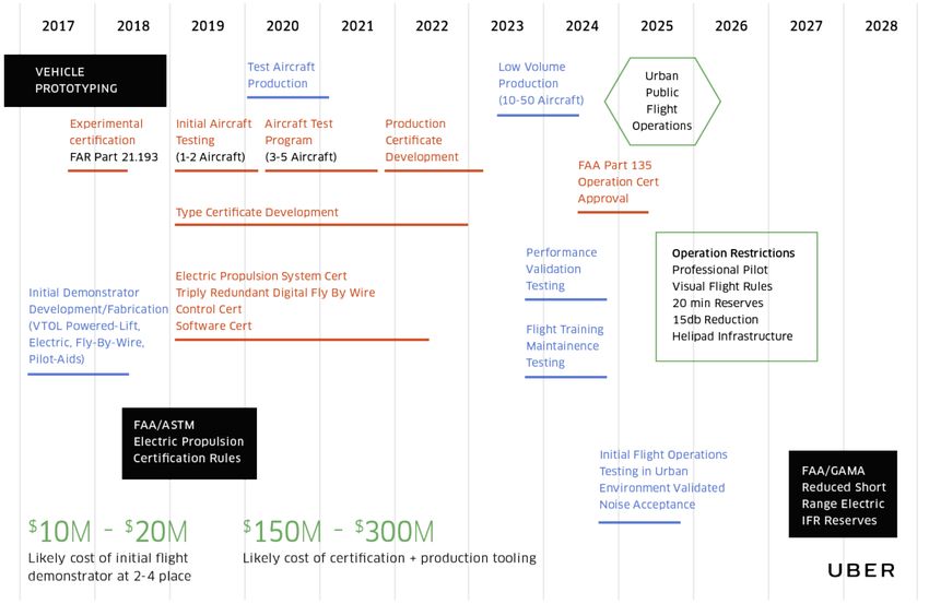
Contents
 9.3 Materials selection . . . . . . . . . 42
List of Figures i 9.4 Fuselage section . . . . . . . . . . 44
 9.5 Wing . . . . . . . . . . . . . . . . 48
List of Tables iii
 9.6 Structure Conclusion . . . . . . . . 53
Nomenclature iii 10 Stability analysis . . . . . . . . . . . . . . 54
 10.1 Pitching moment stability . . . . . 54
1 Mistral Air Taxi design 1 10.2 Dynamic analysis . . . . . . . . . . 56
 1 Introduction . . . . . . . . . . . . . . . . . 1 10.3 Yaw controls . . . . . . . . . . . . 59
 1.1 Context . . . . . . . . . . . . . . . 1 11 Aircraft performance . . . . . . . . . . . . 60
 2 Mission description and design objectives . 2 11.1 Segment Analysis . . . . . . . . . . 61
 2.1 State-of-the-art of VTOL technology 2 11.2 Reserve mission . . . . . . . . . . 71
 2.2 Mission and RFP analysis . . . . . 3 11.3 Global Results . . . . . . . . . . . 71
 3 Methodology . . . . . . . . . . . . . . . . 4 11.4 Point Performances . . . . . . . . . 72
 4 Design selection . . . . . . . . . . . . . . . 5 12 Mechanism . . . . . . . . . . . . . . . . . 74
 5 Weight estimation . . . . . . . . . . . . . . 6 13 Trade-off study . . . . . . . . . . . . . . . 78
 5.1 First mass estimation . . . . . . . . 6 13.1 Wing characteristics . . . . . . . . 78
 5.2 Subsequent mass estimations . . . . 7 14 Cost analysis . . . . . . . . . . . . . . . . 79
 6 CAD . . . . . . . . . . . . . . . . . . . . . 7 14.1 Method used . . . . . . . . . . . . 80
 14.2 Market size and potential . . . . . . 80
 7 Components design . . . . . . . . . . . . . 9
 14.3 Development and manufacturing costs 81
 7.1 Fuselage . . . . . . . . . . . . . . 9
 14.4 Break-even analysis . . . . . . . . 82
 7.2 Wing . . . . . . . . . . . . . . . . 11
 14.5 Operating costs . . . . . . . . . . . 84
 7.3 Canard . . . . . . . . . . . . . . . 14
 14.6 Comparison with other means of
 7.4 Control surfaces . . . . . . . . . . 15
 transport . . . . . . . . . . . . . . 84
 7.5 Propulsion & energy systems . . . . 16
 15 Conclusion . . . . . . . . . . . . . . . . . 86
 7.6 Electronic system . . . . . . . . . . 20
 7.7 Landing gear . . . . . . . . . . . . 24 Bibliography 87
 7.8 Autonomous system . . . . . . . . 26
 8 Aerodynamic study . . . . . . . . . . . . . 30 A Appendix 90
 8.1 Tranair . . . . . . . . . . . . . . . 30 1 Batteries . . . . . . . . . . . . . . . . . . . 90
 8.2 Drag analysis. . . . . . . . . . . . . 33 2 Dynamic analysis . . . . . . . . . . . . . . 91
 9 Structure design . . . . . . . . . . . . . . . 37 3 Autonomous system cost breakdown . . . . 91
 9.1 Flight Envelope . . . . . . . . . . . 37 4 Cost comparison between different means
 9.2 Loading . . . . . . . . . . . . . . . 39 of transport . . . . . . . . . . . . . . . . . 92

List of Figures
 1.14 Side view of the fuselage showing the di-
 1.1 Mobility mix shift. Comparison of Boston, mensions. . . . . . . . . . . . . . . . . . . 10
 Berlin and Shanghai. . . . . . . . . . . . . 1 1.15 Cabin interior view. . . . . . . . . . . . . . 11
 1.2 CityAirbus . . . . . . . . . . . . . . . . . 3 1.16 Wing airfoil NACA2412. . . . . . . . . . . 12
 1.3 Lilium Jet . . . . . . . . . . . . . . . . . 3 1.17 Comparison of the 3D lift coefficient and the
 1.4 Aurora Passenger Air Vehicle . . . . . . . 3 2D lift coefficient. . . . . . . . . . . . . . . 13
 1.5 General view of a typical mission of the E- 1.18 Canard airfoil NACA6412. . . . . . . . . . 14
 VTOL. . . . . . . . . . . . . . . . . . . . . 3 1.19 Top and lateral views of the elevons. . . . . 16
 1.6 Schematic of the general methodology 1.20 Engines power for sizing mission. . . . . . 19
 adopted for the conceptual design phase. . . 5 1.21 Payload range diagram. . . . . . . . . . . . 22
 1.7 Percentage of gross weight. . . . . . . . . . 7 1.22 Propulsion system on the canard. . . . . . . 22
 1.8 Realistic view of Mistral Air Taxis. . . . . . 8 1.23 Flight (left) and take-off (right) configura-
 1.9 Side, front and top view of the Mistral Air tions for wing engines. . . . . . . . . . . . 23
 Taxi. . . . . . . . . . . . . . . . . . . . . . 8 1.24 Views and locations for wing propulsion. . 23
 1.10 Top view . . . . . . . . . . . . . . . . . . 9 1.25 Landing gear geometric parameters. . . . . 24
 1.11 Lateral view . . . . . . . . . . . . . . . . . 9 1.26 Landing gear geometric parameters. . . . . 25
 1.12 Position of CG (inches) . . . . . . . . . . . 9 1.27 Certification and validation schedule pro-
 1.13 Proposed design for the main cabin. . . . . 10 posed by Uber[40]. . . . . . . . . . . . . . 27

 i

1.30 Autonomous system architecture. In yellow 1.59 The red and the blue lines represent the peak
 the aircraft, in green the public ATC and in power required by the engines for the transi-
 grey the other flying objects. . . . . . . . . 29 tion phase, expressed in percentage with re-
1.31 Airplane lift curve from Tranair and from spect to the hover nominal power. In yellow
 the conceptual design. . . . . . . . . . . . . 31 is presented the energy requirement trend
1.32 Airplane drag polar from Tranair and from with respect to the total transition period. . 64
 the conceptual design. . . . . . . . . . . . . 31 1.60 Lift produced at the end of the transition pe-
1.33 Section lift coefficient along the half-span of riod as function of the transition period. . . 64
 the wing, in cruise, with and without the ef- 1.61 Wing, canard thurst (magnitudes) and lift
 fect of the canard. . . . . . . . . . . . . . . 32 profile over the transition phase. . . . . . . 65
1.34 Wing lift curve with and without the canard. 32 1.62 Wing engine thrust and energy consumption
1.35 Section lift coefficient along the half-span of as a function of the desired vertical velocity. 66
 the canard, at cruise, with and without the 1.63 Wing engine thrust and energy consumption
 effect of the wing. The reference chord is cw . 33 as a function of the cruise altitude. . . . . . 66
1.36 Division of the drag. . . . . . . . . . . . . 35 1.64 Wing engine thrust and energy consumption
1.37 Division of the different type of drag. . . . 35 as function of the cruise velocity. . . . . . . 67
1.38 Airplane drag polars obtained from Tranair 1.65 Thrust and energy requirement with respect
 and from empirical methods (advanced and to cruise velocity. . . . . . . . . . . . . . . 67
 conceptual design). . . . . . . . . . . . . . 36 1.66 Maximum vertical velocities as function of
1.39 Design cruise (blue) and dive (dashed blue) cruise velocity. . . . . . . . . . . . . . . . 67
 velocities (TAS) as a function of the altitude. 38 1.67 Thrust and energy requirement with respect
1.40 Maneuver (red) and gust (blue) envelopes of to desired descending velocity at VDescent . . 68
 the Mistral Air Taxi. . . . . . . . . . . . . . 38 1.68 Energy consumption as function of de-
1.41 Schematics of the aerodynamic forces act- transient period. . . . . . . . . . . . . . . . 68
 ing on the aircraft. . . . . . . . . . . . . . . 39 1.69 Wing and canard engine thrust profile (mag-
1.42 Position of stringers (red circles). The cross nitude) as function of de-transient period. . 68
 red is the centroid of the fuselage section. . 47 1.70 Wing and canard engine thrust (magnitude)
1.43 Mesh of the fuselage structure. . . . . . . . 47 profile during breaking. . . . . . . . . . . . 70
1.44 Deformation of the fuselage under maxi- 1.71 Trend of the different drags during the
 mum loading at point C of the flight envelope. 48 breaking manoeuvre with the horizontal ve-
1.45 Position of stringers and flanges (red circles) locity profile (in purple). . . . . . . . . . . 70
 and spars (blue). The red cross is the cen- 1.72 Relation between sizing mission energy and
 troid of the wing section. . . . . . . . . . . 51 reserve mission energy. . . . . . . . . . . . 71
1.46 Internal structure of the wing as studied us- 1.73 Partition of energy consumption during the
 ing NX. . . . . . . . . . . . . . . . . . . . 51 sizing mission. . . . . . . . . . . . . . . . 72
1.47 Mesh of the wing structure. . . . . . . . . . 51 1.74 Phases time period. . . . . . . . . . . . . . 72
1.48 Maximal principal stresses on the structure 1.75 Phases covered distance. . . . . . . . . . . 72
 of the wing under maximum loading at point 1.76 Thrust profiles (absolute value of thrust)
 B of the flight envelope. . . . . . . . . . . . 53 during transitions; dashed lines represent
1.49 Deflection of the wing under maximum the thrusts profile for sizing mission, solid
 loading at point B of the flight envelope. . . 53 lines are the "high and hot" ones. . . . . . . 74
1.50 Important lever arms used for the pitching 1.77 Mechanism block diagram. . . . . . . . . . 75
 moment stability. . . . . . . . . . . . . . . 54 1.78 Engine motion diagram: from the top to the
1.51 Schematic of the elevator. . . . . . . . . . . 55 bottom 1) position as function of time 2) an-
1.52 Representation in the complex plane. . . . . 57 gular velocity as function of time 3) angular
1.53 Lateral velocity v perturbation evolution. . . 59 acceleration as function of time. . . . . . . 76
1.54 Roll angle φ and roll angular velocity p evo- 1.79 Tilting system installation. . . . . . . . . . 77
 lution. . . . . . . . . . . . . . . . . . . . . 59 1.80 E-VTOL market size evolution and regional
1.55 Yaw angle ψ and yaw velocity r evolution. split between the year 2025 and 2035 from
 The dotted line represent the commanded [59]. . . . . . . . . . . . . . . . . . . . . . 80
 yaw angle . . . . . . . . . . . . . . . . . . 60 1.81 Comparison of the labor cost in different
1.56 Segment analysis flow path. . . . . . . . . . 61 countries [60]. . . . . . . . . . . . . . . . . 81
1.57 Thrust behaviour with respect to RPM 2 of 1.82 The development cost in millions of dollars
 the wing engines. . . . . . . . . . . . . . . 62 as a function of units produced. . . . . . . . 83
1.58 Approximation of the thrust profile as func- 1.83 Fixed cost, total cost and revenue as a func-
 tion of RPM 2 for wing engines for a flight tion of the number of units produced. . . . . 83
 velocity of v = 134mph. . . . . . . . . . . 62 1.84 Trip between New York and New Haven[61]. 85

 ii
1.85 Trip between Newark and Kennedy airports A.2 Autonomous system cost breakdown [70]. . 91
 [61]. . . . . . . . . . . . . . . . . . . . . . 85 A.3 Volumetric energy density trends.[69] . . . 92
 A.1 Strengths and weaknesses of lead-acid, A.4 Power density trends.[69] . . . . . . . . . . 92
 NiMH and NiCd batteries. . . . . . . . . . 90 A.5 BLADE Airport lines in New York. . . . . 93

List of Tables
 1.23 Allowed configurations. . . . . . . . . . . . 55
 1.1 Table of the main concept of E-VTOL air-
 1.24 controls fixed and free stability margins . . 55
 craft currently in development. . . . . . . . 2
 1.25 Characteristics of the vibration modes of the
 1.2 E-VTOL configurations. . . . . . . . . . . 3
 aircraft. . . . . . . . . . . . . . . . . . . . 58
 1.3 Table of some of the aircraft considered for
 1.26 Aircraft mode of vibration under LQI con-
 the first mass estimation. . . . . . . . . . . 6
 trol action. . . . . . . . . . . . . . . . . . . 59
 1.4 Complete weight breakdown. . . . . . . . . 7
 1.27 Hovering results. . . . . . . . . . . . . . . 63
 1.5 Features of the wing. . . . . . . . . . . . . 14
 1.28 Transient results. . . . . . . . . . . . . . . 65
 1.6 Summary of the main parameters of the ca-
 nard. . . . . . . . . . . . . . . . . . . . . . 15 1.29 Climb results for minimum requirements. . 66
 1.7 Characteristics of the elevons. . . . . . . . 16 1.30 Cruise results. . . . . . . . . . . . . . . . . 67
 1.8 Global propellers characteristics. . . . . . . 18 1.31 Descent results. . . . . . . . . . . . . . . . 68
 1.9 Comparison between different electric motors. 19 1.32 De-transient results. . . . . . . . . . . . . . 69
 1.10 Electric motors characteristics and operat- 1.33 Breaking results. . . . . . . . . . . . . . . 70
 ing points for takeoff and cruse. . . . . . . 20 1.34 Landing results. . . . . . . . . . . . . . . . 70
 1.11 Characteristics of the batteries. The total 1.35 De-transient results. . . . . . . . . . . . . . 71
 stands for 2 wing’s battery pack and 1 ca- 1.36 Hovering results. . . . . . . . . . . . . . . 73
 nard’s battery pack . . . . . . . . . . . . . 21 1.37 Transient results. . . . . . . . . . . . . . . 74
 1.12 Landing gear Placement . . . . . . . . . . 25 1.38 Engine dynamics parameter for a cluster of
 1.13 Landing gear loads. . . . . . . . . . . . . . 25 seven engines. . . . . . . . . . . . . . . . . 77
 1.14 Tire selection and specifications. . . . . . . 26 1.39 From the motor and transmission selection,
 1.15 Contributions of drag component at cruise. . 34 sizes and system parameter are presented. . 77
 1.16 Drag coefficients in cruise conditions evalu- 1.40 Trade-off analysis for the aspect ratio of the
 ated via Tranair and via empirical methods. 37 wing. The values represent the % of varia-
 1.17 Critical points of the flight envelope and tion with respect to the reference configura-
 aeronautical loads. . . . . . . . . . . . . . 40 tion obtained after the design. . . . . . . . . 79
 1.18 Structural loading on the fuselage for the 1.41 Breakdown of the certification cost for the
 critical points of the flight envelope. . . . . 41 aircraft. . . . . . . . . . . . . . . . . . . . 81
 1.19 Structural loading at the wing root for the 1.42 Breakdown of the total cost for one aircraft. 82
 critical points of the flight envelope. . . . . 42 1.43 Breakdown of the operating cost per aircraft. 84
 1.20 Mechanical properties of the selected com- 1.44 Comparison of different means of transport
 posite. . . . . . . . . . . . . . . . . . . . . 44 in terms of travel time and cost for a trip
 1.21 Values of the main structural elements ob- from New York to New Haven. . . . . . . . 85
 tained with the analytical study. . . . . . . . 51 1.45 Comparison of different means of transport
 1.22 Values of the main structural elements ob- in terms of travel time and cost for a trip
 tained through finite element analysis. . . . 52 from Newark to Kennedy Airport. . . . . . 85

Nomenclature
List of acronyms ATM Air Traffic Management

AC Alternating Current BEM Blade Element Method

ADS-B Automatic Dependent Surveillance-Broadcast BEMT Blade Element Method Theory

AIAA American Institute of Aeronautics and Astronautics BLDC BrushLess DC

ATC Air Traffic Control BMI Bismaleimide

 iii
CAD Computer - Aided Design NASA National Aeronautics and Space Administration
CFD Computational Fluid Dynamics ODM On-Demand Mobility

CG Center of Gravity PAV Passenger Air Vehicle

CPI Consumer Price Index PEEK Polyether Ether Ketone

CPU Central Processing Unit RFP Request For Proposal

CS Certification Specifications RHS Right Hand Side
 RPM Rotations Per Minute
DC Direct Current
 RTDC Research Development Testing and Certification
DEP Distributed Electric Propulsion
 SAE Society of Automotive Engineers
DGPS Differential Global Positioning System
 SMPM Synchronous Motor Permanent Magnet
DOF Degree Of Freedom
 SPO short Period oscillations
E-VTOL Electric Vertical Takeoff and Landing
 STOL Short Takeoff and Landing
EIPF Earth Inertial Reference Frame
 TAS True Airspeed
EIS Entry Into Service
 TRL Technology readiness level
EoM Equation of Motion
 UAM Urban Air Mobility
EV Electric Vehicle
 UN United Nations
FAA Federal Aviation Administration
 USA United States of America
FAR Federal Aviation Regulation UV Ultra Violet
FEM Finite Element Method VFR Visual Flight Rules
FWD Forward VTOL Vertical Takeoff and Landing
GA General Aviation List of symbols
GNSS Global Navigation Satellite System α Angle of attack ◦

GPS Global Position System ẍ Acceleration on EIRF x-axis f t/s2

GPU Graphics Processing Unit ÿ Acceleration on EIRF y-axis f t/s2
 δ Maximum deflection ◦
HSI Hyperspectral Imaging Systems
IFR Instrument Flight Rules η Engine efficiency -

ISA International Standard Atmosphere γ Climb angle red

LHS Left Hand Side λ Taper -
 Ω Angle between hovering pointing direction of en-
LQI Linear Quadratic Integral control
 gine and the axis of the propeller rad
MAC Mean aerodynamic chord
 ρ Air density lb/ f t 3
MGTOW Maximum Gross Take-Off Weight σ Duct expansion ratio -
MSI Multispectral Imaging Systems A Disk actuator area of the ducted fan f t2
MSL Mean Seal Level a The slope of the 3D lift -
MTOW Maximum Take-Off Weight AR Aspect ratio -
MV Medium Voltage b Span ft
NACA National Advisory Committee for Aeronautics Bdens Battery density KW /kg

 iv
Bdens Battery energy density W h/kg lc Distance between CG and the point of application
 of canard thrust along roll axis ft
c Chord ft
 lc p Distance between CG and the aerodynamic center
CD Drag Coefficient - of canard along roll axis ft
CL Lift Coefficient - lw Distance between CG and the point of application
 of wing thrust along roll axis ft
CD,0 Zero-Lift Drag Coefficient -
 lw p Distance between CG and the aerodynamic center
Cl,α airfoil slope of the lift curve rad −1 of wing along roll axis ft
CL3D 3D lift coefficient - M Mass of battery packs W /kg
 peak
CLα Lift coefficient derivative with respect to the angle P Power required per engine KW
 of attack rad −1
 Pa Available power KW
CMα,c/4 Moment coefficient at the quarter chord -
 Pr Required power KW
D Total drag of the aircraft lb f
 Ppeak Peak specific power W /kg
d Distance covered during certain phase ft
 PT OT Power required by the engines W /kg
De Drag due to engines movable part lb f
 S Surface f t2
Ds Drag due to Airbreakers ft
 T Thrust lb f
E Energy KW
 V Aircraft velocity f t/s
e Oswald efficiency factor −
 W Total weight of aircraft lb
Emission Mission energy Wh
 xAC Chordwise coordinate of the aerodynamic center in
hc Distance between CG and the point of application
 List of subscript
 of canard thrust along yaw axis ft
 c Canard
hw Distance between CG and the point of application
 of wing thrust along yaw axis ft e Elevons
i Incidence angle ◦
 s Spoiler
L Total lift of the aircraft lb f w Wing

 v
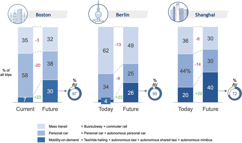
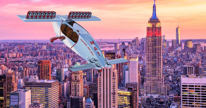
1 Mistral Air Taxi design

1 Introduction

In response to the Request for Proposal (RFP) emitted by the American Institute of Aeronautics and Astronautic (AIAA)

in the context of the 2018-2019 graduate team aircraft competition, we, the members of the Huggy’s bird team are proud to

present the Mistral Air Taxi. The Mistral Air Taxi is a four-seater Electric Vertical Takeoff and Landing aircraft (E-VTOL).

 This report is the work of a team of eight students who are enrolled in the first year of the Master’s degree in Aerospace

Engineering at the University of Liège in Belgium. This project is part of the official curriculum and was supervised by

several faculty members, including professors L. Noels and G. Dimitriadis.

 The report starts with an analysis of the E-VTOL aircraft market and a presentation of the design methodology. Then,

the possible configurations are discussed. The core of the report presents the design of the different components of the

aircraft. The performance is also studied into details. Lastly, an economical study of the aircraft is performed.

1.1 Context

According to the figures presented in a 2014 United Nations’ (UN) report on world’s urbanization [1], more than half (54

%) of the world population lives in a urban environment. In North America, this figure even rises to 82 %. It is projected

that by 2050, 66 % of the world’s population will be living in an urban area. This will inevitably pose great challenges

in terms of mobility. Already today, it is estimated that 64 % of the kilometers travelled each year take place in urban

areas. This number is only expected to rise as the urban population increases. It is in this context that companies like Uber

Elevate are developing new services for unscheduled on-demand air transportation [2][3]. This new kind of service has a

great commercial potential. Researches conducted in different cities have shown that airport and end-to-end city transfers,

as well as daily commuting are the most promising segments [3]. Future transportation trends are shown in Fig. 1.1. A

decrease of personal and mass transit is expected, favoring an uberisation of the transport sector and enhancing the urban

mobility mix where E-VTOL aircraft have a clear advantage: movement in 3D space [4].

 Figure 1.1: Mobility mix shift. Comparison of Boston, Berlin and Shanghai.

 1
2. MISSION DESCRIPTION AND DESIGN OBJECTIVES CHAPTER 1. MISTRAL AIR TAXI DESIGN

 Moreover, the most recent improvements in electric motors and battery technology have prompted new interest in

all-electric aircraft propulsion. Even though the power requirements for longer trips or airliners are far from being met,

all-electric propulsion could be applied in the context of smaller vehicles performing shorter trips. These smaller vehicles

would be well suited for urban mobility [5].

 In consideration of the above, several companies have started designing new concepts of electric aircraft that could

meet the future demand for urban air mobility. Currently, no concept of E-VTOL has yet been commercialised. Some of

the most notable project are presented in Table 1.1. It is in the same context that the AIAA has emitted the RFP for the

design of an E-VTOL aircraft.

 Name Company # of passengers Status

 Lilium jet Lilium GmbH 2 ( expected 5 ) undergoing test flights

 A3 Vahana Airbus 2 undergoing test flights

 Aurora Passenger Air Vehicle (PAV) Aurora (Boeing) 2 undergoing test flights

 Bartini flying car Bartini 2 or 4 under development

 DreamMaker Embraer 4 ( +1 pilot) under development

 KittyHawk Cora 2 undergoing test flights

 CityAirbus Airbus Helicopter 4 under development

 Volocopter 2X Volocopter 2 undergoing testing

 Table 1.1: Table of the main concept of E-VTOL aircraft currently in development.

2 Mission description and design objectives

2.1 State-of-the-art of VTOL technology

The purpose of the conceptual design is to define an initial configuration for the aircraft. In order to do so, a review of the

state-of-the-art of E-VTOLs is carried out. One of the main problems to tackle when designing an E-VTOL is the vertical

takeoff and landing capabilities. Currently, there exist very few aircraft that are capable of such a feat. Example of VTOL

aircraft include the F35-B or the V-22 Osprey.

 There are basically three ways to tackle this issue: either the aircraft is built like an helicopter and the lift is produced

exclusively by rotors, or the lift is produced by wings during the flight. In the second case, the takeoff lift is either

produced by a set of fixed motors different from the motors producing the thrust (lift + cruise), or by the same engines that

will produce the thrust during the flight (vectored thrust). In the latter case, the motors must tilt to provide thrust. Each

configuration has its own advantages and disadvantages, summarized in Table 1.2.

 2
2. MISSION DESCRIPTION AND DESIGN OBJECTIVES CHAPTER 1. MISTRAL AIR TAXI DESIGN

 Classification Illustration (+) Benefits (-) Disadvantages

 Compactness Energy consumption in cruise

 Wingless Efficiency in hovering Complex

 Figure 1.2: CityAirbus

 Reduced Mass Complex manoeuvres

 Vectored thrust VTOL + STOL Tilting mechanism

 Figure 1.3: Lilium Jet

 Simplicity Mass

 Lift + Cruise VTOL + STOL Unused propellers

 No tilting mechanism Drag

 Figure 1.4: Aurora Passenger Air Vehicle

 Table 1.2: E-VTOL configurations.

2.2 Mission and RFP analysis

 60 sm

 Cruise

 Descent
 Climb
 Hover min 1.500 ft Hover
 Takeoff Landing

 Departure Destination

 Figure 1.5: General view of a typical mission of the E-VTOL.

The general requirements to be met by the aircraft are defined in the RFP of the AIAA and are summarized below:

 • Must be able to transport 4 people ( 1 pilot and 3 passengers or 4 passengers), each person weighing 180 lb (+20 lb

 of luggage for each passengers);

 3
3. METHODOLOGY CHAPTER 1. MISTRAL AIR TAXI DESIGN

 • Must be able to take off and land vertically, as well as hover;

 • Minimum cruising altitude is 1,500 ft;

 • Average speed during cruise and climbing must be at least 150 mph;

 • Maximum speed of at least 176 mph at altitudes between 1,500 and 3,000 feet;

 • Must have a minimum range of 60 statute miles;

 • In case a landing is aborted, the aircraft must be able to divert to an alternate landing spot located at a distance of 2

 statute miles from the original location;

 • Average climb rate not to exceed 500 feet/min;

 • Descent rate not to exceed 1,000 feet/min;

 • FAA part 23 airworthiness requirements must be met;

 • Capable of VFR and IFR flight with autopilot;

 • Can be fully autonomous.

3 Methodology

The conceptual design of the aircraft begins with a careful study of the requirements defined in the proposal, as well as a

market review. Some key parameters of the airplane are then fixed. Empirical formulas can be used to compute quantities

such as the mass, the wing area or the required thrust. However, due to the interdependence between each quantity, this

work is an iterative process. It is therefore not possible to obtain a stable and converged configuration in one iteration. The

general methodology followed during the conceptual design is described in Fig. 1.6 and was heavily inspired by [6] and

[7].

 As illustrated in the flow chart, the first step is to decide on a configuration: canard or tail, high wing or low wing,

propellers or ducted fans. Then a first estimation of the mass is obtained as described in Section 5. Using the knowledge

of that first mass, every component of the aircraft (fuselage, wing, tail, propulsion) can be sized. Once every component

has been computed, a new total mass is calculated. If the difference between the previous mass and this new mass is small

enough, stability and performances can be verified. Otherwise, the components of the aircraft must be recomputed using

the last mass computed. This process must be repeated until convergence.

 In the second part of the project, each component is studied with more care. Advanced tools like Tranair or Siemens

NX are used to obtain more precise results for certain parts of the design. Advanced empirical correlations are also used to

perform the drag and performance analysis.

 4
4. DESIGN SELECTION CHAPTER 1. MISTRAL AIR TAXI DESIGN

 INPUTS MTOW estimation C.G. assessment

 Request for proposal
 Stable ?
 Fuselage design NO
 State of the art
 Wing sizing YES

 Configuration Empennage
 Performance OK ?
 Propulsion NO
 YES
 Lift and Drag
 OUTPUTS

 CAD
 Polars
 ΔW < ε Stability margins
 NO YES

 Figure 1.6: Schematic of the general methodology adopted for the conceptual design phase.

4 Design selection

The initial configuration is to be used as starting point to evaluate all the components. The choices made are justified

hereunder:

Distributed electric propulsion

According to ONERA’s study [8], the use of Distributed Electric Propulsion (DEP) has some potential especially in all-

electric powered airplanes for civil transportation. This concept, which is compliant with the CS23 regulations, has been

retained for its promising performances.

Wing & Canard

The wingless configuration was discarded as the energy consumption was considered to be too important. In addition,

instead of a conventional tail and wing design, it was decided to use a canard and wing configuration. The canard con-

figuration has the obvious advantage of placing the elevons in an undisturbed flow [7]. This makes the response of those

control surfaces more predictable, which is a clear advantage as the aircraft is autonomous. Furthermore, in opposition to

the lift of a tail which is oriented downwards, the canard lift is pointing upwards, counteracting gravity alongside with the

wing. This results in lower wing loading and lower drag [7].

 A high wing configuration was preferred over more traditional designs. One of the advantages of this configuration is

that the access to the passenger cabin is not obstructed by the wing. Boarding and unboarding is consequently easier and

faster. Moreover, high wings are also better in terms of stability. The geometrical parameters of the wing will be discussed

in a later section.

 5
5. WEIGHT ESTIMATION CHAPTER 1. MISTRAL AIR TAXI DESIGN

Vectored Thrust

Among the different propulsion strategies, vectored thrust is preferred as it fully exploits the thrust contribution of each

engine throughout the whole mission. The way this principle takes place in the Mistral Air Taxi is a compromise with the

choice of a canard configuration; canard structure stiffness avoid distributed tilting propulsion to be placed along the span,

so it’s decided to fix engines directly on the fuselage at the canard roots.

Differential thrust

Traditionally, yaw control is achieved by installing a fin on the aircraft. Adding a fin would make the aircraft heavier and

therefore reduce its efficiency. Moreover, it would require the fuselage to be longer to have a sufficient lever arm. It was

decided here not to use a fin. Rather yaw control will be achieved through a differential thrust system.

Autonomous system

Machine learning and artificial intelligence in the oncoming years will reshape the way people travel. It will contribute to

improve safety and security, reduce jams and time loss, thus improving resource management and time allocation, but not

without risk, uncertainties or controversies. Equipping the aircraft with an autonomous system is mandatory [9] [10].

5 Weight estimation

5.1 First mass estimation

A first estimation of the total mass is obtained by studying similar concept of aircraft. The data used for this first estimation

was found online through extensive research [11]. A summary can be found in Table 1.3.

 Name Number of passengers Mass per passengers [lb]

 Lilium jet 2 705.48

 Transcend Air Vy 400 6 1,165

 Hop Fly Ventury 4 447.54

 Bartini flying car 4 606.27

 XTI Aircraft Trifan 600 6 883.33

 A3 Vahana 2 897.28

 Initial design of an E-VTOL in [12] 2 1,106.72

 Initial design of an E-VTOL in [12] 4 974.4

 Table 1.3: Table of some of the aircraft considered for the first mass estimation.

 The mass of each aircraft has been divided by the number of passengers in order to obtain comparable values. The 20 %

 6
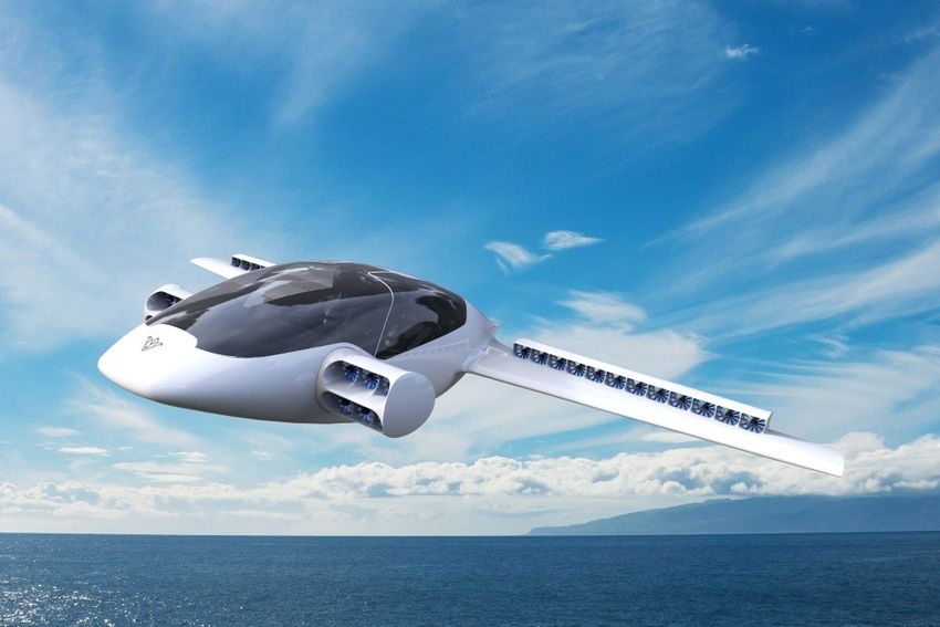
6. CAD CHAPTER 1. MISTRAL AIR TAXI DESIGN

lowest values were removed and the remaining masses were averaged to calculate an average aircraft mass per passengers.

Adding a safety margin of 10 %, it was eventually found that the initial starting mass was 3,307 lbs.

5.2 Subsequent mass estimations

The mass calculated in the previous section was used as a starting point for the design. During the following parts of the

project, the mass of the different components were primarily estimated using the empirical formulas found in Raymer’s

book [7]. The mass of the wing was not calculated using the formulas from the previous source. Rather, it was computed

using the formulas found in [13].

 The total weight of the aircraft is simply obtained by summing the mass of the different parts. Table 1.4 presents a

breakdown of the mass of all the subparts of the aircraft while Fig 1.7 provides a visual breakdown of the total mass. The

maximum takeoff weight of the aircraft is found to be about 3,470 lb.

 Weight breakdown [lb]

 Fuselage 295

 Wing 268

 Canard 125
 11%
 Control systems 41 20%
 5%
 Landing gear 165

 Autopilot 154 5%

 Engine rotation mechanism 54

 Engines 291
 13%
 Nacelles 77
 24%
 Batteries 649

 Electrical 180

 Avionics 184 22%
 Battery
 Furniture 136 Payload
 Fuselage and Wings
 Engines
 Air-conditioning 50 Autopilot and Avionics
 Power electronics
 Payload 800 Other empty weight

 Total 3,470
 Figure 1.7: Percentage of gross weight.
 Table 1.4: Complete weight breakdown.

6 CAD

The aim of the CAD is to give a realistic view of the aircraft and to check the integration of each subsystem. It is also

useful to calculate a better approximation of the mass, the position of CG and the inertias of the aircraft.

 7
6. CAD CHAPTER 1. MISTRAL AIR TAXI DESIGN

 Figure 1.8: Realistic view of Mistral Air Taxis.

 Figure 1.9: Side, front and top view of the Mistral Air Taxi.

 The position of each subsystem is shown in Fig. 1.10 and 1.11 while the position of the center of gravity at its maximum

take off weight is shown in the Fig. 1.12. The electrical systems are supposed to be distributed so they are not shown in

these drawings.

 8
7. COMPONENTS DESIGN CHAPTER 1. MISTRAL AIR TAXI DESIGN

 Figure 1.10: Top view

 Figure 1.11: Lateral view Figure 1.12: Position of CG (inches)

7 Components design

7.1 Fuselage

It could be argued that the fuselage is the key element of any aircraft as it will carry the useful loads. The design of

the fuselage is therefore of the utmost importance. The dimensions of the main cabin must be chosen in order to offer

maximum comfort to the passengers. Once the main cabin has been designed, the rest of the fuselage must be designed in

order to accommodate the different required systems.

 9
7. COMPONENTS DESIGN CHAPTER 1. MISTRAL AIR TAXI DESIGN

Main cabin design The main cabin design is of paramount importance in the overall design process. A balance between

passenger comfort and performance must be found. A very large cabin would provide more comfort to the passengers but

it would result in higher drag. Roskam [14] gives the size of the seats and aisles as a function of the travel class. In order

to provide the best customer experience, it was decided to take the highest possible values. The proposed cabin design is

presented in Fig. 1.13.

 Figure 1.13: Proposed design for the main cabin.

Fuselage length Besides the main cabin, there are no other parts of the fuselage that must be accessible to passengers

(since the flights will be very short, there are no lavatory and no galley). There must however be a luggage compartment

at the rear of the aircraft and room to accommodate the auto-pilot and air-conditioning systems at the front of the fuselage.

With those constraints in mind, the fuselage length was determined through successive stability analysis. The final design

is presented in Fig. 1.14.

 Figure 1.14: Side view of the fuselage showing the dimensions.

 10
7. COMPONENTS DESIGN CHAPTER 1. MISTRAL AIR TAXI DESIGN

 Figure 1.15: Cabin interior view.

7.2 Wing

The wing produces a large portion the required lift for the airplane to fly. As such, its design is a key step in the conception

procedure of a new aircraft. The wing is firstly designed from an aerodynamic point of view using empirical formulas.

Then, in the preliminary design, its aerodynamic properties will be reassessed with Tranair along with the loads acting on

it, it order to properly design it from a structural point of view.

 In order to be consistent throughout the design process, choices have been made. They are detailed hereunder.

 • Cruise Mach number: the RFP states that the average cruising speed should be 150 mph. Flying at an altitude of

 1,500 feet, it leads to a flight Mach number of 0.1979 .

 • Design lift coefficient: using the simple relationship linking the lift coefficient and the drag coefficient:

 CL2
 CD = CD,0 + (1.1)
 eπAR

 it could be shown that the optimal lift coefficient for the wing is in the range [0.75 - 1]. However, using such a high

 lift coefficient would lead to a very high wing loading, which would result in a bigger and heavier structure. It was

 therefore decided here to favor a lower wing loading over optimal aerodynamic performances. The lift coefficient

 must then lie in the interval [0.3 - 0.45]. Based on the results presented in [6], conservative values were chosen for e

 and CD,0 : e = 0.75 and CD,0 = 0.03.

 • Airfoil selection: as mentioned previously, the flight Mach number is subsonic. This means that simple 4-digits

 11
7. COMPONENTS DESIGN CHAPTER 1. MISTRAL AIR TAXI DESIGN

 NACA profile can be used. The design lift coefficient of the airfoil should match the flight lift coefficient to reduce

 the drag. The NACA 2412 was selected. This airfoil has a thickness ratio of 12 and a max camber located at 40% of

 its chord. Its design lift coefficient is in the range [0.3 - 0.4] and therefore matches our chosen lift coefficient.

 0.3

 0.2

 0.1

 0

 -0.1

 -0.2

 -0.3

 0 0.1 0.2 0.3 0.4 0.5 0.6 0.7 0.8 0.9 1

 Figure 1.16: Wing airfoil NACA2412.

 • Aspect ratio: The aspect ratio is defined as follows:

 b2
 AR = (1.2)
 Sw

 In [7], the recommended aspect ratio for general aviation aircraft is around 7.6 - 7.8, depending on the number of

 engines. It was decided to round up this value to 8 for this aircraft.

 • Taper: in this case, a tapered wing is not required because although tapered wings usually have lower drag, they are

 harder to manufacture.

 Using the same method as in Section 14 to determine the cost, it appears that only the tooling costs are influenced

 by the fact that the wing is tapered or not. Using the method described in the aforementioned section, the additional

 tooling cost associated with tapered wings is estimated to be 5,000,000 $.

 Moreover, using the method described in Section 8, the drag for different tapers is evaluated. In the end, the drag

 for an ideal taper value (λ = 0.45 according to [7]) is found to be 98 % of the drag of an untapered wing. This has

 virtually no effects on the weight of the battery, the range or the perfomance of the aircraft.

 In this case, the benefit of lower drag was considered to be too reduced to be profitable. Easier and cheaper manu-

 facturing were preferred to aerodynamic performances.

 • Other geometric parameters: in order to keep the wing as simple as possible, it was decided that the twist angle

 would be zero and that there would not be a dihedral.

 12
7. COMPONENTS DESIGN CHAPTER 1. MISTRAL AIR TAXI DESIGN

Methodology The first step when designing a wing is to compute its 3D lift coefficient. Its slope can be computed from

the airfoil lift slope (computed using X f oil) using the following formula [15]:

 cl,α
 CL,α = 0.995 cl,α (1.3)
 EJ + πAR

 2λ
where EJ = 1 + AR(1+λ ) is Jone’s correction. The 3D lift coefficient obtained using this formula is shown as a function of

the angle of attack in Fig. 1.17.

 40
 3D - =1
 2D
 30

 20

 10
 CL

 0

 -10

 -20

 -30

 -40
 -6 -4 -2 0 2 4 6
 [°]

 Figure 1.17: Comparison of the 3D lift coefficient and the 2D lift coefficient.

 Through successive stability analysis, it was determined that the wing would sustain 63 % of the lift (and therefore, the

canard 37%). Then assuming that in cruise the lift of the wing must equal 63 % of the weight, we can write:

 1
 L = 0.63W = V 2CL ρSw . (1.4)
 2

The methodology consists here in setting the surface area of the wing and then computing the required incidence angle in

order to obtain the required CL to produce enough lift. This is an iterative process as the values of CL and Sw have impact

on stability and on the flight envelope.

 Once the surface area has been fixed, the other parameters of the wing can be computed using, among others, the

definition of the aspect ratio.

Results The final wing features are presented in table 1.5.

 13
7. COMPONENTS DESIGN CHAPTER 1. MISTRAL AIR TAXI DESIGN

 Wing

 Sw [ft2 ] 129.67

 bw [ft] 29.53

 cw [ft] 3.28

 iw [◦ ] 2.18

 CL [-] 0.3255

 Table 1.5: Features of the wing.

7.3 Canard

This section shows how the canard is designed. As it was previously mentioned in Section 4, the choice of a canard is

especially motivated by its important contribution to the lift.

Canard Firstly, a wing must be chosen for the canard. The goal is to produce high lift at low angles of attack. Ideally, the

stall must occur at a relatively small angle of attack. Indeed, for stability reasons, a small stall angle is required to ensure

that the canard stalls before the wing. From these constraints, the NACA 6412 (see Fig. 1.18) was selected, as it fulfills the

aforementioned criteria.

 0.3

 0.2

 0.1

 0

 -0.1

 -0.2

 -0.3
 0 0.1 0.2 0.3 0.4 0.5 0.6 0.7 0.8 0.9 1

 Figure 1.18: Canard airfoil NACA6412.

 The 3D lift coefficient is computed using to the formula:

 CL = a(αroot − αL0 ,root ) (1.5)

where αroot is the angle of attack at the root and αL0 root is the angle of attack at the root at for a zero lift coefficient. The

coefficient a is the slope of the 3D lift which is computed using Eq.1.3.

 As the division of the lift is 33% for the canard and 67% for the wing, the lift required by the canard is not negligible.

 14
7. COMPONENTS DESIGN CHAPTER 1. MISTRAL AIR TAXI DESIGN

The amount of lift produced by the canard depends on the angle of attack. Moreover it is mandatory to keep a certain

margin of maneuver before the stall due to a too high angle of attack. Because of these very important constraints, the

angle of incidence chosen is 3.5◦ .

 As the canard must account for 37% of the total lift required to fly the aircraft, its dimensions can be determined using

the formulas below:

 1
 L = 0.37W = ρV 2CL Sc (1.6)
 2
 L p bc
 Sc = 1 2
 bc = ARc × S c= (1.7)
 2 ρV CL
 ARc

 Finally, the dimensions obtained for the canard are summarized in Table 1.6. Taper, sweep and aspect ratio are the

same as for the wing.

 Canard

 Sc [ft2 ] 36.75

 bc [ft] 17.15

 ARc [-] 8

 cb [ft] 2.14

 CLc [-] 0.76

 ic [◦ ] 3.5

 Table 1.6: Summary of the main parameters of the canard.

7.4 Control surfaces

The control surfaces are of utmost importance, they play the principal role in maneuverability. The presence of a big

number of engines on the wing makes the choice of control surfaces more difficult as it will be explained.

Elevons Elevons are used to control both the pitch and the roll of an airplane. This component is a combination of an

aileron (roll control) and an elevator (pitch control). The design is based on FAA requirements (which provides maximum

values for pitching and rolling rates) and on statistical data [14]. To work as elevators, the elevons must be deflected in the

same direction. When they are used for roll control, as ailerons, they must deflect in opposite sense.

 Because of the small space available on the wing it would have been impossible to design efficient ailerons. Further-

more, it would have been impossible to place elevons on the wing behind the engines. Indeed, in the wake of the engine,

the flow is very disturbed rendering the response of the elevons very unpredictable. It was therefore decided to place the

elevons on the canard [14].

 The maximum deflection angle is set at 30◦ , which is a typical value for GA aircraft [7]. When they are deflected, a

 15
7. COMPONENTS DESIGN CHAPTER 1. MISTRAL AIR TAXI DESIGN

moment around the center of gravity is created and the aircraft moves accordingly. The design is presented in Fig. 1.19 and

the dimensions are summarized in Table 1.7.

 Figure 1.19: Top and lateral views of the elevons.

 Elevons

 Se [ft2 ] 1.71

 be [ft] 8.53

 ce [ft] 0.2

 δe [◦ ] 30

 bei [ft] 1

 Table 1.7: Characteristics of the elevons.

7.5 Propulsion & energy systems

Engine selection

In order to meet the strict requirements in terms of safety and cost-effectiveness described in the RFP, a distributed electric

propulsion is preferred. Conservative choices about electric motors trends are made to fit the 2028 EIS. Particularly, the

selected engines need to anticipate future FAA certification criteria and provide reasonable performance. The electric

engines chosen for this aircraft are composed of two main parts: the electric motor and the ducted fan.

 The mission presented in Fig. 1.5, has been divided into multiple segments in order to evaluate their respective power

requirements. The only important consideration for the engine design is the maximum power (function of the rotation

speed and torque) needed to generate the required thrust.

Number of engines The thrust-to-weight ratios of the engines on the wing and on the canard are 0.63 and 0.37 respec-

tively. These values are imposed by the positioning of the different elements of the aircraft and the static stability analysis.

The total amount of thrust generated by the engines on the wing and canard should respect the fixed ratios.

 16
7. COMPONENTS DESIGN CHAPTER 1. MISTRAL AIR TAXI DESIGN

 The number of engines strongly depends on the quality and type of electric motor and on the design of the propeller that

should be optimized. Several configurations have been tested: this is, number of engines, type of electric motor (maximal

torque generated, maximal rotation velocity, power required) and propeller (number of blades, airfoil, twist angle). The

final configuration is characterized by four engines placed on the canard and 14 on the wing.

 The reduced available space at the nose of the aircraft reduces the number of engines that could be placed. As a result,

it was deciced that 4 engines would be placed at the front of the aircraft. This ensure a fail-safe mode as the aircraft could

still perform emergency maneuver if one of the canard engine was nonoperational.

 As far as the number of engines on the wing is concerned, the compromise between the available space along the

wingspan and the number of engines leads to placing 14 engines on the wing. In this case the emergency landing manoeuvre

can be performed with only twelve operational engines on the wing.

Ducted fan Ducted fans for aircraft are mainly chosen because they offer higher power loading than open rotors of the

same radius [16]. The presence of the duct results in an additional thrust. Consequently, the thrust produced by a ducted

fan will be greater than open rotors operating at the same power. A last benefit of placing a duct around the propeller is the

reduction of noise.

 In the first place, the performances of hovering and cruise have been evaluated using disk actuator theory adapted for

ducted fans [17][18][19][20]. The power required per engine to generate a certain amount of thrust is given by

 1 T 3/2
 P= √ (1.8)
 η 4σ ρA

where A is the disk actuator area of the ducted fan, T = T f an + Tduct is the thrust generated by the fan and the duct, η the

engine efficiency, ρ = 1.225 kg/m3 the sea level air density and σ = 1 is the duct expansion ratio (i.e. ratio of exit area to

disk area). The duct becomes more efficient as the expansion ratio increases above 1 (compared to 0.5 for an open rotor),

but to avoid complex shape design, σ is kept to 1. The thrust T that each engine should generate is obtained by dividing the

required forces to be stable by the number of engines. This is, each engine on the canard should generate a thrust equal to
 0.37·MGTOW
Number of canard engines , and similarly for the engines on the wing. This simple assumption is enough for the take-off segment.

 The theoretical results are used as a starting point for further analysis based on the blade element theory. Using a

modified version of the BEM code [21], the effect of the different propeller parameters such as diameter, airfoil, twist

angle and rotation velocity on the thrust and the torque is studied. The BEM code does not take into account the presence

of the duct neither the tip losses, such that it can be supposed that tip losses are compensated by the positive effect of the

duct.

 In Table 1.8, a summary of the different design parameters for both the wing’s and canard’s propellers is presented.

 17
7. COMPONENTS DESIGN CHAPTER 1. MISTRAL AIR TAXI DESIGN

 Wing propeller Canard propeller

 Diameter [in] 15.75 21.65

 Number of blades [-] 16 11

 Chord [in] 1.181 1.378

 Collective pitch [◦ ] 5

 Root twist [◦ ] 32

 Tip twist [◦ ] 8

 Root cutout [in] 0.984 1.969

 Disk Loading [lbf/ft2 ] 195.75 187.4

 Table 1.8: Global propellers characteristics.

 Taper was not considered for the sake of simplicity. A twist distribution is taken along the span of the blade in order

to homogenize lift distribution. The aerodynamic profile used for the blades of both wing’s and canard’s propellers is the

NACA8412. This cambered airfoil is the most convenient to generate the needed thrust. Indeed, it has a great aerodynamic

(drag-to-lift ratio = 0.1523) and aeroacoustic performance [22]. Moreover, the number of blades is set such that the flow

is not blocked by the superposition of blades. The span of the blades is limited by geometric considerations and thrust

requirements.

 Due to the different requirements for the canard’s and wing’s propellers, two separated studies have been performed in

parallel. The first one is dedicated to establish the right amount of thrust needed by the canard for take-off and transition.

Particular attention is paid to ensure that the torque and power required by the propeller do not overpass the limits of

the chosen electric motor. As far as the wing propeller is concerned, the design is more restricted; many parameters are

involved and a good balance between size, number of engines and number of propeller for each engine must be found. This

step is an iterative process that has been carried out in accordance with stability and structural constrains.

Electric motor The choice of the motors is based on performance criteria and propeller requirements to generate the

needed thrust. A particular attention is paid to working parameters such as RPM, power and torque. However, other

secondary parameters such as long lifespan, low maintenance and high efficiency are also important.

 DC motors are privileged since they are lighter than AC engines and mass reduction is a mandatory objective for the

design of an aircraft, and even more important for an E-VTOL. Among the numerous existing types of DC motors, brushless

DC motor (BLDC) are the most suitable for the design objectives described in [23]. The detailed comparison of some DC

motors presented in Table 1.9 highlights their intrinsic characteristics as their high power-to-weight ratios combined with

high RPM range and a good provided torque level. As both BLDC and AC engines need additional elements to operate, a

medium voltage controller for the first and an AC-DC converter for the latter, BLDC remains the best choice in terms of

weight saving.

 18
7. COMPONENTS DESIGN CHAPTER 1. MISTRAL AIR TAXI DESIGN

 Power-to-weight
 Type Motor Total mass [lb] Max. speed [RPM] Torque [lb·ft]
 ratio [hp/lb]

 BLDC MP154120 13.23 4.05 9,600 55.32

 BLDC MP202150 26.46 4.05 9,000 110.63

 SMPM HAWK60 28.44 2.59 7,200 88.51

 SMPM EVM-42/30 30.86 0.48 12,000 22.86

 SMPM EMRAX 188 15.43 4.87 6000 66.38

 Yokeless Axial
 Magnax AXF225 35.27 7.30 14,000 184.39
 Flux PM Motor

 Table 1.9: Comparison between different electric motors.

 It must be noted that, for optimization reasons, two different engines are used since the power requirements are different,

Figure 1.20. It’s worth noticing that the maximal engine power is determined by the security margin required for fail-safe

maneuvers which introduces a necessary oversize of the engines and battery. The characteristics of the motors on the

canard and wing are detailed in Table 1.10.

 100
 Max Power Engine
 Canard Engine
 Wing Engine
 80
 Power [kW]

 60

 40

 20

 0
 Hovering Takeoff Climbing Level Descent Reserve Reserve Reserve
 Landing flight Climbing Flight Descent

 Figure 1.20: Engines power for sizing mission.

 19
7. COMPONENTS DESIGN CHAPTER 1. MISTRAL AIR TAXI DESIGN

 Wing motor Canard motor

 Power [hp] 53.6 107.3

 Size [in] 6.06 × 4.53 7.95 × 5.9

 Total Mass [lb] 13.23 26.46

 Max. speed [RPM] 10,000 9,000

 Torque [lb·ft] 55.32 110.63

 Max. VOLT. [V] 120 300

 Max. AMP. [A] 500 650

 Efficiency [%] 88

 Power-to-weight ratio [hp/lb] 4.05

 Takeoff requirements

 Speed [RPM] 8,850 8,150

 Torque [lb·ft] 22.1 51.41

 Power [hp] 37.04 79.36

 Cruise requirements

 Speed [RPM] 6,650 N/A

 Torque [lb·ft] 7.25 N/A

 Power [hp] 8.93 N/A

 Table 1.10: Electric motors characteristics and operating points for takeoff and cruse.

7.6 Electronic system

Battery selection

The difficulty for the battery selection is to forecast their properties in 2028. In this selection two principles are followed,

battery trends and nowadays market for electric vehicles. Lithium-based batteries are the most suitable for an E-VTOL

application in terms of specific energy, lifetime, and others advantages promoted by a majority of studies ([24] to [28]).

Furthermore, their prices remain attractive compared to other type batteries and may still decrease in the next few years

according to Blomberg New Energy Finance [29].

 An increase of the energy density up to 400 Wh/kg is expected thanks to more advanced battery technologies [28].

Moreover, potential progress in Li-polymer may achieve a value for the energy density of around 650 Wh/kg [30]. Fig. A.3

and A.4 in Appendix show the trends concerning the volumetric energy density and power density battery packs for the

automotive industry. For 2028, an optimistic assumption for the volumetric energy density is 700 Wh/L.

 For reasons evoked in the next section, Placement & installation, the batteries are divided into three packs: one for

 20
7. COMPONENTS DESIGN CHAPTER 1. MISTRAL AIR TAXI DESIGN canard’s engines and two for the wing’s engines, Fig. 1.22 and 1.24. To meet the RFP requirement concerning the energy density Bdens for each pack and evaluate its weight M pack , the system of equations 1.9 must be verified. B dens = 450 W h/kg − Ppeak × 85 s (1.9) Bdens = Emission M pack PT OT where Ppeak = M pack , is the specific peak power of the pack with PT OT the power required by the engines on the canard or the wing. Emission is the energy needed by engines for their operations throughout the entire mission. By solving Eqs. 1.9, the energy density for the two batteries connected to the engines on the wing is 398 Wh/kg. For the battery pack used for the canard engines, its energy density is 138 Wh/kg. Those values are respectively obtained by con- sidering a peak specific power of approximately 2,217 W/kg and 13,333 W/kg. Table 1.11 summarizes the characteristics concerning the batteries. A reasonable battery efficiency value of around 96% is chosen based on the studies cited above. Moreover, a safety factor is taken over the total storage energy to guarantee battery health by taking an additional 10% of its energy capacity. Wing’s battery pack Canard’s battery pack Total Energy density [Wh/kg] 398 138 N/A Volumetric density [Wh/L] 700 N/A Power Density [W/kg] 2,217 13,333 N/A Efficiency [%] 96 96 N/A Total mass [lbs] 243.6 52.91 540.13 Total volume [ft3 ] 7.06 4.24 18.36 Table 1.11: Characteristics of the batteries. The total stands for 2 wing’s battery pack and 1 canard’s battery pack The aircraft has been designed to fly 62 sm (sizing mission plus a reserve for a diversion of 2 sm). In opposition to traditional aircraft, the weight do not decrease during the flight since no fuel is burned and the weight of the battery remains constant. Only the weight at takeoff influences the distance traveled, i.e. only the number of passengers will modify the payload range diagram, Fig. 1.21. 21
7. COMPONENTS DESIGN CHAPTER 1. MISTRAL AIR TAXI DESIGN

 4000

 3500

 3000
 Take-off Weight [lb]
 2500

 2000

 1500

 1000 No passengers
 1 passengers
 2 passengers
 500 3 passengers
 4 passengers
 0
 0 10 20 30 40 50 60 70 80 90
 Range [NM]

 Figure 1.21: Payload range diagram.

Placement & installation

Engine positioning depends on stability, aerodynamics and structural issues and. The aerodynamic influence of the po-

sitioning of the engines should be analysed using computer fluid dynamics and wind tunnel tests in a further state of the

development of the Mistral Air Taxi. Also, the structure containing the engines should be studied in detail with a special

focus on the hovering and transition phases.

 The engines on the canard are located close to the fuselage and not at the tips of the canard for structural reasons.

Moreover, this position reduces the distance to the battery pack which is in the middle of the fuselage for stability reason

and makes connections easier, Fig. 1.22.

 Figure 1.22: Propulsion system on the canard.

 The engines on the wing (electric motor, propeller and duct) are assembled together and placed at the trailing edge of

the wing. The structure, Fig. 1.24, is designed in order to reduce the drag related to the significant number of engines even

 22
7. COMPONENTS DESIGN CHAPTER 1. MISTRAL AIR TAXI DESIGN

if some additional weight is introduced. The additional difficulty of those engines is in terms of structure.

 In order to reduce the wing deflection in analogy with traditional aircraft and to shorten the cables for engines connec-

tion the batteries are assembled into the wing. Another important issue is related to the mechanism allowing the engines

to to tilt from the horziontal to the vertical configuration, as shown in Fig. 1.23, as it introduce significant stresses in the

joints.

 Figure 1.23: Flight (left) and take-off (right) configurations for wing engines.

 Figure 1.24: Views and locations for wing propulsion.

Transmission & control

To ensure the control of the aircraft in the safest way possible, inter-connectivity and redundancy principles are funda-

mental. In case of system failure the global architecture must be able to reroute the power to the operational engines

and maintain the aircraft stable allowing landing maneuvers. A fine architecture design is necessary to reduce the weight

propulsion equipment to optimize the redundancy factors. [31][32].

 Concerning the controllers, they are placed between the batteries and the engines in order to avoid any additional cable

weight. Cables and wires are thicker and heavier than for typical aircraft since they should transport high voltage (MV

cables), but in this conceptual design state a standard weight is assumed for cables, Table 1.4. The power losses from

controllers are negligible due to their high efficiency, most of them are more or less 0.99.

 23
7. COMPONENTS DESIGN CHAPTER 1. MISTRAL AIR TAXI DESIGN

7.7 Landing gear

Landing Gear Form

For light vertical takeoff and landing aircraft, the landing gear can either be a skid or a wheeled landing gear. The skid

landing gear is preferred for most helicopters, especially those lighter than 5 tons, because they are simple and have very

light structures. However, because of the poor on-ground mobility capabilities, skid gears will not be considered as an

option here.

 Another option for VTOL aircraft is wheeled landing gear. This category includes tricycle landing gear, rear three-

point landing gear, four-point landing gear, bicycle landing gear, etc. These have the significant advantage of allowing

autonomous ground motion of the aircraft. Wheeled gears also allow for better shock absorbing properties, which is of

paramount importance to guarantee a comfortable travel experience for passengers. In the context of this project, it was

decided to use a tricycle landing gear. Moreover, the landing gear will be non-retractable to reduce the weight and the

complexity of the system.

Landing Gear Placement

When determining the position of the landing gear, there are some basic requirements that must be met:

 • The weight carried by the nose gear should not be more than 20% of the total weight, but it should not be not less

 than 10% either;

 • The angle between the vertical line of the main landing gear and the CG point should be between 16◦ − 25◦ ;

 • For land-based aircraft, the overturn angle should be less than 63◦ . The overturn angle is a measure of the tendency

 of the aircraft to overturn when it taxies around a sharp corner.

 Fig. 1.25 and 1.26 define the geometric parameters of the landing gear.

 ln lm
 xCG

 α CG

 θ

 H
 xn
 xm

 Figure 1.25: Landing gear geometric parameters.

 24
You can also read