Grid-based Localization Stack for Inspection Drones towards Automation of Large Scale Warehouse Systems
←
→
Page content transcription
If your browser does not render page correctly, please read the page content below
Grid-based Localization Stack for Inspection Drones towards
Automation of Large Scale Warehouse Systems
Ashwary Anand, Shubh Agrawal, Shivang Agrawal, Aman Chandra, Krishnakant Deshmukh
Indian Institute of Technology (IIT)
Kharagpur, West Bengal, India - 721302
Email: {ash.anand, shubh.agrawal111, shivang1997agrawal, amanchandra333,
krishdeshmukh24}@iitkgp.ac.in
Abstract— SLAM based techniques are often adopted for are various navigation strategies used for mobile robots
arXiv:1906.01299v1 [cs.RO] 4 Jun 2019
solving the navigation problem for the drones in GPS de- depending upon environment viz. indoor, outdoor and de-
nied environment. Despite the widespread success of these pending upon information viz. map-based, map-less. Also,
approaches, they have not yet been fully exploited for au-
tomation in a warehouse system due to expensive sensors and just designing an algorithm is not sufficient. For navigation,
setup requirements. This paper focuses on the use of low-cost various sensors are assembled onboard the mobile robot that
monocular camera-equipped drones for performing warehouse senses the surrounding environment and acts as a feedback.
management tasks like inventory scanning and position update. This feedback ensures that the robot follows the commands
The methods introduced are at par with the existing state of given by the algorithm as accurately as possible. Today,
warehouse environment present today, that is, the existence of
a grid network for the ground vehicles, hence eliminating any various sensors like LiDAR, Camera, Radar, Sonar, etc., are
additional infrastructure requirement for drone deployment. explicitly designed for onboard use on mobile robots. How-
As we lack scale information, that in itself forbids us to use ever, researchers now are focusing more towards camera-
any 3D techniques, we focus more towards optimizing standard based navigation as it is substantially cost-effective compared
image processing algorithms like the thick line detection and to the rest (Radar, LiDAR are still expensive) and provides
further developing it into a fast and robust grid localization
framework. detailed information about the environment which may not
In this paper, we show different line detection algorithms, be available even after using a combination of the other
their significance in grid localization and their limitations. We sensors. UAVs perform active manoeuvres in their applica-
further extend our proposed implementation towards a real- tion environment which limits their size and further reducing
time navigation stack for an actual warehouse inspection case their payload carrying capacity. Industrial applications that
scenario. Our line detection method using skeletonization and
centroid strategy works considerably even with varying light demand significant UAV flight time should also be light and
conditions, line thicknesses, colours, orientations and partial cost-efficient. Thus, efforts are made to reduce the number
occlusions. A simple yet effective Kalman Filter has been used of onboard sensors. For all these requirements, a smart usage
for smoothening the ρ and θ outputs of the two different line of the monocular camera can serve the overall purpose.
detection methods for better drone control while grid following.
A generic strategy that handles the navigation of the drone on
a grid for completion of the allotted task is also developed.
Based on the simulation and real-life experiments, the final
developments on the drone localization and navigation in a
structured environment are discussed.
I. INTRODUCTION
Use of drones has boomed in the past few years especially
towards the industrial usage that ranges from delivery to fault
checks. All these applications have a standard fundamental
requirement i.e., smooth navigation of the robot from an
initial location to the final location, for which the robot
needs to know it’s local/global position in real-time. Indoor
localization introduces an another layer of difficulty as the
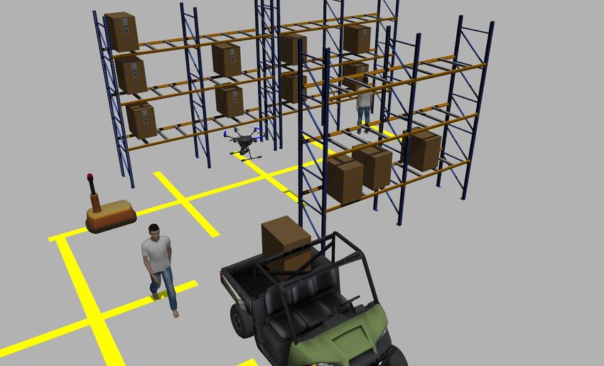
presence of GPS signal is generally weak or unavailable for Fig. 1: Cropped view of a typical large scale warehouse
the drones to localize in a global frame. This type of scenario environment automated with the help of ground robots; The
is commonly found in industrial and warehouse environments presented approach suggests the use of existing guidelines
that more or less functions in the indoor conditions. Figure for the deployment of inspection drones
1 shows a scenario from a large warehouse system updating
towards its automation. A navigation stack will only make sense if the drone is
For any mobile robot working in an application, the capable of localizing in an environment. For the presented
primary task it must be excelling at is navigation. There case, we need to localize using the lines and nodes exist-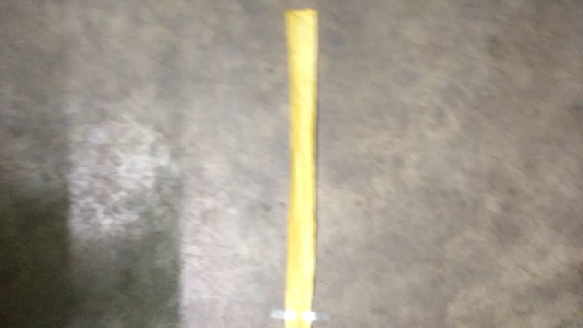
II. RELATED WORK

                                                                    Large warehouses across the country lose millions of
                                                                 dollar every year due to lost inventory. Manual scanning of
                                                                 inventory is both time-consuming and prone to error. This
                                                                 problem of real-time warehouse inspection system has been
                                                                 approached by different entities. Kiva Systems, now owned
                                                                 by Amazon, has implemented an autonomous inventory
                                                                 system in their warehouses that track both the location and
                                                                 contents of every bin in the warehouse using AGVs. Few of
Fig. 2: Overview of the proposed workflow for warehouse
                                                                 the problems that this system face include a limited height of
inventory management by the drone
                                                                 the shelf, a requirement of a manual process for the inventory
                                                                 scanning and low-speed manoeuvre of the ground vehicles.
                                                                 Another option available in the industry involves deploying
ing in the environment for which we need to detect the           an infrastructure of permanent shelves with built-in RFID
thick guidelines first. One of the most widely used line         readers such that the shelf can recognize the item being
detection algorithms is Hough-line-based detection, but it       stored in it. While this system gives a real-time scan of
has many limitations that are expected to create problems        the inventory, the permanent shelf doesn’t allow the ground
in a real-world scenario. Much of the efficiency of the          robots to automate the inventory movement.
Hough transform [1] relies upon the quality of input data
                                                                    MIT’s RFly [2] used relays which during the flight picked
i.e., the edges have to be detected well for the Hough
                                                                 RFID responses from various sites along the path of the
transform to be efficient. Using the vanilla hough transform
                                                                 drone, and handled these spatial measurements as an antenna
on the noisy images is considerably prone to the haywire
                                                                 array. Later, by applying the antenna array equations to these
detections, and generally, to tackle this, a denoising stage
                                                                 measurements, they can localized RFIDs. This method is
is prefixed. A rule-based denoising framework leads to the
                                                                 based on previous work on Synthetic Aperture Radar (SAR)
occurrence of variance by threshold configurations, whereas,
                                                                 systems. Another organization, Infinium Robotics, used a
a learning-based denoising framework leads to an increase in
                                                                 miniature ground vehicle mounted with a visual tag for the
computational load. Hence, we propose a pipeline for robust
                                                                 drone to follow between the shelf gaps. This type of method
line detection that overcomes these problems by reducing the
                                                                 increases the cost per drone because of the requirement of
artifacts to a state easily detected by hough line algorithm
                                                                 an additional ground robot to act as a guide.
with less severe errors.
                                                                    For all such drones developed towards warehouse automa-
   A standard thick line detection algorithm generally sup-
                                                                 tion, localization stands as the most critical module. Hence,
ports the following steps:
                                                                 we considered it important to review the present state of lo-
  1)   Denoising                                                 calization methods for structured environments. The current
  2)   Line Segmentation / Thresholding                          state-of-the-art algorithms in this direction are majorly the
  3)   Edge Detection                                            existing algorithms in simultaneous localization and mapping
  4)   Hough Line Transform                                      (SLAM) for autonomous robots using different sensor setups.
  5)   Combining multiple results                                For example, LSD-SLAM [3] and ORB-SLAM2 [4] used
   The pipeline we propose in this paper, as shown in Figure     stereo camera, DSO [5] and VINS-Mono [6] used monocular
2, starts with subscribing to the down-facing camera images      camera with inertial sensor, the work presented by Hess et.
from the drone platform. A thick-line detection algorithm        al. [7] and Bosse et. al. [8] used LiDARs, etc. Although these
was implemented as a part of machine vision which holds          methods work quite well even in unstructured environments,
significant value for the optimal performance of localization.   sensors like stereo camera and LiDAR systems are, in
The paper is divided into following sections. Literature         general, bulky to be used on-board UAVs in a constrained
review and relevant studies in this direction are discussed in   environment with a considerable cost of deployment for
Section II. Sections III states all the assumptions and con-     large-scale application. Moreover, these systems have high
ventions considered while the development of the framework.      computational power and memory need that renders them
Section IV gives a walk-through of different methods applied     unsuitable for on-board use of a micro-aerial vehicle (MAV).
with a brief discussion. Section V describes the control and     Our method, therefore, utilizes the presence of structured
localization implementation for the drone using the output       environment, like the use of grid lines available in typical
from our thick-line detection algorithm. Any offset of drone     warehouses for the movement of ground robots, to build a
from the closest safe point of hovering (i.e. intersection of    robust and computationally efficient solution that allows the
two guidelines) is reduced with multiple PID loops acting        drone to localize itself on a warehouse map with a sufficient
on the lines detected within the image. Thus, discretizing       accuracy. A previous grid-based localization system [9] used
the drone’s location to nodes co-ordinates. Finally, section     the properties of particularly structured grid-lines to localize
VI discusses a navigation strategy that we suggest for the       a MAV inside each sub-cell of the grid. However, it required
drone to follow in the given structured environment.             a minimum of three vertical and horizontal equally spaced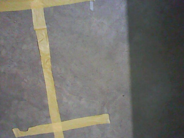
grid lines for sufficiently accurate localization. Our method    some acceptable conditions have been assumed. The lines
removes this extra constraint of having multiple lines by        and nodes are assumed to be next to the cargo shelf where
employing a combination of elegant and simpler strategies        drone needs to stop and scan for the QR codes and report
with discrete localization on nodes.                             the location corresponding to the nodes. A typical warehouse
                                                                 setup following the stated assumptions is shown in Figure 4.
     III. ASSUMPTIONS AND CONVENTIONS                            The horizontal line should end before some distance (DY )
A. Conventions                                                   from the shelf to avoid any contact of the drone with the
  The following conventions are used in this paper:              boxes. DY , DX (distance between any two adjacent nodes)
                                                                 and σ can be related by a simple equation given by
  1) The drone’s coordinate system: X-axis and Y-axis are
     along the roll and pitch axis of the drone in hovering                                               σ
                                                                                   DX = 2 × DY × tan( )                    (1)
     mode respectively, the origin being the centre of the                                                2
     drone.                                                      where
  2) Vertical line: The straight line parallel to the shelf.             σ ← Field of view of the mounted camera. Equation
  3) Horizontal line: The straight lines perpendicular to the    (1) can be easily realized from Figure 2.
     shelf.                                                         The vertical length between the start of any shelf and the
  4) θ : Angle made by the perpendicular to the vertical         first node must be less than or equal to D2x .
     line from origin with the X-axis in drone’s co-ordinate
     system
  5) ρ : The length of the perpendicular to the vertical line
     from origin with the X-axis in drone’s Co-ordinate
     system. Figure 3 shows a sample snapshot containing
     drone with its co-ordinate axes, the vertical line, the
     parameters rho and theta.
  6) The pitch angle of the drone is along the horizontal
     line and roll angle along the vertical line.
  7) -10° ≤ roll ≤ 10°, though we only used to give roll
     in range of -1° and 1°.
  8) -10° ≤ pitch ≤ 10°, though we only used to give pitch
     in range of -1° and 1°.
  9) -10° ≤ yaw-rate ≤ 10°, though we only used to give
     yaw-rate in range of -1° and 1°.
                                                                              Fig. 4: A typical Warehouse setup

                                                                    For a controlled environment like a warehouse, constant
                                                                 pressure with negligible wind is assumed to minimize the
                                                                 errors in height estimation using a barometer, good light-
                                                                 ing condition is expected for crisp grid detection and QR
                                                                 code detection. Any moving obstacle like forklifts, overhead
                                                                 chains, etc which can hinder the path of the drone is assumed
                                                                 to be absent or away from the drone’s route.
                                                                                   IV. VISION SYSTEM
                                                                    For the presented work, vision algorithms hold a crucial
                                                                 position for the drone navigation as it allows the drone to
                                                                 localize within the grid structure. In such a scenario, using a
                                                                 simple method consisting of canny and hough transform as
                                                                 line detection method might seem promising, but is equally
Fig. 3: rho (ρ) and theta (θ) convention with respect to         risky to use citing its naivety under extreme conditions.
drone’s local co-ordinate axis                                   Hence, it is necessary to improve certain sections of the
                                                                 grid detection algorithm focusing towards robustness while
                                                                 also keeping the time complexity similar to the simple
B. Assumptions
                                                                 method as above. Following sub-sections discuss some of
   A warehouse is a well-structured environment. The boxes       the improvements, we propose.
or cargo placed in a warehouse shelf may have different sizes
i.e., there may not be a specific constant horizontal distance   A. Line Thresholding
between any two adjacent boxes. To take such situations            Image input is converted to HSV colour space for thresh-
into account and to ensure that no box is left unscanned,        olding as it provides a better thresholding accuracy compared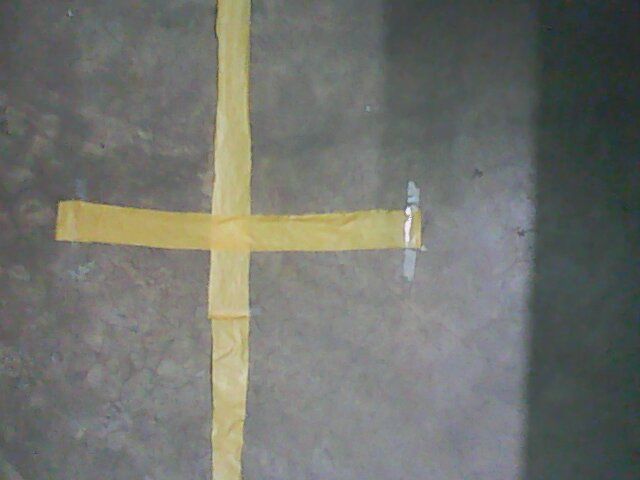
to RGB colour space. A Support Vector Machine model Algorithm 1 Centroid Extraction
[10] was used to train the thresholding of different colour 1: procedure C ENTROID(image, Nheight , Nwidth )
segments and used region growing algorithm on top of it to 2: images ← divide(image, Nheight , Nwidth )
identify the line bands for varying brightness and intensities. 3: for img in images do
We trained our model to detect yellow colour under varying 4: contours ← contour(img)
conditions and lighting. Results were tested on blurred and 5: contourM ax ← M axarea (contour)
distorted video and our model was robust enough to quickly 6: M ← moment(contourM ax )
threshold the line with minimal loss in accuracy. Figure 5 7: CentreX = M10 /M00
shows the effectiveness of colour segmentation using the 8: CentreY = M01 /M00
above method. 9: push CentreX , CentreY
10: image ← concatenate(images)
11: return image
(a) Input Camera Feed (b) Thresholded Line
Fig. 5: Line Thresholding in HSV Space using SVM
(a) Thresholded Line (b) Centroid separation
B. Line Tracking
1) Centroid Method: The thresholded image was broken
into W × H slices which are dynamically identified based
on the lines coverage area in the image, e.g., increasing the
altitude of drone reduces the thickness of line thus greater (c) Centroid of sub-parts
slices are needed to detect the line features properly. For Fig. 6: Centroid Detection
a very large area of lines in the image, the slices can be
reduced, while for a small area of lines more slices are
needed to cover all the curves and turn in the lines. Each 2) Skeletonization: The centroid method can get computa-
slice was processed in parallel to find the centroid of each tionally expensive for an on-board processor fitted on drones
slice using OpenCV and contour detection. Moments of each like Raspberry Pi; an alternative method can be used to attain
contour was calculated and the centroid was returned for each respectable performance compared to the centroid method.
slice of the image. Figure 6 shows the centroid extraction The morphological skeleton of a shape is a thin version of
result on a sample image. the form that is formed at the centre of the shape, equidistant
Moment of any object in 2D space is given by from the edges. It usually emphasizes the geometric and
Z ∞Z ∞ topological features of the structure, such as shape, topology,
Mpq = xp y q f (x, y)dxdy (2) length, direction, and width.
−∞ −∞
The thresholded image was converted to binary and im-
For a grayscale image with pixel intensity I(x,y) , raw age was eroded to obtain the skeleton view of the image.
moment is given by Thinning algorithm by Zhang-Suen [12] was used to thin
XX the contours to a few pixels wide producing a single straight
Mij = xi y j I(x, y) (3) line for the hough line to work properly. Hough transform
x y was then used to find the lines from the reduced skeletonized
points. Figure 7 shows one such sample of application of
Centroid of the object then can be calculated as this method with comparison with canny edge detection. To
further reduce the error, mean clustering was used to cluster
M10
x̄ = (4) lines to an accuracy of 5 degrees. Two ranges of θ were
M00
considered for classifying as a vertical or horizontal line.
M01
ȳ = (5)
M00 vertical, if 0° ≤ θ < 30°
Line = vertical, if 150° < θ < 180° (6)
Image slices were then concatenated to form an image with
horizontal, otherwise
the centroid points. These centroid points were used for
RANSAC [11] model fitting to find the best fitting line for Lines are sorted into vertical and horizontal topics using
the given set of points. means clustering with a specific threshold and are clustered
nodes after applying this method to a sample image. This
                                                                  helps to provide yaw feedback to the drone with respect to
                                                                  the line and can correct any other orientation errors induced
                                                                  in the system.

       (a) Input Camera Feed       (b) Canny Edge Detection

                                                                  (a) Input image with 2 (b) Averaging effect (c) Clustering rho, theta
                                                                  nodes

                                                                  Fig. 9: Effectiveness of the clustering algorithm on multiple
                                                                  line detections for identifying the next target or the closest
                                                                  node
       (c) Skeleton Extraction             (d) Ours

Fig. 7: Line detection comparison between the use of                 A closed-loop PID controller was used on the roll, pitch
skeleton extraction and canny edge detection before the           and yaw rate of the drone with the lines pose as feedback
application of hough line transform                               to control the x and y position, and yaw of the drone with
                                                                  respect to the grid lines. The design of PID controller that
                                                                  was implemented for our purpose is shown in Figure 10. The
                                                                  velocity output of each of the control loop was clipped to a
                                                                  range [−0.1, 0.1] to avoid the possibility of drone deviating
                                                                  by unexpectedly high value and the grid line getting out of
                                                                  the field-of-view of the down-facing camera. PID equation
                                                                  of each subsystem is given as follows:
                                                                                                  Z
                                                                                                                 de(t)
                                                                            P ID = KP e(t) + KI e(t) + KD                   (7)
                                                                                                                  dt
                                                                     where:
           Fig. 8: Clustering of Lines based on θ                         KP : Proportional Constant
                                                                          KI : Integral Constant
                                                                          KD : Derivative Constant
into a group of two lines. Figure 8 shows the threshold range             w: Image Width
and permitted perturbation for the line clustering.                       h: Image Height
   If the skeletonization method is used for line detection,              ∆x = w2 - ρvertical
there may be an offset in the line detected because of the                ∆y = h2 - ρhorizontal
nature of skeletonization algorithm. This can be tackled by               ∆θ = 0 - θhorizontal
fusing the data from centroid as well as skeletonization, if              integral = integralprevious + error
the hardware permits, to gain more accurate line detections.              derr = error - errorprevious
          V. CONTROL AND LOCALISATION                                     dt : execution time
                                                                     Even though the roll and pitch angles were clipped to
   The centroid or skeletonization algorithm returns a set        a small value, the instantaneous orientation of the drone
of lines that sometimes are found to be fluctuating by a          created an offset in the position of the line in an image
small quantity, which then affects the stability of the drone     as shown in Figure 11. This offset was observed to be
while following the line. Therefore, a simple Kalman filter       proportional to the altitude (H) and tangent (trigonometric
was applied on the output line equations (parameters in the       function) of the roll or pitch angle of the drone for vertical
Hessian form) to minimize the effect of jitters and random        line and horizontal line respectively. To compensate for this
false lines produced by the cluttered noise in the image.         offset for accurate estimation of the position of lines, we
   A clustering algorithm was also implemented in case of         implemented an offset correction step before sending the
skeletonization which further normalizes any erroneous data       line error signal to the controller. The correction step is
produced due to the branching of the skeleton of the line i.e.,   formulated as follow:
multiple perpendicular lines to the reference line occurring
in an image. Assuming resolution of the line to be in the                    ρCorrected = ρvertical − H × tan(roll)                 (8)
                                                                              vertical
range of 5°, lines were clustered in different pairs with 5°
difference between them. Figure 9 shows the detection of two              ρCorrected
                                                                           horizontal   = ρhorizontal − H × tan(pitch)              (9)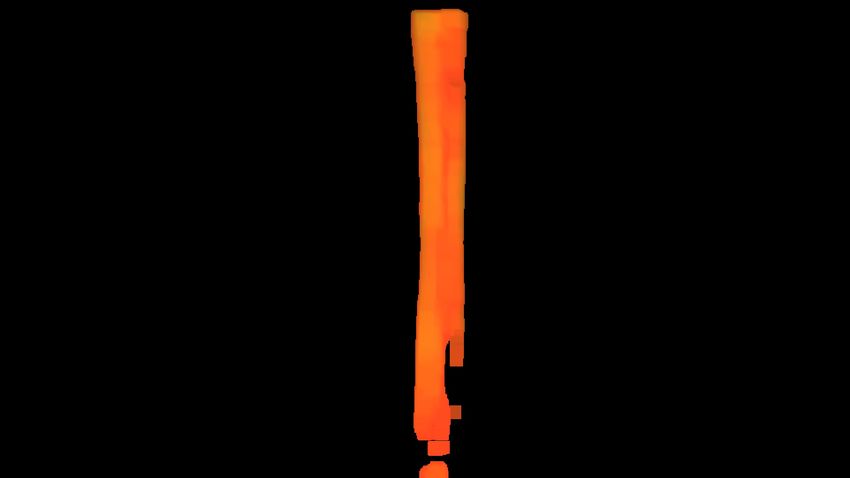
drone for its functioning can be modified. For example, if the
                                                                grid structure is available, grid nodes are used as intermediate
                                                                targets. In our implementation, these intermediate targets
                                                                were identified and tracked by the strategy module depending
                                                                upon the global target or task to be accomplished, like
                                                                detection and localization of the goods using the bar-codes
                                                                and QR codes.

                                                                A. Turn detection
                                                                   Apart from nodes and vertical lines, curved or sharp turns
                                                                can also be present in the environment which can be mistaken
                                                                as a node if not dealt with properly by the algorithm. To avoid
                                                                such a situation, an L-detection algorithm was implemented
                                                                which differentiated an L from a regular node. The ratio
                                                                of the number of pixels on the left to right side of the
                                                                skeletonized line was considered, and a threshold ratio was
                                                                set which, when exceeded, referred to a turn in the path.

                                                                B. Multiple Line Handling
                                                                   The case of multiple nodes being detected in a given
                                                                position is handled by tracking the goal node. Once the
                                                                lines and their ρ and θ values are detected, lines are divided
                                                                into two different topics, vertical and horizontal. Vertical line
                                                                published is used for the traversal of the drone. An imaginary
Fig. 10: Block diagram of our implemented control system.       horizontal line is assumed in front of the horizontal lines
                                                                which helps the drone steer forwards. Multiple horizontal
                                                                lines may cause problems when the height is changing as
   Finally, the PID control loops were tuned independently      ρ and θ value of each line might change significantly thus
one by one first and then together using the previously         drone’s returning to the same line becomes a difficult task.
estimated parameters as the starting point. Figure 14 shows     To tackle the problem, we have a constantly updating line
the experimental setup along with the drone used for tuning     coordinate which keeps track of current drone hover line
the parameters.                                                 parameters and updates the specific lines at different heights
                                                                so that the drone doesn’t lose the tracking in case multiple
                                                                horizontal lines are visible. The strategy commands the
                                                                controller to hover the drone over a specific goal node. We
                                                                also included some exceptional cases that are bound to occur,
                                                                e.g., the starting point/take-off strategy and endpoint/charge
                                                                station detection for actual deployment scenario.
(a) 0% of maximum roll.(b) 50% of maximum(c) 90% of maximum      VII. EXPERIMENTAL SETUP AND EVALUATION
                       roll.             roll.
                                                                   All the demonstrated methods and strategies were imple-
Fig. 11: Offsets in the position of line with increasing roll   mented on a Parrot AR Drone 2 with variants like off-board
angles                                                          processing on remote compute unit and on-board processing
                                                                with Raspberry Pi 3. The remote compute unit was equipped
                                                                with Intel Core i7 7th Gen @2.7GHz x 4 processor with 32
                     VI. STRATEGY                               GB on-board RAM. For the other variant, Raspberry Pi 3
   While it is important to understand the environment and      was attached to the bottom of AR Drone which led to a
localize oneself, it is of equal importance to formulate a      decrease in flight time as it drew power from the drone’s
strategy for accomplishing the set goal. Our navigation stack   battery and also added up to the drone’s weight. This was
helps the drone to comply with this simple notion. Like         compensated using a Lithium-ion battery that provided more
any other robotic decision-making process, we defined the       charge density than the standard one. We implemented our
following key modules on which our system works.                pipeline on these variants and evaluated the performance.
      a. Perception                                             Before the actual hardware deployment, all the necessary
      b. Control and Localization                               tests were made on a Gazebo simulation as shown in Figure
      c. Strategy                                               13. AR drone hosts two cameras, from which we targeted
   Sections IV and V appertain to the first two modules.        the down-facing camera for localization and the front-facing
Depending on the environment, the strategy employed by the      camera for detecting QR-Code/Barcode. We chose Robot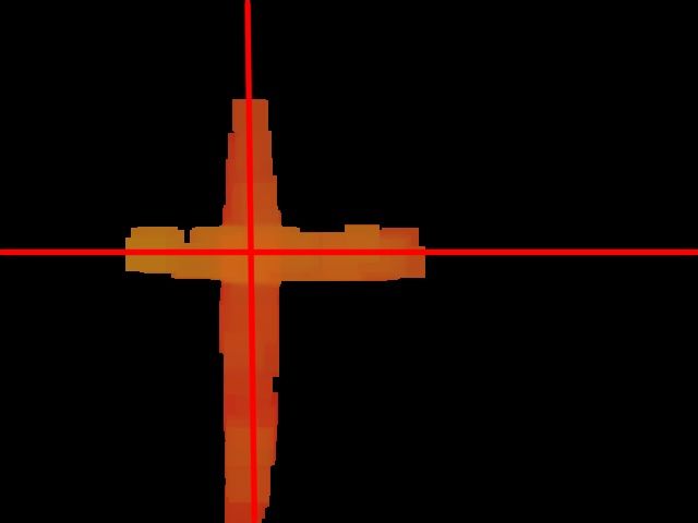
a.

 b.

 c.

 d.

 e.

Fig. 12: From Top to Bottom: a. Test Cases of the warehouse strip; b. Line detection using naive hough line, canny and
manual thresholding; c. Skeleton generation using the thinning algorithm; d. Output from centroid method; e. Merged final
output from skeletonization and centroid approach.

Operating System (ROS) for retrieving drone’s on-board             axis). We measured the performance of different methods by
sensors data and also for sending appropriate command              calculating the absolute errors in r and α of the generated
actions to it. ROS package ardrone autonomy was used for           line with respect to the ground truth line. We collected about
this purpose. Image processing on drone-sent camera data           50 images containing different views of the grid structure
was done with the help of the OpenCV library. Finally, all the     both from the simulation world and real world experimental
data handling and processing codes were written in optimized       setup each. The ground truth for each of these images was
multi-thread C++ code to match the industrial standards.           drawn manually as perceived by the human mindset and
Table I shows On-board (fps) Vs Off-board (fps) for Centroid       was later converted into hessian normal form. Some of
and Skeletonization Methods.                                       the images and the result of the application of discussed
                                                                   methods in the previous sections are shown in Figure 12.
A. Evaluation Metric and Results                                   Table II shows the performance of methods on an average
   Better performance of the grid-localization relates to better   over 50 images. Results show Naive approach suffer due to
grid-line detection by the machine vision algorithm. Hence,        thick lines. This causes it to create multiple lines and thus
we provide an evaluation, particularly for the line detection      reducing the accuracy of the approach. Moreover, multiple
algorithms. Any line in a plane can be represented by              horizontal lines are averaged out as one due to clustering
Hessian normal form of the equation of line in parameters          which further causes error, especially in real test cases.
r (normal distance of the line from the origin) and α (angle       Centroid approach works by dividing the line into smaller
made by the normal vector to the line with one of the
parts and taking average over it which reduces the errors multiple lines effectively gives the closest node to which the
significantly and provides very accurate ρ and θ values. intermediate target should be set to. At any point in time, the
Skeletonization, on other hand, works by reducing the lines offset from this set-position is reduced iteratively by multiple
to single pixel thickness. This induces errors in θ of the final PID loops. This simple yet effective localization method
line but comparatively fewer errors in ρ compared to centroid gives a competitive performance regarding speed as com-
approach. Combined approach sees a balanced accuracy of pared to the application of heavy SLAM algorithms on same
both the approaches separately as it normalizes some of the computing power. Though we cannot expect comparable
drawbacks from each approach. accuracy as we discretized the locations of the drone to nodes
co-ordinates, the algorithms achieve decent accuracy in terms
of node coordinates as the application area doesn’t require
per position localization in a well-defined environment. The
proposed navigation strategy makes the drone capable of
planning a sub-optimal route to attain global target/setpoint.
We finally end our conclusion with the restatement that
monocular camera-based vision techniques when designed
Fig. 13: Simulation environment developed for verifying appropriately can perform significantly well as compared to
complete navigation stack price one needs to pay for using full SLAM-based solutions.
ACKNOWLEDGMENT
We would like to thank the institute authorities at Indian
Institute of Technology Kharagpur (session 2017-18) and IIT
Gymkhana body to avail us the funds as a support for the
presented work. Also, a special thanks to members of Aerial
Robotics Kharagpur group for providing us their working
space and insights time to time for the betterment of the
project.
R EFERENCES
Fig. 14: Experimental setup for AR drone’s PID tuning on [1] P. Hough, “Method and means for recognizing complex patterns,” Dec
grid lines using roll, pitch and yaw as control variables 1962.
[2] Y. Ma, N. Selby, and F. Adib, “Drone relays for battery-free networks,”
in Proceedings of the Conference of the ACM Special Interest Group
on Data Communication. ACM, 2017, pp. 335–347.
[3] J. Engel, J. Stückler, and D. Cremers, “Large-scale direct slam with
TABLE I: Performance evaluation of our method on different stereo cameras,” in Intelligent Robots and Systems (IROS), 2015
hardware. IEEE/RSJ International Conference on. IEEE, 2015, pp. 1935–1942.
[4] R. Mur-Artal and J. D. Tardós, “Orb-slam2: An open-source slam
Method On-board (fps) Off-board (fps) system for monocular, stereo, and rgb-d cameras,” IEEE Transactions
Centroid 4.23 15.10 on Robotics, vol. 33, no. 5, pp. 1255–1262, 2017.
Skeletonization 8.93 20.0 [5] J. Engel, V. Koltun, and D. Cremers, “Direct sparse odometry,” IEEE
transactions on pattern analysis and machine intelligence, vol. 4,
2017.
[6] T. Qin, P. Li, and S. Shen, “Vins-mono: A robust and versatile monoc-
ular visual-inertial state estimator,” arXiv preprint arXiv:1708.03852,
TABLE II: Performance evaluation of different method on a 2017.
dataset of images of size 1920×1080. [7] W. Hess, D. Kohler, H. Rapp, and D. Andor, “Real-time loop closure
in 2d lidar slam,” in Robotics and Automation (ICRA), 2016 IEEE
International Conference on. IEEE, 2016, pp. 1271–1278.
Simulation Real-world [8] M. Bosse and R. Zlot, “Continuous 3d scan-matching with a spinning
Method
∆r (px) ∆α (°) ∆r (px) ∆α (°) 2d laser,” in Robotics and Automation, 2009. ICRA’09. IEEE Interna-
Naive approach 56 3 78 12 tional Conference on. IEEE, 2009, pp. 4312–4319.
Centroid 10 3 18 5 [9] M. P. Das, G. Gardi, and J. Mukhopadhyay, “5-dof monocular visual
Skeletonization 5 4 15 10 localization over grid based floor,” in Indoor Positioning and Indoor
Combined 6 3 16 7 Navigation (IPIN), 2017 International Conference on. IEEE, 2017,
pp. 1–7.
[10] X.-Y. Wang, T. Wang, and J. Bu, “Color image segmentation using
pixel wise support vector machine classification,” Pattern Recognition,
VIII. CONCLUSIONS vol. 44, no. 4, pp. 777–787, 2011.
[11] M. A. Fischler and R. C. Bolles, “Random sample consensus: a
The proposed pipeline demonstrates promising result in paradigm for model fitting with applications to image analysis and
automated cartography,” Communications of the ACM, vol. 24, no. 6,
both simulation world and real world scenario. Both of our pp. 381–395, 1981.
line detection algorithms get away the limitations of pure [12] T. Zhang and C. Y. Suen, “A fast parallel algorithm for thinning digital
hough line transform. Depending upon the hardware avail- patterns,” Communications of the ACM, vol. 27, no. 3, pp. 236–239,
1984.
able, we show the capability of the method to outperform
classical techniques. Our clustering algorithm on rho, theta ofYou can also read