GV-Backup Center User's Manual V1.2.1 - Amazon S3
←
→
Page content transcription
If your browser does not render page correctly, please read the page content below
GV-Backup Center
     User's Manual V1.2.1

                     BCV121-UM-A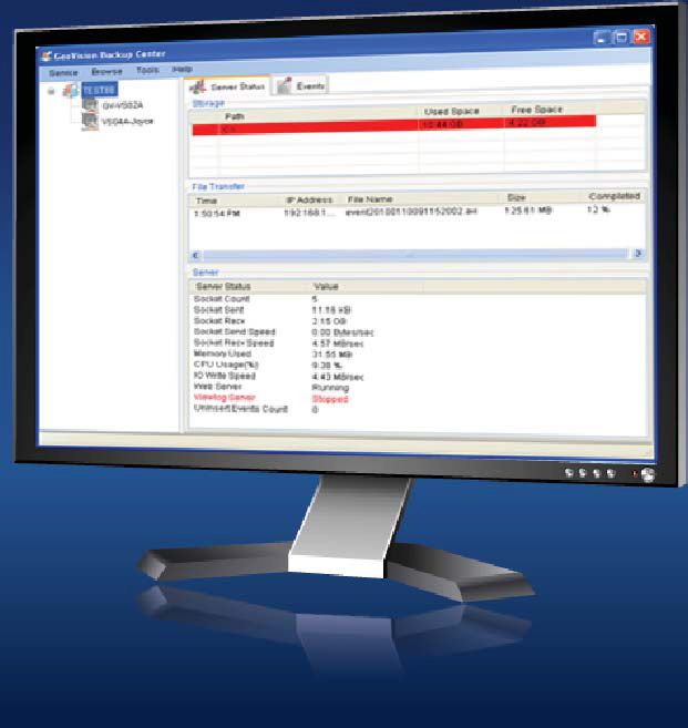
© 2021 GeoVision, Inc. All rights reserved.
Under the copyright laws, this manual may not be copied, in whole or in part,
without the written consent of GeoVision.

Every effort has been made to ensure that the information in this manual is
accurate. GeoVision, Inc. makes no expressed or implied warranty of any kind
and assumes no responsibility for errors or omissions. No liability is assumed
for incidental or consequential damages arising from the use of the information
or products contained herein. Features and specifications are subject to
change without notice.

GeoVision, Inc.
9F, No. 246, Sec. 1, Neihu Rd.,
Neihu District, Taipei, Taiwan
Tel: +886-2-8797-8377
Fax: +886-2-8797-8335
http://www.geovision.com.tw

Trademarks used in this manual: GeoVision, the GeoVision logo and GV
series products are trademarks of GeoVision, Inc. Windows is the registered
trademark of Microsoft Corporation.

October 2021

Scan the following QR codes for product warranty and technical support
policy:

      [Warranty]            [Technical Support Policy]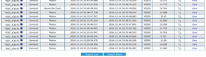
Contents
Naming and Definition ......................................................................... iii
Chapter 1 Introduction......................................................................... 1
    1.1 Features .................................................................................................................. 2
    1.2 Compatible GeoVision Software and IP Devices ..................................................... 3
    1.3 System Requirements ............................................................................................. 4
    1.4 Network and HDD Requirements for GV-DVR / NVR, GV-VMS, and GV-IP Devices5
    1.5 Requirements for Connecting to GV-Recording Server ........................................... 7
    1.6 Requirements for Connecting to GV-VMS ..............................................................10
    1.7 Data Transfer Time between Different Network Types ...........................................11

Chapter 2 Installation......................................................................... 12
Chapter 3 Getting Started.................................................................. 13
    3.1 Starting the GV-Backup Center ..............................................................................13
    3.2 Connecting GV-IP Devices .....................................................................................14
           3.2.1 Setting Backup Frequency ..........................................................................16
    3.3 Connecting GV-DVR / NVR ....................................................................................17
    3.4 Connecting GV-VMS ..............................................................................................21
    3.5 Connecting GV-Recording Server ..........................................................................24
    3.7 Assigning Backup Locations...................................................................................27
    3.8 Setting E-Mail Notifications.....................................................................................29
           3.8.1 Setting Mail Server......................................................................................29
           3.8.2 Setting E-Mail Alerts....................................................................................30
Chapter 4 Configuring the GV-Backup Center................................. 32
    4.1 General Settings.....................................................................................................32
    4.2 Account Settings ....................................................................................................33
    4.3 Storage Settings.....................................................................................................34
    4.4 Database Settings ..................................................................................................36
    4.5 E-Mail Settings .......................................................................................................36
    4.6 File Transfer Settings .............................................................................................37

Chapter 5 Accessing the Backup Data Using a Web Browser........ 40
    5.1 Accessing the Web Interface ..................................................................................40
    5.2 Tree Menu..............................................................................................................42

                                                                i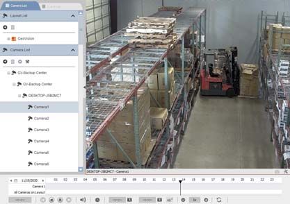
5.3 System Event List Query ........................................................................................43
     5.4 Login and Logout Query .........................................................................................44
     5.5 Monitor Event List Query ........................................................................................45
     5.6 Analysis by Event Count.........................................................................................46
     5.7 Analysis by Event File Size.....................................................................................47
     5.8 Analysis by Time ....................................................................................................48
     5.9 Analysis of File Size by Time..................................................................................49

Chapter 6 Remote Playback .............................................................. 50
     6.1 Connecting through Remote ViewLog Program......................................................50
            6.1.1 Remote ViewLog V1....................................................................................50
            6.1.2 Remote ViewLog V2....................................................................................51
Chapter 7 Media Man Tools............................................................... 52
     7.1 The Media Man Tools Window ...............................................................................52
     7.2 Adding a Disk Drive ................................................................................................53
     7.3 Removing a Disk Drive ...........................................................................................53
     7.4 Setting LED Panel ..................................................................................................54

Specifications...................................................................................... 56
Appendix ............................................................................................. 57
     A. Modifying Port Number for running GV-Backup Center on the same computer with
     GV-DVR / NVR and GV-VMS ........................................................................................57
     B. Installing .Net Framework 3.5 for Windows 10 / Server 2016 ...................................58
     C. How to Repair the Database ....................................................................................61

                                                              ii
Naming and Definition
GV-DVR / NVR   Analog and Digital Video Recording Software. The GV-DVR / NVR
               also refers to Multicam System, GV-NVR System, GV-Hybrid DVR
               System and GV-DVR System at the same time.
GV-VMS         GeoVision Video Management System for IP cameras.
GV-Recording   GeoVision video streaming server designed for large-scale video
Server         surveillance deployments. It supports recording from IP devices and
               can distribute channels to GV-DVR / NVR, GV-GIS, GV-Mobile
               Server, GV-Control Center and GV-Multi View.
GV-Remote      GeoVision viewing software that allows you to play back recorded
ViewLog        Files remotely.

                                      iii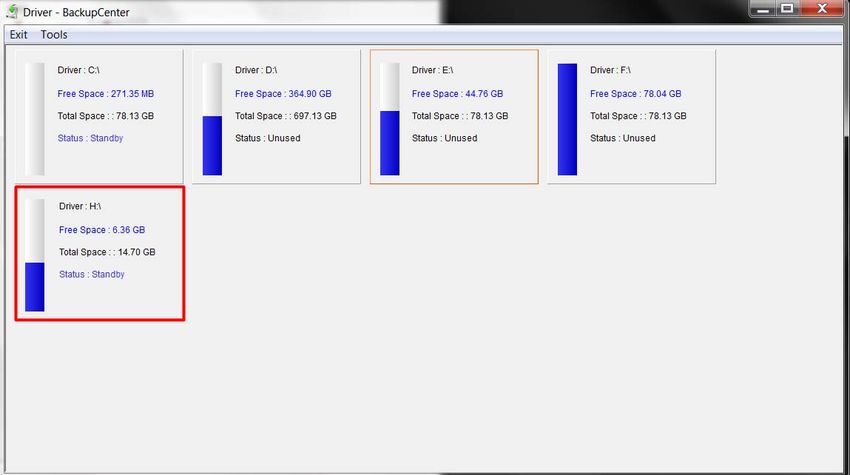
1 Introduction
Chapter 1 Introduction
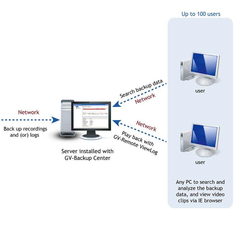
GV-Backup Center provides you with a secure and affordable remote backup solution for
GV-DVR / NVR, GV-VMS, GV-Recording Server and GV-IP Devices. GV-Backup Center
automatically stores a copy of recordings and logs to an offsite location. If data are lost at
where GV-DVR / NVR, GV-VMS, GV-Recording Server or GV-IP Devices are located, the
recording data remain safe in a different location.
1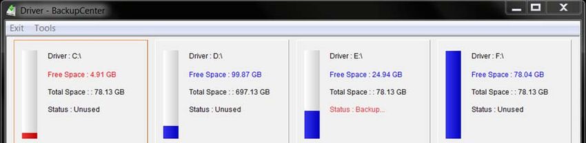
1.1 Features
Remote backup
Up to 200 units of GV-IP Devices supported
Up to 12 units of GV-DVR / NVR supported (32 ch per unit)
Up to 6 units of GV-VMS supported (64 ch per unit)
Up to 3 units of GV-Recording Server supported (128 ch per unit)
Up to 10 backup rules for working and non-working days independently for GV-DVR /
NVR, GV-VMS and GV-IP Devices
E-Mail alerts for low disk space, disconnection and file transfer failure
Online data analysis by Event Counts, File Size and Time
Failover support
2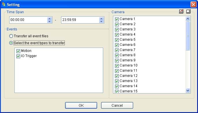
1     Introduction

1.2 Compatible GeoVision Software and IP Devices
Compatible GeoVision Software
Product                                                Software Version
GV-DVR / NVR                                           8.5.5 or later
GV-Recording Server                                    1.2.4 or later
GV-VMS                                                 16.10.3 or later

Non-Compatible IP Devices
Except the following non-compatible IP Devices, the above mentioned GeoVision software,
GeoVision IP cameras, Video Servers and Compact DVR all support GV-Backup Center.
Product
GV-Box IP Camera                      GV-BX2600
                                      GV-EFD1100 Series
                                      GV-EFD2100 Series
                                      GV-EFD4700 Series
GV-Target Mini Fixed Dome
                                      GV-EFD2101
                                      GV-EFD3101
                                      GV-EFD5101
                                      GV-EDR1100 Series
GV-Target Mini Fixed Rugged Dome      GV-EDR2100 Series
                                      GV-EDR4700 Series
GV-Mini Fixed Rugged Dome             GV-ADR Series / GV-TDR Series
                                      GV-EBX1100 Series
GV-Target Box Camera
                                      GV-EBX2100 Series
GV-Eyeball Dome                       GV-EBD Series
                                      GV-EVD2100
GV-Target Vandal Proof IP Dome        GV-EVD3100
                                      GV-EVD5100
                                      GV-AVD Series / GV-TVD Series
GV-Vandal Proof IP Dome
                                      GV-VD8700
                                      GV-EBL2101
GV-Target Bullet Camera               GV-EBL2111
                                      GV-EBL3101
GV-Bullet IP Camera                   GV-ABL Series / GV-TBL Series
                                      GV-SD2322-IR
                                      GV-SD2722-IR
GV-Speed IP Dome
                                      GV-SD3732-IR
                                      GV-SD200-S
GV-Thermal IP Camera                  GV-TM0100
GV-Virtual Reality IP Camera          GV-VR360

                                            3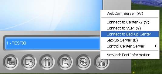
1.3 System Requirements
The following is minimum system requirements for the server to run the GV-Backup Center.

Minimum System Requirements
 OS              64-bit Windows 10 / Server 2016
 CPU             Core 2 Duo, E6600, 2.4 GHz
 Memory          2 x 2 GB Dual Channels
 Hard Disk       1 GB
 DirectX         9.0c
 Software        .Net Framework 3.5
 Browser         Internet Explorer 7.x
 Hardware        External or Internal GV-USB Dongle
 Note: To download .Net Framework, see Chapter 2 Installation.

Note: Considering of connection speed, we do not recommend using the mobile broadband
connection, such as HSDPA, UMTS, EDGE, GPRS, GSM and etc., between GV-IP
Devices and GV-Backup Center.

                                            4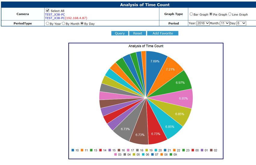
1    Introduction

1.4 Network and HDD Requirements for GV-DVR / NVR,

GV-VMS, and GV-IP Devices
The server’s backup speed and transmitting capacity vary depending on the number of
Gigabit connections. The number of Gigabit network cards required to receive 200 GV-IP
Devices and to support remote access of backed up data are listed below according to the
resolution of the source video.

Also note the maximum number of hosts supported by a single hard disk to calculate the
number of hard disks required.

                                           Gigabit Network Cards Required
                                                                                          Max. hosts
Resolution     FPS     Codec
                                    Receiving 200 GV-IP           For Playback /           per HDD
                                         Devices                 Web Query access

                                  Gigabit network card x 2
  1.3 MP      30 fps    H.264                                  Gigabit Network Card x 1    32 hosts
                                  (up to 100 hosts per card)

                                  Gigabit Network Card x 3
  2.0 MP      30 fps    H.264                                  Gigabit Network Card x 1    21 hosts
                                  (up to 67 hosts per card)

                                  Gigabit network card x 2
  3.0 MP      20 fps    H.264                                  Gigabit Network Card x 1    32 hosts
                                  (up to 100 hosts per card)

                                  Gigabit Network Card x 3
  4.0 MP      15 fps    H.264                                  Gigabit Network Card x 1    24 hosts
                                  (up to 67 hosts per card)

                                  Gigabit Network Card x 3
  5.0 MP      10 fps    H.264                                  Gigabit Network Card x 1    24 hosts
                                  (up to 67 hosts per card)

                                               5
The deployment of Gigabit connections for backing up and accessing database is suggested
as illustrated below. Ensure to run every Gigabit connection on a different network in order to
reduce the lag on any network connection.
1 MP / 3 MP Source Video
2 MP / 4 MP / 5 MP Source Video
GigaLAN 1, 67 Hosts
GigaLAN 4
GigaLAN 2, 67 Hosts Web Query,
GV-IP Devices
Remote Playback
GigaLAN 3, 66 Hosts
Up to 200 units Up to 100 users
Server installed with GV-Backup Center +
4 Network Cards assigned on different networks
61 Introduction
1.5 Requirements for Connecting to GV-Recording Server
When GV-Backup Center connects with GV-Recording Server, it will back up the recordings
of all the channels connected to the GV-Recording Server. Each GV-Backup Center supports
up to 3 units of GV-Recording Server, with each GV-Recording Server being connected
under an independent LAN.
Hard Disk Requirements for Receiving Data from GV-Recording Server
To back up all 128 channels of recordings from GV-Recording Server, it is recommended to
install the following numbers of hard disks in the server of GV-Backup Center, in addition to
the 1 hard disk used for installing GV-Backup Center.
Recommended HDD
Number of GV- Data Size requirements Time required to
Total Size
Recording Server / Ch transfer all files
In GV-Backup Center
1 TB 7200RPM HDD
1 unit (128 ch) 162 MB 20736 MB 03:10 min
x 2 (SATA3)
1 TB 7200RPM HDD
2 units (256 ch) 162 MB 41472 MB 03:37 min
x 3 (SATA3)
1 TB 7200RPM HDD
3 units (384 ch) 162 MB 62208 MB 04:18 min
x 5 (SATA3)
Note:
1. The results were obtained using SATA3 hard disks with an average write speed of 100
MB/s.
2. The results were obtained with video clip time set to 5 minutes. If the time required to
transfer all files exceeds the clip time, file transferring to GV-Backup Center may not be
able to keep up with recording.
7Maximum Bit Rate Supported by GV-Recording Server (based on 128 Ch)
To back up the recordings of 128 channels, it is required to meet the maximum bit rate
supported by the GV-Recording Server and the maximum number of channels assigned to a
single hard disk.
Bit Rate unit: Mbps
Round-the-Clock and Motion Detection
Clip Bit Rate
Res. Codec Max. Ch per HDD in Recommended HDD
Time / Ch
GV-Recording Server requirements
1 TB 7200RPM HDD
1 min 5.39 7 Ch
x 19 (SATA3)
1.3 MP H.264
1 TB 7200RPM HDD
5 min 5.82 7 Ch
x 19 (SATA3)
1 TB 7200RPM HDD
1 min 5.33 7 Ch
x 19 (SATA3)
2.0 MP H.264
1 TB 7200RPM HDD
5 min 5.96 7 Ch
x 19 (SATA3)
1 TB 7200RPM HDD
1 min 5.4 7 Ch
x 19 (SATA3)
3.0 MP H.264
1 TB 7200RPM HDD
5 min 5.9 7 Ch
x 19 (SATA3)
81 Introduction
Maximum Channels Supported by GV-Recording Server (based on 30 fps)
To back up the recordings with full 30 fps, it is required to meet the maximum number of
channels supported by the GV-Recording Server and the maximum number of channels
assigned to a single hard disk.
Round-the-Clock and Motion Detection
Clip
Res. Codec FPS Total Ch Max. Ch per HDD in Recommended
Time
GV-Recording Server HDD requirements
1 TB 7200RPM
1 min 30 108 6 Ch
HDD x 18 (SATA3)
1.3 MP H.264 1 TB 7200RPM
5 min 30 113 6 Ch HDD
x 19 (SATA3)
1 TB 7200RPM
1 min 30 56 3 Ch HDD
x 19 (SATA3)
2.0 MP H.264
1 TB 7200RPM
5 min 30 59 3 Ch HDD
x 20 (SATA3)
1 TB 7200RPM
1 min 30 78 4 Ch HDD
x 20 (SATA3)
3.0 MP H.264
1 TB 7200RPM
5 min 30 80 4 Ch HDD
x 20 (SATA3)
For details on connecting the GV-Recording Server, see 3.5 Connecting GV-Recording
Server.
91.6 Requirements for Connecting to GV-VMS
When GV-Backup Center connects with GV-VMS, it will back up the recordings of all the
channels connected to the GV-VMS. Each GV-Backup Center supports up to 6 units of GV-
VMS, with each GV-VMS being connected under an independent LAN.
Maximum Bit Rate & Channels supported by GV-VMS (based on 64 ch)
Bit rate affects the data size. The higher the bit rate is, the bigger the data size will be; thus,
the time required to transfer files to GV-Backup Center will also be longer. The chart below
shows the maximum number of channels that can be assigned to one HDD in GV-VMS in
order to transfer all files to GV-Backup Center within 5 minutes.
Round-the-Clock and Motion
Time
Detection
Bit Data required
Clip Total
Res. FPS Rate / Size / Max. Ch per to
Time Size Recommended
Ch Ch HDD transfer
HDD
all files
in GV-VMS requirements
5.17 12736 1 TB 7200RPM
1.3 MP 5 min 30 199 MB 22 Ch HDD 02:30 min
Mbps MB
x 3 (SATA3)
6.94 16704 1 TB 7200RPM
2.0 MP 5 min 30 261 MB 22 Ch HDD 03:10 min
Mbps MB
x 3 (SATA3)
9.14 22400 1 TB 7200RPM
3.0 MP 5 min 20 350 MB 13 Ch HDD 03:58 min
Mbps MB
x 5 (SATA3)
11.74 28352 1 TB 7200RPM
4.0 MP 5 min 15 443 MB 7 Ch HDD 04:26 min
Mbps MB
x 9 (SATA3)
11.81 28352 1 TB 7200RPM
5.0 MP 5 min 10 443 MB 7 Ch HDD 04:30 min
Mbps MB
x 9 (SATA3)
12.98 31168 1 TB 7200RPM
8.0 MP 5 min 25 487 MB 7 Ch HDD 04:52 min
Mbps MB
x 9 (SATA3)
13.06 31360 1 TB 7200RPM
12.0 MP 5 min 15 490 MB 7 Ch HDD 04:49 min
Mbps MB
x 9 (SATA3)
Note:
1. The results were obtained using SATA3 hard disks with an average write speed of 110 MB/s.
2. The results were obtained with video clip time set to 5 minutes. If the time required to transfer all files
exceeds the clip time, file transferring to GV-Backup Center may not be able to keep up with
recording.
101 Introduction
1.7 Data Transfer Time between Different Network Types
When the data is transmitted from the GV-IP Devices to the GV-Backup Center, the data
transfer time will vary between different network types.
The following test is conducted on the GV-Compact DVR V2 to transmit one-day data
through WiFi wireless (802.11n) and 10/100 Ethernet LAN.
The test is based on these conditions:
GV-IP Device: GV-Compact DVR V2
Video Size: 720 x 480
Data Size: 81.92 mb
Data Amount for One Channel: 288 video clips / day
For the data transfer of one channel, the transfer time for Full Videos is 2 hr 24 min
through WiFi wireless, and 1 hr 16 min through Ethernet LAN. If you select to transmit
Compact Videos (key frames only), the transfer time is significantly reduced to 28 min 48 sec
through WiFi wireless and 19 min 12 sec through Ethernet LAN.
For the data transfer of four channels, the transfer time for Full Videos is 8 hr 14 min
through WiFi wireless, and 5 hr 04 min through Ethernet LAN. If you select to transmit
Compact Videos (key frames only), the transfer time is significantly reduced to 1 hr 55 min
through WiFi wireless and 1 hr 16 min through Ethernet LAN.
Network Type Video Type 1 Ch / 1 Day 4 Ch / 1 Day
Data Transfer Time Data Transfer Time
WiFi (802.11n) Full Videos 2 hr 24 min 8 hr 14 min
Compact Videos 28 min 48 sec 1 hr 55 min
10/100 Full Videos 1 hr 16 min 5 hr 04 min
Ethernet Compact Videos 19 min 12 sec 1 hr 16 min
Note: To only transmit key frames to the GV-Backup Center, you should configure the
Compact Video setting on the Web interface of GV-IP Devices (Figure 3-2).
11Chapter 2 Installation
The GV-Backup Center program may be installed on a separate computer or the same
computer with the GV-DVR / NVR or GV-VMS, but it is recommended to install on a
dedicated computer.
Before installing the GV-Backup Center, you need to plug the GV-USB Dongle to the
computer, and then install the dongle driver and Microsoft .Net Framework.
You can install the driver and the GV-Backup Center from Software DVD or GeoVision
Website.
Downloading from Software DVD
1. Insert Software DVD to the computer. It runs automatically and a window appears.
2. To install USB driver, select Install or Remove GeoVision GV-Series Driver and click
Install GeoVision USB Devices Driver.
3. To install .Net Framework 3.5, select Download Microsoft .NET Framework 3.5.
4. To install GV-Backup Center, select Install GeoVision GV-Backup Center.
Downloading from GeoVision Website
1. Go to the GeoVision website of GV-Backup Center to download and install the software.
2. To install USB driver, click GV-Series Card Driver / GV-USB Devices Driver.
3. To download and install .Net Framework 3.5, go to:
http://www.microsoft.com/download/en/details.aspx?id=25150
Note: To install .Net Framework for Windows 10 or Windows Server 2016, see Appendix
B. Installing .Net Framework 3.5 for Windows 10 / Server 2016.
123 Getting Started
Chapter 3 Getting Started
The GV-Backup Center is a dedicated computer on a network that stores backup copies of
recordings from GV-DVR / NVR, GV-VMS, GV-Recording Server, and GV-IP Devices. The
GV-Backup Center allows you to access those backup data anywhere through a Web
browser.
3.1 Starting the GV-Backup Center
To start the GV-Backup Center, follow these steps:
1. Run GV-Backup Center. The first-time user will be prompted to enter a password. The
default login account is admin and password is left blank.
Figure 3-1
2. On the GV-Backup Center window, click Service from the menu bar and select Start all
services to store backup data from connected GeoVision software and IP devices.
133.2 Connecting GV-IP Devices
You need to configure the GV-IP Devices in order to back up data to the GV-Backup Center
remotely over a network. Different backup schedules are definable on each GV-IP Devices.
You can also configure up to two GV-Backup Centers in case of the primary center failure.
Whenever the primary GV-Backup Center fails, the second GV-Backup Center takes over
the connection from GV-IP Devices, providing uninterrupted backup services.
1. Access the Web interface of GV-IP Devices, and select Backup Center.
Figure 3-2
2. Select Activate Link.
3. Type IP address or domain name of GV-Backup Center.
4. Keep the default port number 30000. Otherwise, modify the port number to match Listen
Port number on the GV-Backup Center (Figure 4-1).
5. Type User Name and Password to log onto the GV-Backup Center. These entries must
match the account and password created on the GV-Backup Center (Figure 4-2). The
default login account is admin and password is left blank.
6. In the Backup Video section, select the cameras that you want to back up their
recordings to the GV-Backup Center.
7. In the Compact Video section, select the cameras that you only want to back up their
Key Frames to the GV-Backup Center, instead of full recordings. This option is useful to
save the backup time.
143 Getting Started
8. Select Resend all files in case of the network interruption. After the network is recovered,
all the missing data will be resent to the GV-Backup Center again.
9. If there is the other GV-Backup Center for failover support, select Automatic Failover
Support and type its connection information.
10. Optionally set up the schedule to back up data to the GV-Backup Center.
11. Click Apply to start the connection.
Ensure Data Service on the GV-Backup Center has been enabled, otherwise the connection
attempt will fail. When the connection is established, a message “Status: Connected.
Connected Time:xxx” will be displayed at the bottom of the GV-IP Device’s Web interface.
On the GV-Backup Center, you can also see the online GV-IP Device icon, as the example
below.
Figure 3-3
153.2.1 Setting Backup Frequency
The backup is created soon after the recordings are stored to the hard drive of GV-IP
Devices. Therefore, the backup frequency is based on the Split Interval setting for time
length of each event file on the GV-IP Devices. You can specify the backup frequency
between 1 and 5 minutes.
Figure 3-4
163 Getting Started
3.3 Connecting GV-DVR / NVR
You need to configure the GV-DVR / NVR in order to back up the recordings to the GV-
Backup Center remotely over a network.
1. In the main screen of GV-DVR / NVR, click the Network button and select Connect to
Backup Center. This dialog box appears.
Figure 3-5
2. Type IP address or domain name of GV-Backup Center.
3. Type User Name and Password to log onto the GV-Backup Center. These entries must
match the account and password created on the GV-Backup Center (Figure 4-2). The
default ID and Password are admin.
4. Keep the default port number 30000. Otherwise, modify the port number to match Listen
Port number on the GV-Backup Center (Figure 4-1).
5. Click OK. The login information is added.
Figure 3-6
176. Click Advanced Settings.
a. Specify the interval between each connection retry when connection is interrupted.
b. Select Enable Compacting Backup Video File when you need to compact the
recorded video files before backing up to GV-Backup Center.
If the recorded video is compressed with H.265 or H.264 codec, it’ll be compacted
into key frames only.
If the recorded video is compressed with MJPEG codec, you can use the
Reserved Frames (MJPEG) option to specify the number of frames.
c. Click OK.
Figure 3-7
7. Click the Connect button to connect to GV-Backup Center.
183 Getting Started
Ensure Data Service on the GV-Backup Center has been enabled, otherwise the connection
attempt will fail. When the connection is established, you can see the online DVR icon on the
GV-Backup Center, as the example below.
Figure 3-8
Note:
1. The round-the-clock events will be resent and backed up to the GV-Backup Center
when the connection to GV-Backup Center is resumed from an interruption. However,
to back up motion and input trigger events, ensure the connection to the GV-
Backup Center is always enabled.
Figure 3-9
2. To back up motion events recorded on the GV-DVR / NVR, make sure to select
Register Motion Event for each camera (Configure button > System Configure >
Camera Configure).
Figure 3-10
193. To back up input trigger events recorded on the GV-DVR / NVR, make sure to select
Register Input Event for each input device. (Configure button > Accessories > I/O
Device > I/O Application).
Figure 3-11
203 Getting Started
3.4 Connecting GV-VMS
You need to configure the GV-VMS in order to back up the recordings to the GV-Backup
Center remotely over a network.
1. In the main screen of GV-VMS, click the Toolbar button, click the Network button, and
select Backup Center. This dialog appears.
Figure 3-12
2. Type IP address or domain name of GV-Backup Center.
3. Type User Name and Password to log onto the GV-Backup Center. These entries must
match the account and password created on the GV-Backup Center (Figure 4-2). The
default ID and Password are admin.
4. Keep the default port number 30000. Otherwise, modify the port number to match Listen
Port number on the GV-Backup Center (Figure 4-1).
215. Click Advanced Settings.
a. Specify the interval between each connection retry when connection is interrupted.
b. Select Compact Video Files Before Backup when you need to compact the
recorded video files before backing up to GV-Backup Center.
If the recorded video is compressed with H.265 or H.264 codec, it will be
compacted into key frames only.
If the recorded video is compressed with MJPEG codec, you can use the
Reserved Frames (MJPEG) option to specify the number of frames.
c. Select Limit Bandwidth xx KB/Sec to specify a bandwidth limit when uploading files
to GV-Backup Center.
d. Select Delete these source files after the backup is complete to delete the
recorded files in GV-VMS after the files are successfully backed up to GV-Backup
Center.
e. Click OK.
Figure 3-13
6. Click the Connect button to connect to GV-Backup Center.
223 Getting Started
Ensure Data Service on the GV-Backup Center has been enabled, otherwise the connection
attempt will fail. When the connection is established, you can see the online VMS icon on the
GV-Backup Center, as the example below.
Figure 3-14
Note:
1. The round-the-clock events will be resent and backed up to the GV-Backup Center
when the connection to GV-Backup Center is resumed from an interruption. However,
to back up motion and input trigger events, ensure the connection to the GV-
Backup Center is always enabled.
2. To back up motion events recorded on the GV-VMS, make sure to select Register
Motion Event for each camera (Home > Toolbar > Configure > Camera Install, and
click the button of the camera).
3. To back up input trigger events recorded on the GV-VMS, make sure to select
Register Input Event for each input device (Home > Toolbar > Configure >
Accessories > I/O Devices > I/O Application Setting).
233.5 Connecting GV-Recording Server
You need to configure the GV-Recording Server in order to back up recordings to the GV-
Backup Center remotely over a network.
Note: The recordings of all the channels connected to the GV-Recording Server will be
backed up to the GV-Backup Center. To ensure system performance, it is required to meet
the maximum bit rate or channel numbers supported by GV-Recording Server, the
necessary hard disk numbers and network deployment. For details, see section 1.5
Requirements for Connecting to GV-Recording Server.
1. Access the Web interface of the GV-Recording Server, find Advanced Management in
the tree menu, select Backup Center and click the Edit button at the bottom right corner
of the Server List. This dialog box appears.
Figure 3-15
2. Type the IP Address, Username and Password of the GV-Backup Center. These entries
must match the account and password created on the GV-Backup Center (Figure 4-2).
The default ID and Password are admin.
3. Keep the default port number 30000. Otherwise, modify the port number to match Listen
Port number on the GV-Backup Center (Figure 4-1).
4. Click Save to connect to GV-Backup Center.
5. Click Start to enable the connection.
Ensure Data Service on the GV-Backup Center has been enabled, otherwise the connection
attempt will fail. When the connection is established, you can see the online GV-Recording
Server icon on the GV-Backup Center, as the example below.
Figure 3-16
243 Getting Started
3.6 The Main Screen of GV-Backup Center
5 6 7 8 9
1
2
3
4
Figure 3-17
No Name Description
1 Host List Displays connected GV-DVR / NVR, GV-VMS, GV-Recording
Server and GV-IP Devices.
2 Storage Window Displays the storage drives and space information.
File Transfer
3 Displays the information and progress of file transferring.
Window
4 Server Window Displays the server information of GV-Backup Center.
25No Name Description
Enables and disables the following GV-Backup Center services:
Data Service: Enables connection to GV-DVR / NVR,
GV-VMS, GV-Recording Server and GV-IP Devices.
5 Service Web Service: Enables access to the GV-Backup Center’s Web
interface.
ViewLog Service: Enables remote access to the backup
recordings on the GV-Backup Center.
6 Browse Links to the Web interface of GV-Backup Center.
Accesses the advanced settings. See Chapter 4 Configuring the
7 Tools
GV-Backup Center.
Server Status Displays the storage, file transfer and server information of GV-
8
Tab Backup Center.
Displays the current connection and file transfer status. The list of
status events will automatically cleared each time the GV-Backup
9 Events Tab
Center is restarted. The status events can be retrieved and filtered
through the Web interface of GV-Backup Center.
263 Getting Started
3.7 Assigning Backup Locations
The backup location is where the recordings from GV-DVR / NVR, GV-VMS, GV-Recording
Server and GV-IP Devices will be stored on the GV-Backup Center. You can assign different
backup locations for each GV-IP Device, GV-Recording Server, GV-DVR / NVR and GV-
VMS to back up its own recordings. The default backup location is at C:\BackupSvr.
IMPORTANT:
1. For the number of GV-DVR / NVR, GV-VMS and GV-IP Cameras supported by every
hard disk, see 1.4 Network and HDD Requirements for GV-DVR / NVR, GV-VMS, and
GV-IP Devices. For GV-Recording Server, see 1.5 Requirements for Connecting to GV-
Recording Server.
2. It is recommended to install one hard disk for every 50 connected GV-Video Server and
GV-Compact DVR due to the data transfer limit of the hard disk. For the maximum of
200 connected GV-Video Server and GV-Compact DVR, you need to install at least 4
hard disks.
1. Click Tools from the menu bar, select Setting and click Storage. The Storage Settings
dialog box appears.
2. In the Storage list, select the Disk that you want to use as the backup location on the
GV-Backup Center.
Figure 3-18
3. Click Apply.
274. To assign a disk for the host, right-click one host on the Host List, and select Host
Setting. This dialog box appears.
Figure 3-19
5. Select Use First Available Storage in Storage Setting to use the first available disk as
the backup location for the host. Otherwise, select A Specified Storage and select one
disk to be the backup location for the host.
6. Click OK.
Note: You can use Media Man Tools to remove a hard drive from the GV-Backup Center
Server and monitor the storage of a hard drive. For details, refer to Chapter 7, Media Man
Tools.
283 Getting Started
3.8 Setting E-Mail Notifications
The supervisor can be warned by e-mail messages when any disk space falls below certain
threshold, any GV-DVR / NVR, GV-VMS, GV-Recording Server or GV-IP Device is
disconnected with the GV-Backup Center or file transfer fails. For the e-mail alert function,
follow the steps below to set up the mail server first.
3.8.1 Setting Mail Server
1. Click Tools from the menu bar, select Setting and click E-Mail. This dialog box appears.
Figure 3-20
2. Type URL or IP address of the SMTP server.
3. Type the e-mail address where e-mails are sent from. The entered e-mail will appear as
sender when the e-mail is received.
4. Type e-mail addresses of recipients. For multiple recipients, add a semicolon between
each e-mail address.
5. Type a subject coming with the alert message.
6. Click Test E-Mail Account to send out a test e-mail to see whether the setup is correct.
If the connection attempt fails, you may also need to check the settings of SMTP
Authentication Setting and SMTP Server Settings described below.
Other options on the dialog box:
[SMTP Authentication Setting] If the SMTP server needs authentication, select this option
and type your account name and password.
29[SMTP Server Setting] Keep the default port 25 which is common for most SMTP servers.
However webmail providers such as Yahoo and Hotmail generally use different SMTP port. In
this case, check with e-mail providers for SMTP port number. Select SSL if the SMTP server
requires the SSL authentication for connection.
3.8.2 Setting E-Mail Alerts
Setting Low Disk Space Alerts
When any disk space on the GV-Backup Center is lower than the specified limit, e-mails will
be sent out to warn the supervisor.
1. Click Tools from the menu bar, select Setting and click Storage. The Storage Setting
dialog box appears (Figure 3-18).
2. Specify the limit of free space of each disk in the Alert when the disk free space is
less than field.
3. Select Send an e-mail when the disk free space low.
4. Click Apply.
Setting Failed Transmission Alerts
When the failed file transmission from any host exceeds the specified number of times, e-
mails will be sent out to warn the supervisor.
1. Click Tools from the menu bar, select Setting and click Storage. The Storage Setting
dialog box appears (Figure 3-18).
2. Specify the number of times of failed transmission in the Sent Email when the number
of failed transmission exceeds the specified number of times field and select this
function.
3. Click Apply.
Setting Alerts for Disconnection and File Transfer Failure
The supervisor can be warned by e-mail messages when any GV-IP Device, GV-Recording
Server, GV-VMS, or GV-DVR / NVR is disconnected from the GV-Backup Center, or file
transfer is interrupted.
1. On the Host List, right-click one host and select Host Setting. The Host Setting dialog
box appears (Figure 3-16).
303 Getting Started
2. Click the Notification tab. This dialog box appears.
Figure 3-21
3. To send e-mail alerts when the host is disconnected from the GV-Backup Center, select
Send E-Mail Notification when disconnected.
4. To send e-mail alerts when the file transfer from the host fails, select Send
E-Mail Notification when file transfer fails.
5. Click OK.
31Chapter 4 Configuring the GV-Backup
Center
To access more settings of GV-Backup Center, click Tools from the menu bar and select
Setting. This chapter describes these advanced settings: General Setup, Account, Storage,
Database, E-Mail, and File Transfer.
4.1 General Settings
The General Settings allow you to configure the communication ports of GV-Backup Center
and automatic startup services.
Figure 4-1
[Backup Center]
Server Name: Name the GV-Backup Center. The default value is the computer name.
Listen Port: The default communication port of GV-Backup Center is 30000.
Max Client Limit: Specify the maximum number of connections from hosts allowed to
access the GV-Backup Center. The maximum value is 200.
Auto Start Service: Automatically starts connection to configured hosts once the GV-
Backup Center is started.
[ViewLog Server]
Listen Port: The port allows remote access to the backup recordings on the GV-Backup
Center.
324 Configuring the GV-Backup Center
Auto Start Service: Automatically enable the remote playback service once the GV-
Backup Center is started.
[Web Server]
Listen Port: The HTTP port allows connecting the GV-Backup Center to the Web.
Auto Start Service: Automatically enable remote access to the Web interface of GV-
Backup Center once the GV-Backup Center is started.
Auto startup after login Windows: Automatically start the GV-Backup Center after
Windows startup.
Start Auto login: Automatically log onto the GV-Backup Center after Windows startup.
Click the Arrow button to enter the account and password for the automatic login.
4.2 Account Settings
Using the Account Settings, you can create new accounts with different access rights. Up to
100 accounts, including Users and Supervisors, can be created.
Figure 4-2
Under the General Setup tab, there are two options:
Allow Web Login: Allows the user to access the Web interface of GV-Backup Center.
Allow Remote Playback: Allows the user to remotely access the backup recordings on
the GV-Backup Center.
334.3 Storage Settings
The Storage Settings allow you to specify the backup locations, free space limit and low free
space alerts.
Figure 4-3
[Storage] In the Storage list, select the disks to be storage locations.
Alert when the disk’s free space is less than xx GB: When any disk space is less
than the specified limit, e-mail alerts will be sent to warn you. See 3.8.2 Setting E-Mail
Alerts.
Enable recycling when free space is less than xx GB: When the free space of each
disk is less than the specified limit, old recordings on that disk will be overwritten. Every
time the data of 2 GB will be deleted.
Keep Days: Specify the number of days to keep the recordings from 0 (unlimited) to
999 days. When Enable recycling when free space is less than xx GB and Keep
Days are both selected, the system applies whichever condition comes first. For
example, if the specified smallest amount of storage space comes earlier than the
specified Keep Days, then recycling is applied first.
[Disk Notify]
Send an e-mail when the disk free space is low: Enables the e-mail alert when any
disk space is less than the specified limit. See 3.8.2 Setting E-Mail Alerts.
344 Configuring the GV-Backup Center
Send Email when the number of failed transmission exceeds the specified
number of times: Enables the e-mail alert when the failed file transfer from any host
exceeds the specified number of times. See 3.8.2 Setting E-Mail Alerts.
IMPORTANT:
1. For the number of GV-DVR / NVR, GV-VMS, and GV-IP Cameras supported by every
hard disk, see 1.4 Network and HDD Requirements for GV-DVR / NVR, GV-VMS, and
GV-IP Devices. For GV-Recording Server, see 1.5 Requirements for Connecting to GV-
Recording Server.
2. It is recommended to install one hard disk for every 50 connected GV-Video Server and
GV-Compact DVR due to the data transfer limit of the hard disk. For the maximum of
200 connected GV-Video Server and GV-Compact DVR, you need to install at least 4
hard disks.
354.4 Database Settings
You can modify the storage path of GV-Backup Center’s database (system log) and specify
the number of days to keep the database.
When the Recycle option is selected, some part of the database will be overwritten when the
storage space is lower than 500 MB. When Recycle and Keep Days are both selected, the
system applies whichever condition comes first. For example, if the low storage space (500
MB) comes earlier than the specified Keep Days, then recycle is applied first.
If the operating system of GV-Backup Center is of NTFS file system, you can select Enable
Database Compression to save disk space.
Figure 4-4
4.5 E-Mail Settings
To configure the mail server to send alerts, see 3.8.1 Setting Mail Server.
364 Configuring the GV-Backup Center
4.6 File Transfer Settings
The File Transfer Settings allow you to configure file backup schedule and transfer time for
all the connected hosts of GV-DVR / NVR, GV-VMS, and GV-IP Devices. To configure for a
specific host, see Configuring File Transfer Settings for A Specific Host later in this section.
Note: Currently, the file transfer settings are not supported for the GV-Recording Server.
In this setting dialog box, you can define the following backup rules:
The day to back up the recordings.
The time period of recordings to be transferred.
The type of recording to be transferred, including motion detection, I/O trigger or all types
of events.
The time to back up the files.
Figure 4-5
[Working Days] Define up to 10 backup rules for working days, including which working day,
which camera and which type of recording to be transferred to the GV-Backup Center.
1. Select the day, including Monday to Sunday.
2. Click the arrow button before Time Span and select Modify.
Figure 4-6
373. In this dialog box, select the Camera that you want to back up its recordings, specify
Time Span in which time period of recordings to be transferred, and select Events that
you want to back up all event files, or Motion and/or I/O trigger events only.
Figure 4-7
4. Click OK. The backup settings are created.
5. To define another backup rule, click the button. A new Time Span is created.
Figure 4-8
6. Click the arrow button, select Modify and follow the step 3 to define the backup rule.
[Holidays] In this tab, you can define up to 10 backup rules for non-working days, which
include which non-working day, which camera and which type of recording to be transferred
to the GV-Backup Center. For how to set up a rule, see the instructions in the above
[Working Days].
384 Configuring the GV-Backup Center
[Transfer Time] In this tab, you can define the time to back up the files from the hosts to the
GV-Backup Center, based on the rules you set up for working days and non-working days.
Note: For Transfer Time settings, the time period across the midnight is only supported by
GV-DVR / NVR V8.5.9 or later, GV-VMS V16.10.3 or later and GV-IP Camera firmware
V2.10 or later.
Configuring File Transfer Settings for A Specific Host
To set up file transfer schedule for a specific host, follow the steps below.
Note: This function is only supported by GV-DVR / NVR V8.5.9 or later, GV-VMS V16.10.3
or later and GV-IP Camera firmware V2.10 or later.
1. On the host list of GV-Backup Center, right-click the desired host, select File Transfer
and click Setting.
Figure 4-9
2. For the settings of Working Days, Holidays and Transfer Time, see the instructions
above.
3. To activate the file transfer settings, on the host list, right-click the configured host again,
click File Transfer and select Enable.
39Chapter 5 Accessing the Backup Data
Using a Web Browser
After the GV-Backup Center service is started, the backup data are accessible through
network.
Note: For remote viewing through network, Internet Explorer 7.0 or later is required.
5.1 Accessing the Web Interface
To access the GV-Backup Center through the network, ensure the Web Service (No. 5,
Figure 3-14) on the GV-Backup Center has been enabled; otherwise the access to the web
browser will fail.
1. Two methods to access the Web interface of GV-Backup Center:
A. If you are at the local GV-Backup Center, select Browse from the menu bar and
select Event Data. The login page appears.
B. If you are at a remote computer, start the Internet Explorer browser. Enter the IP
address or the domain name of GV-Backup Center in the Location/Address field of
your browser. The login page appears.
Figure 5-1
2. Enter the login ID and Password of GV-Backup Center.
3. Enter the characters shown in the image.
405 Accessing the Backup Data Using a Web Browser
4. Click Login. The web page similar to the following example is now displayed in your
browser.
Figure 5-2
415.2 Tree Menu
On the left side of the Web interface, you can see the tree menu.
Figure 5-3
Backup Center This category is for searching the whole backup data on the
GV-Backup Center by certain criteria.
System Event List Query: Searches the system-related
events of GV-Backup Center.
Login/Logout Query: Searches the login and logout
events during a specified period of time.
Monitor Event List Query: Searches the desired events
during a specified period of time.
Analysis by Event Count: Displays the relative number of
all events during a specified period of time.
Analysis by Event File Size: Displays the relative file size
of all events during a specified period of time.
Analysis by Time: Displays the relative number of all
events by year, month or date.
Analysis of File Size by Time: Displays the relative file
size of all events by year, month or date.
Video Server This category is for searching the backup data of GV-Video
Server(s) and GV-Compact DVR(s) by certain criteria. For the
supported firmware version of GV-Video Server and GV-
Compact DVR, see 1.2 Compatible GeoVision Software and IP
Devices.
Server Management Hard Disk Space Monitor displays the space information of
storage drives on the GV-Backup Center.
My Favorite Lists the saved search criteria.
425 Accessing the Backup Data Using a Web Browser
5.3 System Event List Query
The System Event List Query page shows a list of system-related events for a selected
period of time.
The System Event List Query in the Backup Center category (see 5.2 Tree Menu) allows
you to access the File Transfer events of GV-Backup Center. The System Event List Query
in the Video Server category (see 5.2 Tree Menu) provides the system events of GV-DVR /
NVR, GV-VMS, GV-Recording Server and GV-IP Devices, such as Reboot, Video Lost and
etc.
To define search criteria:
1. In the Backup Device section, select one GV-Backup Center or Select All.
2. In the Login Device section, select desired hosts or Select All.
3. In the Event Type section, select one type of event or Select All.
4. In the Time section, select a period of time.
5. Click Query to display the search results.
Figure 5-4
You can click the Add Favorite button to save the search criteria to the Favorite List for
future use. You can also click the Export CSV and Export Word buttons to export the
search results in EXCEL and WORD formats respectively.
435.4 Login and Logout Query
If you want to know which user accounts have logged into the GV-Backup Center, GV-DVR /
NVR, GV-VMS, GV-Recording Server or GV-IP Devices during a specified period of time, the
Login/Logout Query page can give you answer.
To define search criteria:
1. In the Backup Device section, select one GV-Backup Center or Select All.
2. In the Login Device section, select desired hosts or Select All.
3. In the User Name section, type an account name. You can also leave the field blank to
search all accounts.
4. In the Login/Logout section, select Login, Logout or Select All.
5. In the Time section, select a period of time.
6. In the Status section, select Fail, Success or Select All.
7. Click Query to display search results.
Figure 5-5
You can click the Add Favorite button to save the search criteria to the Favorite List for
future use. You can also click the Export CSV and Export Word buttons to export the
search results in EXCEL and WORD formats respectively.
Note: The Mode and DST options on the Login/Logout Query are NOT functional.
445 Accessing the Backup Data Using a Web Browser
5.5 Monitor Event List Query
The Monitor Event List Query page helps you locate the desired events during a specified
period of time. The query results contain video preview and clip for further identification. To
see video preview or clip, ensure ViewLog Service on the GV-Backup Center is enabled.
To define search criteria:
1. In the Camera section, click desired hosts to display the contained cameras. Then
select desired cameras.
2. In the Event Type section, select one type of event or Select All.
3. In the Time section, select a period of time.
4. Click Query to display search results.
Figure 5-6
You can click the Add Favorite button to save the search criteria to the Favorite List for
future use. You can also click the Export CSV and Export Word buttons to export the
search results in EXCEL and WORD formats respectively.
455.6 Analysis by Event Count
The Analysis by Event Count page shows the relative number of event types for a selected
period of time. The search results can be displayed in three graph types: Bar, Pie and Line.
To define search criteria:
1. In the Camera section, click desired hosts to display the contained cameras. Then
select desired cameras.
2. In the Event Type section, select one type of event or Select All.
3. In the Time section, select a period of time.
4. Select one type of graph.
5. Click Query to display search results.
For the example below, we set Select All as Event Type and select Bar Graph to display
search results. The Bar Graph shows the relative number of all events. The horizontal axis
displays the type of event. In this case there are only two event types Motion Detection and
Round-the-Clock. The vertical axis displays the number of events occurred in the selected
cameras. When we move the mouse pointer over the bar graphic, the exact number of
events will be displayed.
Figure 5-7
You can click the Add Favorite button to save the search criteria to the Favorite List for
future use. You can also click the Print button to print out the graph.
465 Accessing the Backup Data Using a Web Browser
5.7 Analysis by Event File Size
The Analysis by Event File Size page shows the relative file size of all events for a selected
period of time. The search results can be displayed in three graph types: Bar, Pie and Line.
To define search criteria, see 5.6 Analysis by Event Count.
For the example below, we set Select All as Event Type and select Bar Graph to display
search results. The Bar Graph shows the relative file size of all events. The horizontal axis
displays the type of event. In this case there are only two event types Motion Detection and
Round-the-Clock. The vertical axis displays the file size of events occurred in the selected
cameras, in the unit of MB. When we move the mouse pointer over the bar graphic, the exact
file size of events will be displayed.
Figure 5-8
You can click the Add Favorite button to save the search criteria to the Favorite List for
future use. You can also click the Print button to print out the graph.
475.8 Analysis by Time
The Analysis by Time page shows the relative number of all events by year, month or date.
This analysis is useful to determine the peak time of events.
To define search criteria, see 5.6 Analysis by Event Count.
For the example below, we select All Cameras, select By Day as Period Type, specify the
date as November 8, 2016, and select Pie Graph to display search results. The Pie Graph
shows the relative proportion of events by hour for the specified date. When we move the
mouse pointer over each sector, the exact number of events will be displayed.
Figure 5-9
485 Accessing the Backup Data Using a Web Browser
5.9 Analysis of File Size by Time
The Analysis of File Size by Time page shows the relative file size of all events by year,
month or date. The search results can be displayed in three graph types: Bar, Pie and Line.
To define search criteria, see 5.6 Analysis by Event Count.
For the example below, we select All Cameras, select By Day as Period Type, specify the
date as November 8, 2016, and select Line Graph to display search results. The Line Graph
shows the relative file size of all events hourly on the specified date. When we move the
mouse pointer over each sector, the exact file size of events will be displayed.
Figure 5-10
49Chapter 6 Remote Playback
You can play back the recordings backed up in the GV-Backup Center remotely using the
GV-Remote ViewLog program. For remote playback to work, ensure ViewLog Service on
the GV-Backup Center has been enabled. And you need to install the program from the
Software DVD or download it on the GeoVision website.
6.1 Connecting through Remote ViewLog Program
6.1.1 Remote ViewLog V1
1. When Remote ViewLog V1 is started, select Remote ViewLog Service on the pop-up
selection. This dialog box appears.
Figure 6-1
2. In the Host type, select GV-Server. Type the IP address, login ID and password of the
GV-Backup Center. Keep the default port 5552 or modify it if necessary.
3. Click OK. The recorded files of the GV-Backup Center are ready for playback.
Figure 6-2
506 Remote Playback
6.1.2 Remote ViewLog V2
1. On the login page of Remote ViewLog V2, you can log in by either using the default
account admin and password admin or creating a new login credential.
Figure 6-3
2. Once logged in, the Add New Host dialog box appears. Select GV-Backup Center for
Host Type, and type a desired name and the IP address of the GV-Backup Center.
Keep the default port 5552 or modify it if necessary. Click OK.
Figure 6-4
3. When the connection is established, you will see the cameras from the GV-Backup
Center shown on the camera list. Drag and drop the desired cameras from the list to the
playback screen.
Figure 6-5
For details on the playback functions, see Chapter 4 Video Playback, GV-VMS User’s
Manual and GV-DVR / NVR User’s Manual respectively.
51Chapter 7 Media Man Tools
The Media Man Tools program provides a hot-swap feature, allowing a non-stop recording.
You can remove a hot-swap or portable hard drive from the GV-Backup Center Server
without interrupting the backup.
Note: The minimum disk capacity for hot-swap feature is 32 GB.
7.1 The Media Man Tools Window
This program comes with the installation of GV-Backup Center. Click Backup Center from
the Start menu, and select the Media Man Tools. Type the ID and Password of your GV-
Backup Center. This window will appear.
Figure 7-1
The controls on this window:
No Name Description
1 Exit Closes or minimizes the Media Man Tools window.
Sets up the LED panel and automatically logs in the Media Man
2 Tools
Tools window. See 7.3 Setting LED Panel.
527 Media Man Tools
7.2 Adding a Disk Drive
When the Media Man Tools detect a new HDD, a dialog box will pop up allowing you to add
the HDD to the backup path. If you click OK, the HDD will be displayed on the Media Man
Tools window. For example, Driver H is a new HDD added to the backup path.
Figure 7-2
7.3 Removing a Disk Drive
To remove a disk drive from the backup path, right-click the desired drive on the Media Man
Tools window (Figure 7-1), and select Remove Storage.
537.4 Setting LED Panel
A LED panel on the screen provides a quick indication of the activity status of hard disk
drives.
Figure 7-3
LED Color Description
Gray No HDD is assigned to this LED.
Green A HDD is assigned to this LED.
Red The HDD is full.
Flashing Blue GV-Backup Center is receiving files.
Flashing Red The HDD is recycling.
1. Click Tools on the menu bar on the Media Man Tools window, and select Setup LED
Panel. This dialog box appears.
Figure 7-4
547 Media Man Tools
LED Panel always stays on top: This option makes the LED panel stay on top of
other windows when the Media Man Tools window is minimized.
Enable disk full beep: When the hard disk drive is full, the system makes the
beeping sound. Note this function only works when the motherboard is equipped or
installed with a PC speaker.
2. By default, only the hard disk drive that stores video and audio files will be assigned to
LED. If you want to re-assign the hard disk drive or assign other drives to LEDs, freely
move the hard disk drive to the desired LED on the tree.
3. Click OK to apply the settings, and minimize the Media Man Tools window to display the
LED panel on the screen.
4. If you want to return to the Media Man Tools window, right-click the LED panel and
select Switch to the setup window.
Note:
1. Because the LEDs are designed to indicate the video and audio files are being written
or read, it is not recommended to assign the HDDs that store log files to the LEDs.
2. If the HDD that stores database is assigned to a LED and its LED turns red, make sure
the database is not being written before you remove it. Otherwise, the database might
be lost during the removal. To modify the storage path of GV-Backup Center’s
database, see 4.4 Database Settings.
55You can also read