IN THIS ISSUE Adapting a Camera Tripod for a Rail Launcher - ISSUE 566 / FEBRuary 1ST 2022
←
→
Page content transcription
If your browser does not render page correctly, please read the page content below

ISSUE 566 / FEBRuary 1ST 2022

IN THIS ISSUE
Adapting a Camera Tripod
for a Rail Launcher

            https://www.apogeerockets.com/Peak-of-Flight-Rocket-Plans
Adapting a Camera Tripod for a Rail Launcher
By David Newill
                                                                           Here is one way to adapt a photo type tripod head to a
       Frankly, I have gotten                                        rail launcher. You can use this as a thought starter for your
  to the point where getting                                         own particular tripod.
  down on my knees to make
  starter (igniter) lead clip                                            Firstly, nearly all of the parts except the tripod and
  connections is simply not                                          1010 rail can be found at a local big-box hardware/builder’s
  fun! And when working                                              supply store. The 1010 rail can be sourced from several
  with youth, it is so much                                          places – see below link in parts list. The tripod I’m adapting
  easier to work at their                                            is an older Vivitar brand. Used camera tripods can be found
  eyeball height that an                                             online or at thrift resale stores like Goodwill or similar.
  adjustable tripod-based                                            Check to make sure the telescoping legs all lock firmly!
  launch pad makes the                                               Those that do not lock are usually easily fixed if you are
  entire effort much more                                            handy with simple tools.
  fun! Working at the level
  where you can actually see
  the connections and get
  them right means far more
  – nearly 100% - 1st time
  ignitions, which is especially
  important when one is
  helping newcomers to our
  aerospace hobby/sport.

       A 1010 rail launcher         Figure 1: Honest John
  makes the flights even            at launch
  better! Large and heavier
  or slower rockets get that extra bit of stability [think TARC
  !] while eliminating “rod-whip” that comes from larger
  diameter designs or those with stand-off launch lugs used
  to clear the rod from a payload section.

       Combining a 1010 rail with a tripod style launcher
  makes great sense – except for the minor matter of getting
  the rocket onto the rail…hmmm. And there are lots of plans
  for PVC or steel tube assemblies for such, however I really
  like carrying one item to the launch site, not a bag full of      Figure 2: Tripod Rail Parts List
  parts that I need to then assemble.
                                                                           Parts list – {Figure 2} Left to Right – Camera Mount
      Fortunately, a typical camera tripod can easily tilt           tension nuts from tripod camera mount plate, Main Brace
  the rail down to a convenient loading position and even            Plate, Interior Brace Plate, ¼-20 flange nut, ¼-20 X 1”
  give you a very easily adjusted system for launch angle            thread carriage bolts (only two needed) and ¼ -20 nuts. I
  adjustments if needed. [Straight up is nearly always best!]        also used an aluminum license plate and a 6”X 6” ceramic
                                                                     tile.

                                                         Newsletter Staff                                 Continued on page 3
                                                         Writer: David Newill
                                                         Cover & Layout: Derek Villar
                                                         Proofreader: Michelle Mason

Page 2                                                                                         Issue 566 / Feb. 1st, 2022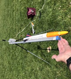
Adapting a Camera Tripod for a Rail Launcher
Continued from page 2
                                                                      Start by disassembling the threaded mount that fits into
                                                                 the camera mount plate of the tripod. In my case, the small
                                                                 “silver” knob actually is threaded to the end of the longer
                                                                 thread extending through the plate and up into the camera
                                                                 base. Then off came the larger nylon wheel with a pressed-
                                                                 in-place nut.

                                                                     An examination of the curved “stem” from the tripod
                                                                 adjustment head – the bigger part that allows it to pivot
                                                                 and tilt – showed this to be a casting with radius curves on
                                                                 the stem to camera plate and the round “boss” that holds
                                                                 the “captured” longer camera mount threaded rod. Those
                                                                 impact some of the next steps.

                                                                      Measurements count!
                                                                 {Photo 4} Of particular
                                                                 note for this step is the
                                                                 width of the “stem” where
                                                                 it meets the camera mount
                                                                 plate and the diameter
                                                                 of the cast “boss” in the
                                                                 center. For this assembly,
                                                                 the main brace has to fit
                                                                 “under” the camera mount
                                                                 plate – hence the brace
 Figure 3: Tripod Rail Camera Mount As-Is
                                                                 must be trimmed to fit both
      Tripod head – as in {Photo 3}                              the “stem” and the “boss”.
      [NOT ALL Camera tripod mount plates are the same!          Marking the dimensions on
  So adapt the below as necessary for your particular tripod!]   the brace is shown. {Photo
  My first thought was simply to bolt a 90° angle plate onto     5} NOTE! This particular
  the camera hold down thread. You quickly find out the          design mounts the rail to
  moment arm of the 1010 rail will overcome this sort of         one side of the camera
  connection. Instead, I went with a clamping arrangement        mount plate – not over one      Figure 4: Tripod Rail
  that captured the entire camera mount plate between two        of the ends!                    Camera Mount Measure
  90° angle plates. [See photo #16]
                                                                                                    Continued on page 4

Page 3                                                                                     Issue 566 / Feb. 1st, 2022
Adapting a Camera Tripod for a Rail Launcher
Continued from page 3

                                                                      Figure 6: Tripod Rail Head Stem Clearance
 Figure 5: Tripod Rail Mount Main Brace Mark Up

        I used a hacksaw to start the cut for the “stem” pocket,
  then a small grinder to remove the metal, creating a long
  rectangular slot. [Photo 6} The existing large hole in short
  leg of the main brace was a near perfect fit for the “boss”
  (got lucky there) - but both the slot and hole needed to be
  chamfered with a 45º relief to fit the radius of the casting
  edges so that the main brace plate fits tight to the bottom of
  the camera mount plate. This is done with a half-round or
  third circular ½” bastard file. {Photo 7} A bit of trial and re-
  fitting is likely needed to get a good tight fit to the underside
  of the camera mount plate. {Photo 8}

       Next, the inside brace is fitted to the top of the camera
  mount plate and the three parts clamped into position.
  {Photo 9} There is a ½” hole in the interior plate already.
  Now I simply used a permanent marker to color the location
  of that hole onto the main brace interior. Removing the
  parts, I use a centerpunch {Photo 10} to mark the location          Figure 7: Tripod Rail base thread cast boss clearance
  for an almost ¼” hole for the carriage bolt. The actual drill
                                                                                                            Continued on page 5

                                                    www.ApogeeRockets.com/Building_Supplies/Parachutes_Recovery_Equipment/Shock_Cord

Page 4                                                                                            Issue 566 / Feb. 1st, 2022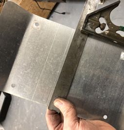
Adapting a Camera Tripod for a Rail Launcher
Continued from page 4

                                     size used was a #7 or
                                     13/64th so I could use a
                                     proper sized tap later. You
                                     could use a 3/16th drill as
                                     well, but be careful with
                                     the tap!

                                         As the brackets are
                                    stamped steel, you may
                                    find them “work hardened”
                                    and so a center punched
                                    start, good sharp bit, some
                                    cutting oil and a proper
                                    slow speed to the drill will
                                    make these holes go much
                                    easier – take your time or      Figure 9: Tripod Rail Inside Brace Clamped
                                    a drill bit will be broken!
                                    If you are using the right
                                    speed and pressure, you
                                    will see small curls or
 Figure 8: Tripod Rail Main         chips of cuttings come
 Brace Fitted                       from the flutes of the drill.

     Using a shop square, I lined up a second identical hole
  near the top of the main bracket. This one will fit a second
  ¼-20 bolt and align the 1010 rail.

      After the holes were drilled, a ¼-20 tap {Photo 11} was
  used to create threads through the main bracket. [That is
  why the hole is very slightly undersized] Again, cutting oil is
  the secret to getting a good clean thread from the tap.

       Now you need to get the ¼-20 carriage bolts reshaped         Figure 10: Tripod Rail Main Brace Pre-drill
  slightly to fit into the channel of a 1010 rail. Depending
                                                                                                       Continued on page 6

                                                                                                  ApogeeRockets.com/TARC

Page 5                                                                                       Issue 566 / Feb. 1st, 2022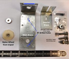
Adapting a Camera Tripod for a Rail Launcher
Continued from page 5

                                     on the bolts you get,
                                     they might just fit – but
                                     probably need to be filed
                                     flat on two edges {Photo
                                     12}. Here too, a bit of trial
                                     fitting is needed. The bolts
                                     should just slide into the
                                     rail {Photos 13 & 14}.
                                                                     Figure 12: Tripod Rail ¼ 20 Carriage Bolts filed
                                           The last part to be
                                     fabricated is the blast
                                     shield holder. In my case
                                     an old aluminum license
                                     plate was fitted for a 6”
                                     X 6” piece of ceramic
                                     tile. The tile lasts nearly
                                     forever, and does not
                                     conduct electricity in
                                     case your starter clips
                                     are resting on it. Any
                                     easily bent .020 steel or
                                     aluminum sheet metal            Figure 13: Tripod Rail        Figure 14: Tripod Rail Bolt
 Figure 11: Tripod Rail Tap-         would work for this – 6”        Bolt fitted                   slides in
 ping ¼-20 hole                      wide by 9” long.

      I simply used a vice as a metal brake and folded up a
  bottom lip to fit the tile thickness, then scored two lines for
  the size of the tile and a place for a hole to bolt the blast
  shield to the rail {Photo 15}.

                                                                     Figure 15: Tripod Rail Blast Deflector
 Figure 21: Tripod Rail Assembly                                                                        Continued on page 7

Page 6                                                                                         Issue 566 / Feb. 1st, 2022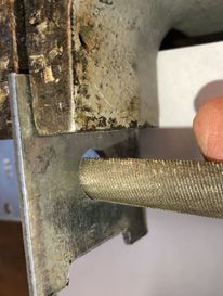
Adapting a Camera Tripod for a Rail Launcher
Continued from page 6
                                                                       One tip - {Photo X - Tripod Rail Zip-Tie Trick} I always
                                                                  have a few small zip ties in my range box. They are like
                                        Assembly starts with      masking tape for some applications. At the launch site, I zip
                                   the main bracket over          them around the 1010 rail to hold the alligator clips wires
                                   the threaded rod, the          to the launcher so there is no tension on the starter in the
                                   interior bracket on top of     motor, and I use a second one to act as a block or stop
                                   that same rod, the ¼-20        for the rail button or rail guide on the rocket, positioning
                                   Flange nut to tie them         the nozzle near the clips and the blast plate, but giving
                                   together and the threaded      me room to work. That upper zip-tie should be just snug
                                   nylon wheel to tighten         enough be repositioned if you are careful and used for
                                   those bits together. The       different rockets button / rail-guide positions.
                                   small silver threaded cap
                                   finishes it off – probably         I carry the tripod
                                   not a key need.                launcher to my site
                                                                  as one assembly, not
                                          Now the two ¼-20        removing or re-installing
                                     carriage bolts are screwed   the rail, although it can
                                     through the two threaded     be done easily with an
                                     holes from the “outside”     adjustable wrench.
                                     of the main brace and
                                     snugged tight. Make               Set-up consists of
                                     sure the flats are lined     extending the tripod legs
                                     up for the 1010 rail slot.   and locking them. If a
 Figure 16: Tripod Rail              Fortunately, the square      leg does not feel secure,
 Assembly                            head on my bolts was just    a zip-tie secured to the
  right for the needed clearance, but snug enough to keep         smaller diameter tube
  the rail from simply sliding on too easily.                     to the rescue! Don’t use
                                                                  tape, it makes a mess
      Laying the assembly flat on the workshop floor makes        for later.
  inserting the 1010 rail easier. If the rail is too tight on                                   Figure 17: Tripod Rail tilted
  the main mounting plate, you might need to back off the              Once the alligator        for load
  carriage bolt ½ turn.                                           clips cable from the
                                                                  launch controller / battery is in place and zip-tied, the rocket
      Add ¼-20 nuts to the interior of the assembly, mounting     is prepped, and the rail tipped over nearly 90° and the
  the blast shield support in the process. Tighten as needed      rocket slid onto the rail. [Photo 17} Wow is that easy! Pivot
  and you are done! {Photo 16}
                                                                                                     Continued on page 8

         www.ApogeeRockets.com/Building_Supplies/Parachutes_Recovery_Equipment/Parachutes

Page 7                                                                                        Issue 566 / Feb. 1st, 2022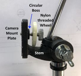
Adapting a Camera Tripod for a Rail Launcher
Continued from page 7

                                                                         This launcher has been
                                                                    used for two years now with
                                                                    no issues or modifications.
                                                                    The largest rocket launched
                                                                    was a mid-power design
                                                                    with “F” engine {Photo
                                                                    19}. It should be robust
                                                                    enough for most sport and
                                                                    mid-power rocket launches.
                                                                    Clearly heavier high-power
                                                                    rockets need proper ground
                                                                    support equipment. The
                                                                    tripod is not sturdy enough
                                                                    for a high-power rocket,
                                                                    and likely will fall over very
                                                                    easily. Be SAFE!
                                                                                                           Figure 19: Tripod Rail w/
                                                                   Parts List                              Hi-Flyer XL single stage

                                                                                                                                     Est.
                                                                    Qty   Nomenclature                     Source
                                                                                                                                     Cost
                                                                          1010 Framing       https://www.grainger.com/product/80-
                                                                    1                                                                $32
                                                                             rail – 6’      20-Framing-Extrusion-10-Series-2RCP8
 Figure 18: Tripod Rail tilted for load
                                                                                                                                     $10 –
                                                                    1      Photo Tripod        Thrift Shops – Craig’s List – etc.
                                                                                                                                    or free!
  the rail to the launch angle, then rotate the head as desired,                             Home Depot – UTDL5 G90 Concrete
                                                                    1      Main Brace                                                 $5
  install the ceramic blast shield and you are ready for launch                                           Angle
  {Photo 18}.                                                       1     Interior Brace    Home Depot – UBL3 G90 Corner Brace        $4
                                                                          ¼ - 20 1” Car-
                                                                    2                              Home Depot pack of 12              $4
                                                                           riage bolts
                                                                          ¼ - 20 Nuts for
                                                                    2                               Included in pack of 12             --
                                                                              above
                                                                          ¼ - 20 Flange
                                                                    1                                     Pack of 2                   $2
                                                                               Nut

                                                                                Apogeerockets.com/ZephyrJr

Page 8                                                                                            Issue 566 / Feb. 1st, 2022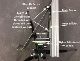
Fabled Flyer Rocket Plan
Download the RockSim design file for the Fabled Flyer at:
https://www.apogeerockets.com/Peak-of-Flight-Rocket-Plans
Fabled Flyer Parts List
10086 - (1) AT-18/18” (6pk)
10131 - (1) AT-33/18” (6/pk)
13028 - (1) CR-13/18 (2/pk)
13032 - (1) CR-18/24 (6pk)
13052 - (2) 1/8” Launch Lug 1” Long (6pk)
13404 - (1) CR-18/33 Cardstock (4/pk)
14099 - (1) Balsa
Sheet 1/8” x 3” x 18”
20068 - PNC-33MM (BT-55) (2/pk)
24046 - Regular “D” Crimped Engine Hook (6/pk)
29121 - 12” Parachute Pack
30325 - 100# Kevlar Shock Cord (per foot)
41100 - Fabled Flyer Decal Sheet
Order parts at:
https://www.apogeerockets.com/Quick_Order
Build Notes
• Refer to the Advanced Construction video series
on how to build a rocket from plans - https://
www.apogeerockets.com/Advanced_Construc-
tion_Videos/Rocketry_Video_287 to help in
building this kit.
• The only suggestion we have on this rocket is
to “paper” the fins for extra strength. The grain
direction on the rear portion that hangs down,
is sort of weak. It could snap on a hard landing.
You can see the papering technique in Ad-
vanced Construction Video #16 (https://www.apogeerockets.com/Advanced_Construction_Videos/Rocketry_Video_16).
Fabled Flyer By Tim Van Milligan
About the Design
The backstory on this rocket is that it was one of the prototypes for a new Apogee rocket kit. Our goal in this case, was to
make a simple skill-level-one design that people would find easy-to-build. When we make kits, we often do several concepts
for the decals and the overall color scheme. Of the many design choices for the new kit, it came down to two options: the
Fabled Flyer, or the Habu (https://www.apogeerockets.com/Model-Rocket-Kits/Skill-Level-1-Model-Rocket-Kits/Habu). It was
really a tie vote amongst our staff for which one would go in production. It came down to a coin-flip, and the Habu won.
But we liked the Fabled Flyer as well, so we decided to make it into a newsletter plan that people could build themselves.
You’ll find the only major difference between the Fabled Flyer and the Habu is the shape of the fins and the decals. Originally,
they had the same fin shape, but we modified the Fabled Flyer for this plan just to make it a bit different. In actuality, the
Fabled Flyer is actually released before the Habu!
Continued on page 10
Page 9 Issue 566 / Feb. 1st, 2022
Fabled Flyer Rocket Plan
Continued from page 9

    Side View                                        5.3in

                                                                             1in

                                                             12.1in

                                      14.3in

                             15.9in                                     1in
                                                                      (2 places)

                                               9in

Rear View
120°              Ø1.325in

                        Ø.736in
                                                                       1in

                                                                             Continued on page 11

Page 10                                                           Issue 566 / Feb. 1st, 2022
Fabled Flyer Rocket Plan
Continued from page 10
Fin Template
1 inch
Continued on page 12
https://www.youtube.com/c/apogeerockets
Page 11 Issue 566 / Feb. 1st, 2022Fabled Flyer Rocket Plan Purchase Decals
Continued from page 11 You can print the below decals or purchase printed decals here:
https://www.apogeerockets.com/Building-Supplies/Replacement-Parts-
for-Kits/Replacement-Decals/Fabled-Flyer-Newsletter-Plan-Decal
Body Tube Decals
White; body tube
1 inch
Fin Decals
White; 6 total, one for each side of the fin
Apogeerockets.com/X15
Page 12 Issue 566 / Feb. 1st, 2022You can also read