Infiniium MXR-Series See More. Do More. Save Time - Keysight
←
→
Page content transcription
If your browser does not render page correctly, please read the page content below
Infiniium MXR-Series
See More. Do More. Save Time.
You want your design to shine, and that means seeing more signals in
new ways. Be ready with a Keysight Infiniium MXR-Series oscilloscope:
it’s your window into the intricate interactions of complex designs. Get
from symptom to resolution fast by coupling the efficiency of an 8-in-1
bench solution with unprecedented simultaneous 8 channel performance.

Find us at www.keysight.com                                                Page 1
Contents
Meet the Infiniium MXR-Series .......................................................................................................................................... 3
   See More in the Time Domain with Eight Analog Channels ............................................................................................4
   See More with World-Class Signal Integrity.................................................................................................................... 4
   See More Information with History Mode and Segmented Memory.................................................................................5
   See More in the Frequency Domain with Real-Time Spectrum Analysis .........................................................................5
   Do More with 8-in-1 Instrument Integration..................................................................................................................... 6
   Save Time with Groundbreaking ASIC Technology ........................................................................................................ 7
   Save Time with the All New Fault Hunter Application ..................................................................................................... 7
   Completely Upgradeable ............................................................................................................................................... 8
Comprehensive Testing Applications ................................................................................................................................. 9
   Signal Integrity Testing .................................................................................................................................................. 9
   Power Supply, Rail, and PMIC Testing......................................................................................................................... 12
   Industry Specific Protocol Testing ................................................................................................................................ 14
   Compliance Testing ..................................................................................................................................................... 15
   RF Testing................................................................................................................................................................... 16
Analyze, Document, and Share Data Remotely ............................................................................................................... 17
Explore the Keysight Real-Time Oscilloscope Portfolio .................................................................................................... 17
Performance Characteristics ........................................................................................................................................... 18
Ordering Guide and Upgrade Information ........................................................................................................................ 29
   Standard accessories .................................................................................................................................................. 29
   Main model configuration ............................................................................................................................................. 30
   Probes and accessories............................................................................................................................................... 31
   Analysis software packages ......................................................................................................................................... 32
   Protocol decode and trigger software packages ........................................................................................................... 32
   Protocol compliance packages..................................................................................................................................... 32
   Offline testing .............................................................................................................................................................. 33
   Post-purchase upgrades .............................................................................................................................................. 34

           Find us at www.keysight.com                                                                                                                                 Page 2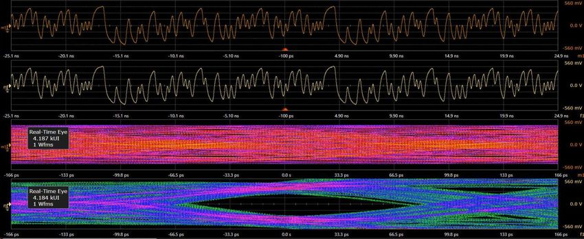
Meet the Infiniium MXR-Series
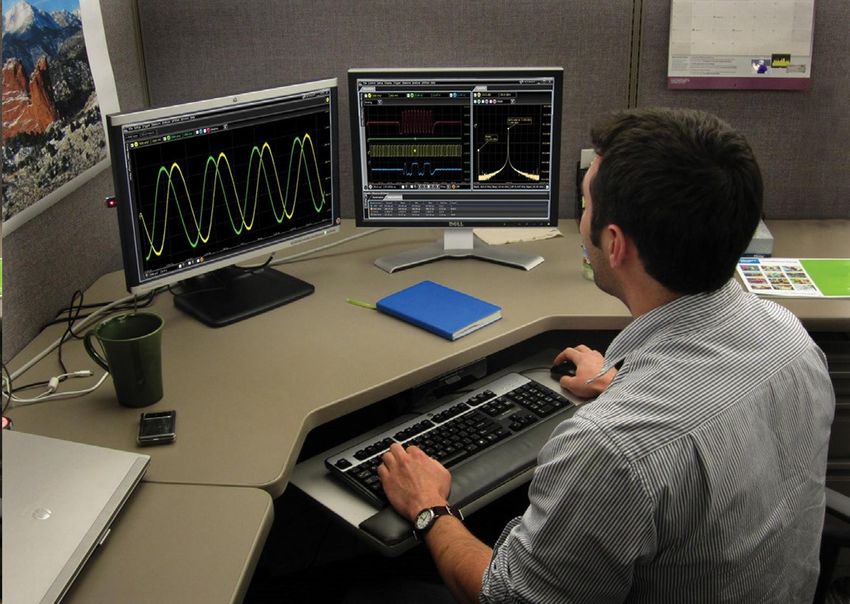
Welcome to the all-new Infiniium MXR-Series. With twelve models ranging in performance from 500 MHz
to 6 GHz, 4 or 8 analog channels, and dozens of hardware and software options, the Infiniium MXR-Series
is designed to meet your needs today. And with a platform that is fully upgradeable – with no exceptions -
it will be ready for your measurement needs tomorrow.
Infiniium MXR-Series Specifications Model Numbers 4 Channels 8 Channels
Analog channels 4 or 8, upgradeable 500 MHz MXR054A MXR058A
Bandwidth 500 MHz to 6 GHz, upgradeable 1 GHz MXR104A MXR108A
Sample rate 16 GSa/s 2 GHz MXR204A MXR208A
Memory 200 Mpts, upgradeable to 400 Mpts 2.5 GHz MXR254A MXR258A
Resolution 10 bits, up to 16 with high resolution 4 GHz MXR404A MXR408A
ENOB As high as 9.0 6 GHz MXR604A MXR608A
Timebase accuracy 8 parts per billion
Intrinsic Jitter As low as 118 fs Integrated Tools Option
Noise (1 mV/div) As low as 43 µV 16 digital channels MXR2MSO
Digital logic channels 16, dedicated input, upgradeable 50 MHz waveform generator MXR2WAV
Integrated tools 8-in-1 RTSA, DDC MXR2RTSA
Eye diagram speed >750,000 UI/s 4 digit DVM, 10 digit counters Standard
Screen display 15.6” touch, full HD, dual screen support Protocol analysis Various
Find us at www.keysight.com Page 3
See More in the Time Domain with Eight Analog Channels
The Infiniium MXR-Series is the first oscilloscope to offer 6 GHz bandwidth and 16 GSa/s sample rate on
every single one of its eight channels. Combined with being the first oscilloscope with 200 Mpts of
standard memory per channel, flexible three-stage triggering, over 50 standard measurements, a massive
library of application specific packages, and ASIC-accelerated testing, the Infiniium MXR-Series lets you
see more of your signal than ever before.

See More with World-Class Signal Integrity
Each model incorporates a 10-bit ADC with a sample rate of 16 GSa/s available on all channels
simultaneously. A high-resolution ADC’s usefulness is dependent on the low-noise front end that supports
the additional quantization levels. Our low noise front end includes custom ICs, like the 130 nm BiCMOS
IC that incorporates user-selectable analog filters and bandwidth upgrades via a software license. This
gives you:

•   4 times more vertical resolution than 8-bit oscilloscopes
•   Up to 16 bits with high-res mode
•   As low as 43 µV of noise, 9.0 bits system ENOB with hardware filtering

Find us at www.keysight.com                                                                                 Page 4
History Mode                                       Segmented Memory

                                                                               \

      see previous waveforms                                           arm for future waveforms

See More Information with History Mode and Segmented Memory
The Infiniium MXR-Series comes standard with two useful tools that allow you to look forward and
backward in time. With history mode, simply stop the oscilloscope at any time to review up to 1,024
previous trigger events. With segmented memory, you can capture up to 5,205 events post-trigger for
analysis, with no limit between events. If your design has an elusive event that only seems to happen
when you’re not around, these tools can help you arm the oscilloscope to look for it, then let you review
what gets captured at your leisure. And with a full HD screen of 1920x1080 pixels, and support for a
second, independent external monitor, that data can be organized and displayed however is best for you.

See More in the Frequency Domain with Real-Time Spectrum Analysis
Perform powerful RF analysis with up to 8 phase-coherent channels, all at once. Digitally down-convert
data on all 8 channels simultaneously with an analysis bandwidth up to 2 GHz. The RTSA view in the
Infiniium MXR-Series provides spans from 40 MHz to 320 MHz. In this image, we’re viewing (clockwise)
local US radio stations (~100 MHz), 2.4 GHz WLAN channel 1, 5 GHz WLAN channel 157, and Bluetooth
all at once. And since the data is from the analog channel inputs, they are phase coherent by definition,
with only a standard calibration required to ensure accuracy. And with a maximum frequency range of
6 GHz, the Infiniium MXR-Series easily supports applications from ZigBee to 5G FR1.

Find us at www.keysight.com                                                                                 Page 5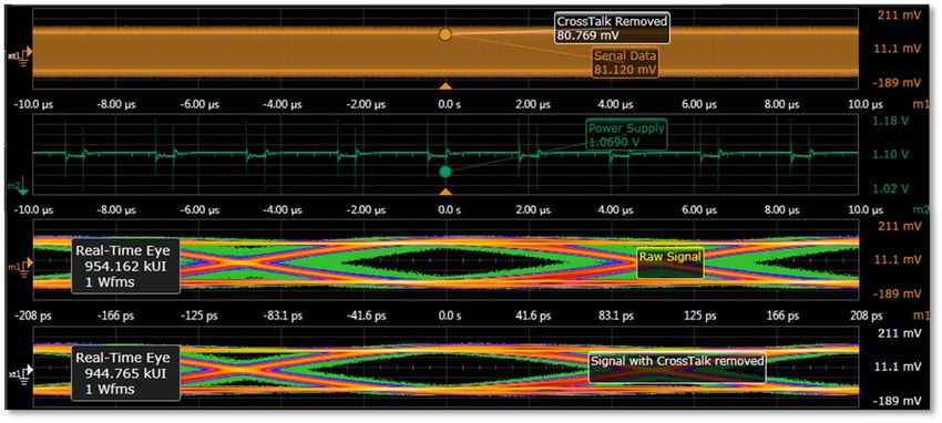
Do More with 8-in-1 Instrument Integration
        The Infiniium MXR-Series is more than just an oscilloscope -
        it’s 8 instruments in 1. Keysight Technologies, Inc. pioneered
        multiple-instrument integration with the release of the mixed
        signal oscilloscope (MSO) in 1996. The InfiniiVision
        2000/3000/4000X-Series took the concept to the next level
        by integrating five instruments in one in 2011. The Infiniium
        MXR-Series now integrates eight instruments in one to
        establish a new integration standard, with the first ever real-
        time spectrum analyzer on an oscilloscope.

                                                                                         Product sizes to scale!

        •     Oscilloscope                                     •    Waveform generator                                •    Phase noise testing
        •     Logic analysis                                   •    Frequency response
        •     Real-Time Spectral Analysis                      •    Digital voltmeter
        •     Serial protocol analysis                         •    Triple counters with totalizer

Generating a 10 MHz sine wave with frequency modulation, while measuring two signal frequencies with counters and a third signal's DC voltage with the DVM. Note that
                                               channels need not be enabled for the counter and DVM to operate.

        Find us at www.keysight.com                                                                                                                         Page 6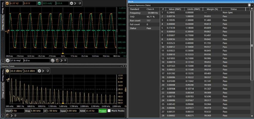
Save Time with Groundbreaking ASIC Technology
The Infiniium MXR-Series leverages a 100M+ gate CMOS
ASIC from our UXR-Series oscilloscope, and acts as an
“oscilloscope on a chip”. With many core oscilloscope features
done in hardware, performance of some features improved by
100x or more over previous generations, including:

•   Triggering and plotting: 200x faster
•   Eye diagrams: 50x faster
•   FFT plotting: 400x faster
•   Waveform averaging: 120x faster
•   And more!

In these images to the right, the fast trigger rate of >200,000
waveforms per second means seeing the runt on screen is
instantaneous, even though it occurs only on 0.02% of pulses.
Fast triggering lets you see rare events more readily, reducing
test time by avoiding the usual tricks like infinite persistence to
capture rare events. Eye diagrams are plotted at speeds over
750,000 UI per second, meaning six-sigma can be achieved
in mere seconds. And below, RTSA’s speed of 400,000 FFT
plots per second mean that even this bursty Bluetooth data is
captured easily, while nearly invisible with usual FFT (~1,000
plots per second).

                  Highly dynamic Bluetooth data is difficult to capture consistently with standard FFT (right), but easy with RTSA (left).

Save Time with the All New Fault Hunter Application
                                                                                                         Fault Hunter is a new and innovative
                                                                                                         expert system for inspecting digital
                                                                                                         systems. It automatically evaluates
                                                                                                         your signal’s characteristics against
                                                                                                         user definable criteria, quickly finding
                                                                                                         and saving errors for your review. It’s
                                                                                                         flexible, and you can define the test
                                                                                                         duration from 60 seconds up to
                                                                                                         48 hours. Set up your device under
                                                                                                         test on a Friday afternoon, and return
                                                                                                         Monday morning with a full test report
                                                                                                         to review, with billions of tests
                                                                                                         complete.

Find us at www.keysight.com                                                                                                                  Page 7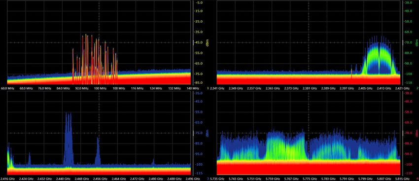
Completely Upgradeable
Today’s project requires 4 channels of 1 GHz
analysis bandwidth. What if your next project needs          Post-Purchase Upgrades          Model
8 channels, and 6 GHz of analysis bandwidth? And
a waveform generator? And compliance testing?         Add analog bandwidth, up to 6 GHz   MXR2BW
No problem with the Infiniium MXR-Series, which is
                                                      Add analog channels, 4 to 8         MXR28CH
fully upgradeable – no exceptions.
                                                      Add memory, 400 Mpts/ch             MXR2MEM
The Infiniium MXR-Series is the world’s first
benchtop oscilloscope to offer an upgrade from 4 to   Add RTSA and DDC                    MXR2RTSA
8 analog channels. Along with this, you can
upgrade bandwidth, memory, integrated equipment,      Add RF Frequency Extension, 6 GHz   MXR2FRE
applications and more after purchase, with just a     Add waveform generator, 50 MHz      MXR2WAV
license key. No matter how your needs change, the
Infiniium MXR-Series protects your investment by      Add MSO, 16 channels                MXR2MSO
growing with your lab’s needs of tomorrow.

Find us at www.keysight.com                                                                          Page 8
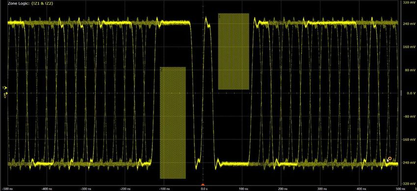
Comprehensive Testing Applications
Signal Integrity Testing
As data rates go up, the
signal deteriorates from the
transmitter to the receiver
due to ISI, noise, and other
factors. A high data rate
coupled with a lossy channel
will cause an open eye at a
transmitter to be closed at the
receiver. As eyes get more
and more closed, it ultimately
leads to significant data corruption and errors. Being able to analyze and find the root cause of these
problems can help you develop a more robust design, leading to shorter time to market and lower failure
rates in the field. The Infiniium MXR-Series offers applications of various levels of depth to help you get
the answers you need to improve your design.

InfiniiScan Advanced and Zone Triggering – D9010SCNA

This package allows you to create a three-stage trigger to identify signal integrity issues that hardware
triggering is unable to find in your electronic designs. This innovative software scans through thousands
of acquired waveforms per second to help you isolate signal anomalies, saving you precious
troubleshooting time. Trigger by drawing on-screen regions for a signal to hit or miss, or based on
measured parameters.

Find us at www.keysight.com                                                                                   Page 9
Vertical, Timing, and Phase Noise Analysis – D9010JITA

This package offers advanced statistical analysis of high-speed digital interfaces in the vertical (voltage)
and horizontal (time) domains, as well as phase noise analysis. The result: the industry’s most complete
jitter and noise analysis software for real-time oscilloscopes.

De-embedding – D9010DMBA

This package includes PrecisionProbe and InfiniiSim Basic, two tools designed to de-embed the effect of
cables and fixtures from measurements. PrecisionProbe allows you to characterize the response of a
probe, cable or fixture; InfiniiSim lets you model them out of a measurement.

Find us at www.keysight.com                                                                                    Page 10
Equalization and Crosstalk – D9020ASIA

This package is intended for anyone working in high speed digital applications where eyes are closed.
Equalization, InfiniiSim, and Crosstalk/Power Integrity packages enable deep analysis as to why an eye is
closed, what it will take to open it, and simulating the results.

PAM-3 and PAM-4 Analysis – D9010PAMA

This package quickly sets up clock recovery and measurements for a PAM encoded signal. The software
is also able to accurately set the individual threshold levels of your PAM signal and render each individual
eye. It also includes BER/SER measurements and statistics.

Find us at www.keysight.com                                                                                    Page 11
Power Supply, Rail, and PMIC Testing
The increased functionality, higher density, and higher
frequency operation of many modern electronic products
has driven the need for lower supply voltages. It is
common in many designs today to have 3.3, 1.8, 1.5, and
even 1.1 V DC supplies—each of them having tighter
tolerances than in previous product generations.

Power supply induced jitter (PSIJ) can be one of the
largest sources of clock and data jitter in digital systems.
Similarly, noise on DC supplies is often caused by
switching currents from the transitions of clock and data
in these systems. Wouldn’t you like a relatively easy
method of determining how much of your systems’ data
jitter is PSIJ and/or how much of the noise on the DC
supplies is coming from specific clocks, data lines or
other toggling sources? We’ve got the tools for that in the
Infiniium MXR-Series.

Switch Mode Supplies – D9010PWRA

This application enables a broad range of automated power supply characterization measurements from
input analysis, switching device characterization, and output analysis. It also includes critical frequency
response measurements such as power supply rejection ratio (PSRR) and control loop response.
Additionally, users can create Bode plots from DC to 50 MHz, both magnitude and phase, with
D9010PWRA. See the data sheet for more.

Find us at www.keysight.com                                                                                   Page 12
Power Rail and PMIC Integrity – D9010POWA
This application is a tool for analyzing power supply induced jitter or switching current loads on a DC
supply, and can analyze adverse interactions and their effects without the need for simulation or complex
modeling. Together with the N7020A or N7024A Power Rail Probe, you have an even more powerful
means of measuring and analyzing power integrity. And with standard mask testing on every channel,
automatic delta time measurements, and a flexible user interface, PMIC analysis is simpler than ever.

           By simulating a power supply with less noise, we can realize much wider eye diagrams, leading to more robust transfer of data.

   With waveforms separated into grids and independent mask tests possible on every channel, you can continuously test these six power rails over
                                                          thousands of startup cycles.

Find us at www.keysight.com                                                                                                                         Page 13
Industry Specific Protocol Testing
Our protocol trigger and decode packages make easy to debug and test digital designs. Get access to a
rich set of integrated protocol level triggers specific to each serial bus. When serial triggering is selected,
the application enables special real-time triggering hardware inside the scope. Hardware-based triggering
ensures that the scope never misses a trigger event when armed. This hardware takes signals acquired
using either scope or digital channels and reconstructs protocol frames. It then inspects these protocol
frames against specified protocol-level trigger conditions and triggers when the condition is met.
Package Description Data Sheet
2 2
I C, SPI, Quad SPI, eSPI, Quad eSPI, RS232, UART, JTAG, I S,
Low Speed Serial SVID, Manchester D9010LSSP
Embedded USB 2.0, 10/100 Mb/s Ethernet, USB-PD, PCIe Gen 1 (decode) D9010EMBP
Low Speed Automotive CAN, LIN, CAN-FD, SENT, FlexRay D9010AUTP
3
MIPI Low Speed RFFE, I C, SPMI D9010MPLP
MIPI C-PHY, D-PHY C-PHY/D-PHY based CSI & DSI (Up to 2.5 Gbps) D9010MCDP
MIPI M-PHY CSI 3, DigRFv4, LLI, UniPro, UFS, SSIC (Up to Gear 1 Speed) D9010MPMP
Military ARINC 429, MIL-STD 1553, SpaceWire D9010MILP
High Speed Automotive 100BASE-T1 Automotive Ethernet D9020AUTP
USB USB 2.0, USB-PD, eUSB2, USB4 LS (decode) D9010USBP
Includes D9010LSSP, D9010EMBP, D9010MPLP, D9010MILP,
Infiniium Basic Bundle D9011BDLP
D9010AUTP
Find us at www.keysight.com Page 14Compliance Testing
Compliance test applications on the Infiniium MXR-Series provide a fast and effortless way to validate
that your designs meet industry standards. They save you time and money by automating the task of
preforming compliance measurements based on the latest requirements. These test application offers a
user-friendly setup wizard and a comprehensive report that includes margin analysis.
Standard Description Min. BW Data Sheet
USB 2.0 USB 2.0 Transmitter 2 GHz D9010USBC
Ethernet 10M/100M/1GBASE-T and Energy Efficient Ethernet 1 GHz D9010ETHC
Ethernet 10G, MG Base-T, N-Base-T 4 GHz D9010EBZC
1000BASE-T1 2.5 GHz
Automotive Ethernet 100BASE-T1 1 GHz AE6910T
10BASE-T1 500 MHz
C-PHY MIPI C-PHY, up to 1.5 Gbps 6 GHz D9010CPHC
D-PHY MIPI D-PHY, up to 1.5 Gbps (up to CTS v1.2) 6 GHz D9020DPHC
Find us at www.keysight.com Page 15RF Testing
With digital down-conversion (DDC) on every
channel, the Infiniium MXR-Series provides
you much more flexibility and affordability for
RF testing, as well as never before seen test
performance. Digitally down-converted data
can be displayed and measured on screen,
visualized in a Real-Time Spectrum Analyzer
(RTSA) mode, or exported to PathWave
Vector Signal Analysis (89600 VSA) for
further measurements. All models come
standard with 40 MHz of analysis bandwidth
for DDC and RTSA on one center frequency,
with options for 160 or 320 MHz of analysis
on 4 or 8 different center frequencies.
And with our all new Frequency Extension option, the frequency range for DDC and RTSA is not limited to
the bandwidth of your oscilloscope. For example, if your measurement needs in the time domain only call
for 2 GHz of analog bandwidth, but you wish to analyze wireless data up to 6 GHz, you can purchase a 2
GHz Infiniium MXR-Series and still get 6 GHz analysis with DDC and RTSA. See specifications for details.
Configuration Frequency Range Analysis Bandwidth Center Frequency Control
Standard Performance 0 Hz to Oscilloscope Bandwidth 40 MHz All channels are locked together
RTSA: 160/320 MHz
+ RTSA/DDC Option 0 Hz to Oscilloscope Bandwidth Independent per channel
DDC: 2 GHz
+ RTSA/DDC Option RTSA: 160/320 MHz
0 Hz to 6 GHz Independent per channel
+ Frequency Extension Option DDC: 2 GHz
Find us at www.keysight.com Page 16Analyze, Document, and Share Data Remotely with Infiniium Offline
You depend on your oscilloscope to capture an
accurate picture of what’s happening in your design.
Ever wish you could do additional signal viewing,
analysis and documentation tasks away from your
scope and target system? With Infiniium Offline, now
you can. Infiniium Offline is a copy of the same
powerful software provided on the Infiniium MXR-
Series oscilloscope. You can capture waveforms on
your scope, save to a file, and recall the waveforms
into Infiniium Offline. In addition, the application
supports a variety of popular waveform formats from multiple oscilloscope vendors. Now you can view,
analyze, share, and document scope measurements anywhere your PC goes. Find model numbers in the
configuration guide at the end of this document.
Explore the Keysight Real-Time Oscilloscope Portfolio
Keysight engineers have been
creating reliable, insightful products
for more than 80 years. We are
continually looking for new ways to
help you shape the future with
innovative products and test
solutions. From high performance to
extreme value, and bandwidths
ranging from 50 MHz to more than
110 GHz, we have the oscilloscope
solutions to meet your evolving
needs. Below is a small sample of
our portfolio; check our website for
the latest information.
Product Series: 1000 X-Series 3000T X-Series MXR-Series V-Series Z-Series UXR-Series
4 or 8, 1, 2 or 4,
Analog channels 2 or 4 2 or 4 upgradeable 4 4 upgradeable
Bandwidth, all channels 200 MHz 1 GHz 6 GHz 16 GHz 33 GHz 110 GHz
Sample rate, all channels 1 GSa/s 2.5 GSa/s 16 GSa/s 40 GSa/s 80 GSa/s 256 GSa/s
Max memory, all channels 1 Mpts 2 Mpts 400 Mpts 2 Gpts 2 Gpts 2 Gpts
Resolution 8 bits 8 bits 10 bits 8 bits 8 bits 10 bits
Timebase accuracy 50 ppm 1.6 ppm 8 ppb 100 ppb 100 ppb 25 ppb
Intrinsic Jitter - - 118 fs 100 fs 50 fs 25 fs
Lowest noise (1 mV/div) - 113 µV 43 µV 210 µV 410 µV 150 µV
Max ENOB - - 9.0 6.6 - 6.8
Logic analysis - 16 ch. 16 ch. 16 ch. 16 ch. -
Hardware plotting Yes Yes Yes - - Yes
Screen display 7” WVGA 8.5” WVGA 15.6” Full HD 12.1” XGA 12.1” XGA 15.4” XGA
Find us at www.keysight.com Page 17Performance Characteristics
Analog channel specifications
MXR05xA MXR10xA MXR20xA MXR25xA MXR40xA MXR60xA
50 Ω [1] 500 MHz 1 GHz 2 GHz 2.5 GHz 4 GHz 6 GHz
Bandwidth (-3db)
1 MΩ 500 MHz 500 MHz 500 MHz 500 MHz 500 MHz 500 MHz
10/90% 860 ps 430 ps 215 ps 172 ps 107.5 ps 71.7 ps
Typical rise/fall time [4]
20/80% 620 ps 310 ps 155 ps 124 ps 77.5 ps 51.7 ps
Input channels 4 or 8 channels analog, 16 channels digital (optional)
Sample rate, real-time 16 GSa/s, all analog channels [1]
Sample resolution 62.5 ps (divide by interpolation factor, if enabled)
Vertical resolution [3] 10 bits, up to 16 bits with high-resolution mode
Real-time update rate >200,000 waveforms/sec
Standard 200 Mpts/channel, all channels
Memory depth [1]
Optional 400 Mpts/channel, all channels
50 Ω [1] ±3.5% (typically ±1% at 25 °C)
Input impedance
1 MΩ ±1% (14 pF typical)
50 Ω [1] 1 mV/div to 1 V/div
Input sensitivity [3]
1 MΩ 1 mV/div to 5 V/div
50 Ω [1] DC
Input coupling
1 MΩ DC, AC (>11 Hz)
Analog 20 MHz, 200 MHz
Bandwidth limit filters 14.7 MHz up to scope bandwidth, increments of one decimal point. Filter options: Brick
Digital [5]
Wall, 4th Order Bessel, or Bandpass
50 Ω ±5 VMAX [1]
1 MΩ 30 VRMS or ±40 VMAX (DC + VPEAK)
Max input voltage Probing technology allows for testing of higher voltages; the included N2873A 10:1
Notes probe supports 300 VRMS or ±400 VMAX (DC + VPEAK). No transient overvoltage allowed
in either the 50 Ω or 1 MΩ path, with or without probes.
≤55 mV/div: ±0.8 V
≤120 mV/div: ±1.6 V
50 Ω [1]
≤260 mV/div: ±3.2 V
Offset range >260 mV/div: ±4 V
200 mV/div: ±40 V
Offset accuracy [1][3] 2 V: ±0.1 div ± 2 mV ± 1.5%
Dynamic range [6] ±4 divisions from center screen
DC gain accuracy [1][2][3] ±2% full scale (±1% typical)
Dual cursor: ±[(DC gain accuracy) + (resolution)]
DC voltage measurement accuracy [2]
Single cursor: ±[(DC gain accuracy) + (offset accuracy) + (resolution/2)]
Adjacent Channels: ≤-60 dB (DC to 2 GHz), ≤-50 dB (2 to 6 GHz)
Channel-channel isolation
Non-Adjacent Channels: ≤-85 dB (DC to 2 GHz), ≤-65 dB (2 to 6 GHz)
1. Denotes warranted specifications, all others are typical. Specifications are valid after a 30-minute warm-up period and ± 5 °C from firmware calibration temperature. Input
impedance is valid when V/div scaling is adjusted to show all waveform vertical values within the oscilloscope display.
2. Full scale is defined as 8 vertical divisions. Magnification is used below 2 mV/div, full-scale is defined as 16 mV. Testing is at maximum sample rate.
3. 50 Ω input: The major scale settings are 5 mV, 10 mV, 20 mV, 50 mV, 100 mV, 200 mV, 500 mV, and 1 V per division. 1 MΩ input: The major scale settings are 5 mV, 10
mV, 20 mV, 50 mV, 100 mV, 200 mV, 500 mV, 1 V, 2 V, and 5 V per division. For a 10:1 probe, vertical scaling is multiplied by 10.
4. 10/90 calculation based on Tr = 0.43/BW. 20/80 calculation based on Tr = 0.31/BW.
5. You may adjust bandwidth limits up to the bandwidth of the scope when using Brick Wall filter. When using 4th Order Bessel , maximum bandwidth limit is roughly 2/3 the
bandwidth of oscilloscope. Bandpass is designed for use in our Phase Noise Analysis application and not designed for general purpose use. Contact Keysight if more
information is needed.
Find us at www.keysight.com Page 18High-resolution mode (standard)
Bits of resolution Sample rate Bandwidth [1]
10 Up to 16 GSa/s Up to 6 GHz
11 6.4 GSa/s 2.4 GHz
12 3.2 GSa/s 1.2 GHz
13 1.6 GSa/s 600 MHz
14 800 MSa/s 300 MHz
15 400 MSa/s 165 MHz
16 200 MSa/s 82.5 MHz
16 100 MSa/s 41.3 MHz
16 50 MSa/s 20.6 MHz
1. Up to bandwidth specified or oscilloscope model bandwidth, whichever is lower
RMS noise floor (V RMS AC) on 50 Ω inputs
Vertical setting 20 MHz [1] 200 MHz [1] 500 MHz [1] 1 GHz [1] 2 GHz [1] 2.5 GHz 4 GHz 6 GHz
1, 2 mV/div 43 µV 59 µV 63 µV 73 µV 91 µV 100 µV 132 µV 193 µV
5mV/div 40 µV 61 µV 70 µV 81 µV 102 µV 112 µV 149 µV 216 µV
10 mV/div 46 µV 69 µV 81 µV 99 µV 131 µV 144 µV 189 µV 251 µV
20 mV/div 59 µV 99 µV 122 µV 156 µV 209 µV 233 µV 297 µV 401 µV
50 mV/div 210 µV 278 µV 328 µV 401 µV 520 µV 569 µV 719 µV 971 µV
100 mV/div 452 µV 582 µV 681 µV 821 µV 1.06 mV 1.17 mV 1.46 mV 2.03 mV
1 V/div 2.95 mV 4.10 mV 5.07 mV 6.33 mV 8.4 mV 9.31 mV 11.91 mV 16.26 mV
1. High-resolution is used for bandwidths 2 GHz and below.
ENOB on 50 Ω inputs, 50 mV/div
20 MHz 200 MHz 250 MHz 350 MHz 500 MHz 1 GHz 2 GHz 2.5 GHz 3 GHz 4 GHz 5 GHz 6 GHz
9.0 8.5 8.4 8.3 8.2 8.0 7.6 7.5 7.4 7.2 7.1 6.8
High resolution on the Infiniium MXR-Series works like no other oscilloscope before it. Instead of setting
high-resolution bits automatically with no user control, you select ADC bits or a system bandwidth, and let
the scope optimize around that. This means the resolution of your data isn’t changing without your explicit
request. ADC resolution and bandwidth limit filters work in tandem to produce the best measurement
results possible.
All Infiniium MXR-Series scopes come from the factory calibrated to 6 GHz, and leverage brickwall filters
to achieve each model bandwidth. Thus, the noise and ENOB data above is applicable from 20 MHz up
to the bandwidth of your oscilloscope model when using the built-in global bandwidth limit feature.
Find us at www.keysight.com Page 19Analog channel specifications (horizontal)
Sample Mode Sequential sampling with up to 32-point sin(x)/x interpolation
Averaging 2 to 1,048,575 averages, up to 12,000 avg/sec (HW accelerated)
Oversamples at 16 GSa/s, saving min and max voltages, to detect glitches or
Acquisition modes Peak detect
aliasing
Segmented Up to 5,205 future acquisitions
History mode Up to 1,024 previous acquisitions
Roll mode Scrolls waveform across the display, right to left
Roll mode 50 ms/div to 1000 s /div
Timebase range Other modes 5 ps/div to 200 s/div
Zoom window 1 ps/div to current main time scale setting
Horizontal position range 0 s to ±200 s, Continuously adjustable
Main window 40 fs (granularity of horizontal position of waveform on screen)
Horizontal position resolution
Zoom window 8 fs
De-skew range ±1 ms, in steps of 100 fs
Time scale accuracy [1][7] ±(8 ppb initial + 75 ppb/year aging)
4 channel models 8 channel models
100 ns/div 118 fsRMS 150 fsRMS
Intra-channel intrinsic jitter, 1 µs/div 130 fsRMS [9] 156 fsRMS
4 channels [3][5] 10 µs/div 140 fsRMS [9] 172 fsRMS [10]
100 µs/div 145 fsRMS [9] 175 fsRMS [10]
1 ms/div 155 fsRMS [9] 181 fsRMS [10]
Inter-channel intrinsic jitter [3] 100 fsRMS
Inter-channel skew drift [3][6]Analog channel triggering
Edge Trigger on all analog channels, aux-in, power supply line
Trigger sources
Other Trigger operations as outlined below
Max edge trigger frequency (50 Ω) 6 GHz
Trigger level range ±4 divisions from center screen (auxiliary: ±5 V, max input 5 VPP)
Analog channels: see next table
Trigger sensitivity
Aux trigger input: 200 mVPP, DC to 3 GHz
Trigger hold off range 25 ns to 10 s, fixed or random
Trigger coupling DC, AC, LF reject (50 kHz HPF), HF reject (50 kHz LPF)
Sweep modes Auto, triggered, single
4 channel models: 523 fsRMS
Trigger jitter
8 channel models: 531 fsRMS
Minimum trigger re-arm time 2.5 GHz
< 5 mV/divAvailable triggers (standard, unless otherwise noted)
Trigger type Channels available on Description
Triggers on a specified slope (rising, falling or alternating between rising and
Edge Channels 1-8, digital, line, aux falling) and voltage level on any channel or auxiliary trigger.
Triggers on rising or falling edges that cross two voltage levels in > or < the
Edge transition Channels 1-4 amount of time specified. Edge transition setting from 75 ps to 10 s
The trigger is qualified by an edge. After a specified time-delay between 1.5
Edge then edge
Channels 1-4, digital ns to 20 s, a rising or falling edge on any one selected input will generate the
(time) trigger
The trigger is qualified by an edge. After a specified delay between 1 to
Edge then edge
Channels 1-4, digital 65,000,000,000 rising or falling edges, another rising or falling edge on any
(event) one selected input will generate the trigger
Triggers on a pulse that is wider or narrower than the other pulses in your
waveform by specifying a pulse width and a polarity. Pulse width range
Pulse width Channels 1-4, digital settings 75 ps to 20 s. Trigger point can be configured for “end of pulse” or
“time out”
Triggers on glitches narrower than the other pulses in your waveform by
Glitch Channels 1-8, digital specifying a width less than your narrowest pulse and a polarity. Glitch
range settings: < 75 ps to < 10 s
Triggers on a pulse that crosses one threshold but fails to cross a second
Runt Channels 1-4 threshold before crossing the first again. Can be time qualified with a range
of 75 ps to 10 s
Triggers the oscilloscope when the waveform has been at a higher voltage
than the voltage specified by the Level control for too long (High Too Long),
when the waveform has been at a lower voltage than the Level voltage for
Timeout Channels 1-4, digital too long (Low Too Long), or when the waveform has taken too long to pass
through the Level voltage (Unchanged Too Long). Timeout settings from 75
ps to 20 s.
Identifies a trigger condition by looking for a specified pattern or a pattern
Pattern/State Channels 1-4, digital and an edge (state) across the input channels
Triggers on violations of setup time, hold time, or both setup and hold time.
Setup / hold Channels 1-4 Setup times from 75 ps to 20 s and hold times from 75 ps to 100 ns.
Specifies a voltage range and then trigger when the waveform either exits
this range, enters this range, stays outside the range for too long or too
Window Channels 1-4 short, or stays inside the range for too long or too short. Range setting from
75 ps to 20 s.
Trigger on certain packets or patterns in protocol-based data.
Protocol Bus dependent
Requires a protocol trigger/decode option, for example D9010LSSP
Software triggers on NRZ or 8b/10b-encoded data up to 6 Gbps, up to 80-bit
pattern. Support multiple clock data recovery methods including constant
Generic Protocol Channels 1-8
frequency, 1st-order PLL, 2nd-order PLL, explicit clock, explicit 1st-order PLL,
explicit 2nd-order PLL, Fibre Channel, FlexRay receiver, FlexRay transmitter
Triggers on the Nth edge of a burst that occurs after an idle time from 1.5 ns to 20
Burst Channels 1-4
s.
Nth Edge Channels 1-8 Triggers on the Nth edge
OR’d Edges Channels 1-4 Identifies a trigger condition by looking for selected edges on up to four channels
Qualified trigger across up to 8 user-drawn zones. For each zone, user specifies
“must intersect” or “must not intersect.” Zones can be drawn on analog channels
InfiniiScan Zone Channels 1-8
and combined using Boolean logic.
Requires option D9010SCNA
Software triggers on the results of the measurement values. For example, when
the “time interval error (TIE)” is measured, InfiniiScan can trigger on a specific TIE
Measurement limit Channels 1-8, digital, line, aux
value.
Requires option D9010SCNA
Software triggers on the non-monotonic edge. The non-monotonic edge is
Non-monotonic edge Channels 1-8 specified by setting a hysteresis value.
Requires option D9010SCNA
Find us at www.keysight.com Page 22Fault Hunter (standard)
Auto Setup 30 second statistical measurement analysis of incoming signal
Result information Test failure automatically saved in memory. Fault condition can be copied to trigger for further testing.
Automatic identification of common digital signal errors: Positive glitch, negative glitch, slow rising edge, slow
Test results
falling edge, positive runt, negative runt
Measurements (standard, unless otherwise noted)
Maximum at once 20 in either main, zoom, or gated region (up to 16 gates)
Maximum rate >300,000 measurements/second (any number of measurements on, “measure all edges” enabled)
Amplitude, average, base, crossing point, maximum, minimum, overshoot and preshoot (as a percentage or
Voltage (analog) voltage), VPP contrast, peak to peak, pulse (amplitude, base, top), RMS, top, thresholds (lower, middle, upper),
voltage @ time
Rise time, fall time, period, frequency, pulse width (+/-), duty cycle, TMIN, TMAX, crossing point time, delta time,
Time (analog)
pulse count, bursts (width, period, interval), s/h time
Time (digital) Period, frequency, pulse width (+/-), duty cycle, delta time
Mixed (analog) Area, slew rate, charge. Requires N282xA probe
Frequency domain FFT frequency and magnitude, channel power, power spectral density, occupied bandwidth
Make timing measurements only when other input signal level conditions are true. Any channels not involved in a
Level qualification
measurement can be used to qualify all timing measurements. Requires D9010SCNA
Eye height, eye width, eye jitter, crossing percentage, Q factor, duty-cycle distortion
Eye diagrams
>750,000 UI/second (for eye diagrams, with hardware acceleration enabled)
Statistic modes Mean, standard deviation, minimum, maximum, count
Math (standard, unless otherwise noted)
Sources Any analog or digital channel, waveform memory, or other math functions
Maximum at once 16
Add, subtract, multiply, divide, FFT (magnitude and phase), absolute value, average, common mode,
Math
delay, differentiate, integrate, invert, max, min, square, square root
Filters High pass filter, low pass filter, smoothing
Amplitude demodulation, bus chart, envelope, gating, histogram, pattern average, measurement log,
Functions Visualizations
measurement trend, magnify / duplicate, XY mode (Z-Qualified)
Preinstalled scripts: Butterworth, FIR, LFE, RTEye, and SqrtSumOfSquare
User Defined: The input source data is passed to a MATLAB script you create. The processed data is
MATLAB
passed back to Infiniium to be displayed as a function.
Requires a MATLAB license
Range DC to Nyquist frequency
Horizontal Scale Linear, logarithmic
Vertical Units dBm, dBmV, dBuV, VRMS, Watts
FFT
Controls Start and stop frequency, span and center frequency, resolution bandwidth
Peak detect Automatically find and annotate up to 25 peaks of a user-defined level
Windows Flattop, rectangular, Hanning, Blackman Harris, Hamming
Sources Any waveform or measurement below
Histograms Orientation Horizontal (timing and jitter) or vertical (noise and amplitude)
Peak-to-peak, min, max, mean, median, mode, standard deviation, mean ±1σ/2σ/3σ, total hits, peak
Measurements
(area of most hits), bin width, FWHM (histogram width at half maximum)
Find us at www.keysight.com Page 23Waveform Generator (optional, specifications are typical)
Connector BNC, rear panel
Voltage range, 50 Ω 1 mVPP [1] to 5 VPP [2]
Voltage range, 1 MΩ 2 mVPP [1] to 10 VPP [2]
Presets TTL, CMOS (5 V), COMS (3.3 V), CMOS (2.5 V), ECL
Vertical resolution 100 µV
Vertical accuracy 2% (< 1 kHz)
Output Frequency resolution [3] 12.5 mHz
Square/pulse: 1 ppm (f ≥ 8 kHz), [f/25000] ppm (f < 8kHz)
Frequency accuracy [4]
Other waveforms: 1 ppm (f ≥ 5 kHz), 3 ppm (f < 5kHz)
Modes Normal, single shot (all but square, pulse, noise, DC)
DC, sine, square, pulse, triangle/ramp, noise, sinc, exponential rise/fall, cardiac,
Waveforms
Gaussian pulse, PRBS, arbitrary
Protection Overload automatically disables output
Isolation Not available, main output BNC is grounded
±(8 VDC – Peak AC) into 1 MΩ
Range
±(4 VDC – Peak AC) into 50 Ω
DC offset Resolution 100 μV or 3 digits, whichever is higher
Waveform modes: ± 1.5% of offset setting ± 1% of amplitude ± 1 mV
Accuracy
DC mode: ± 1.5% of offset setting ± 3 mV
Frequency range 12.5 mHz to 50 MHz
Amplitude flatness ± 0.5 dB (≤20 MHz), ± 1 dB (>20 MHz)
Harmonic distortion Harmonic distortion: -40 dBc [5]
Sine
SFDR Spurious (non-harmonic): -40 dBc [6]
THD 1% [7]
SNR 40 dB [8]
Frequency range Frequency range: 0.0125 Hz to 20 MHz
Duty cycle Duty cycle: 20 to 80%, resolution of 1% or 1 ns, whichever is larger
Pulse width Pulse width: 10 ns minimum, 1 ns resolution [9]
Square / pulse Rise/fall time Rise/fall time: 9 ns (10 to 90%)
Overshoot Overshoot: < 4%
Asymmetry (at 50% DC) ±1% ± 5 ns
Jitter (TIE RMS) 100ps [10]
Frequency range 12.5 mHz to 200 kHz
Triangle (ramp) Linearity 0.01
Symmetry 0 to 100%, 1% resolution
Noise Bandwidth 40 MHz
Sine Cardinal (Sinc) Frequency range 12.5 mHz to 1.0 MHz
Exponential Rise/Fall Frequency range 12.5 mHz to 10.0 MHz
Cardiac Frequency range 12.5 mHz to 200.0 kHz
Gaussian Pulse Frequency range 12.5 mHz to 5.0 MHz
Pattern length 2^7, 2^15, 2^23, 2^31
PRBS Bit rate 100 bps to 40 Mbps (speeds of 200 MHz divided by an integer value)
Encoding NRZ
Find us at www.keysight.com Page 24Waveform Length 1 to 122,070 points
Repetition Rate 12.5 mHz to 12 MHz
Arbitrary Sample Rate 200 MSa/s
Filter Bandwidth 40 MHz
On-screen editor; import/export of data to and from channels/memories, import/export
Editor
data to and from a file (.csv)
Types AM, FM, FSK
Carriers Sine, ramp, sine cardinal, exponential rise, exponential fall, and cardiac
Source Internal (no external modulation capability)
Profile sine, square, ramp
AM Frequency 1 Hz to 20 kHz
Depth 0% to 100%
Modulation Profile sine, square, ramp
Frequency 1 Hz to 20 kHz
FM Minimum carrier 10 Hz
Deviation 1 Hz to carrier frequency or (2e12 / carrier frequency), whichever
is smaller
Modulation 50% duty cycle square wave
FSK FSK rate 1 Hz to 20 kHz
Hop frequency 2 x FSK rate to 10 MHz
1. 10 mVPP (1 MΩ) / 5 mVPP (50 Ω) minimum if | DC + Peak AC | ≥ 400mV
2. 8 VPP (1 MΩ) / 4 VPP (50 Ω) maximum for Gaussian waveshape
3. Resolution is Freq/25000 Hz for square and pulse waveforms < 8 kHz
4. Include (add) external reference clock frequency error, if applicable
5. For amplitude ≤1 VPP at 50 MHz, ≤2 VPP at 40 MHz, ≤5 VPP at ≤30 MHz, into 50 Ω load. -30 dBc at 5 VPP, 50 MHz
6. For amplitude ≥5 mVPP into 50 Ω load
7. For amplitude ≤1 VPP at 50 MHz, ≤2 VPP at 40 MHz, ≤5 VPP at ≤30 MHz, into 50 Ω load. 4% at 5 VPP, 50 MHz
8. ≥35 mVPP, 0V offset, into 50 Ω
9. 5 nS if frequency is < 8kHz
10.
11.
Amplitude ≥20 mVPP into 50 Ω load
Digital Voltmeter (standard, specifications are typical)
Functions ACRMS, DC, DCRMS
Resolution 4 digits
Measuring rate 100/sec
Auto Range Automatic adjustment of vertical amplification to maximize the dynamic range of measurements
Range Meter Graphical display of most recent measurement, plus extrema over the previous 3 seconds
Counter / Totalizer (standard, specifications are typical)
Counter A and B: general purpose (Channels 1-4)
Available counters
Counter C: trigger qualified (trigger channel)
Measurements Frequency, period, totalize, ratio (ratio of A/B, mathematical)
General purpose: 5 to 10 digits
Resolution
Trigger qualified: 5 to 8 digits
Accuracy ±(8 ppb initial ± 75 ppb/year aging)
Uncertainty ±0.1 digits
Minimum pulse width 75 ps (for signals withReal Time Spectrum Analysis and Digital Down Conversion (optional)
RTSA DDC
All Infiniium MXR-Series come with a standard 40 MHz RTSA and DDC analysis bandwidth, with a frequency
range up to the oscilloscope bandwidth, and all channels tied to the same center frequency.
Standard Performance
The specifications below apply to the paid options that unlock full RTSA and DDC performance (see
configuration guide).
0 Hz to oscilloscope bandwidth
Frequency Range
0 Hz to 6 GHz with Frequency Extension (below)
40, 80, 160, or 320 MHz. RTSA total Span is 320
MHz for channels 1-4 and channels 5-8.
40 MHz, 80 MHz, 160 MHz, 320 MHz, 640 MHz,
Analysis Bandwidth [1] Examples: 320 MHz span on channels 1, 5; 160 MHz
1.28 GHz, 2.16 GHz (all channels)
span on channels 1, 2, 5, 6; 80 MHz span on
channels 1 through 8
All channels use the same span (up to 2 GHz), but
All channels use the same span, but can each be at
can each be at different center frequencies. Each
Per-channel control different center frequencies. No data is stored;
channel stores IQ data for analysis via Keysight
visualization only
VSA (89600) or MATLAB (N6171A)
Typical passband magnitude flatness: +/- .25 dB from
Performance Data Typical out-of-band rejection: >50 dB
160 MHz to max Frequency Range
Minimum signal duration with 100%
15 µs N/A
amplitude accuracy
Minimum detectable signal duration 10 ns N/A
Available views Spectral density (color graded) Histogram
Frequency mask trigger: must intersect, must not All oscilloscope time domain triggers, external
Supported triggers
intersect, up to 8 zones (AND logic) trigger
Window types Rectangular, Hanning, Hamming, Blackman-Harris, Flattop
Number of markers 200
Supported marker types Frequency, amplitude
Span FFT/s (RTSA) POI (RTSA) FFT/s (DDC)
40 MHz 25,000 122 µs 2,000
80 MHz 50,000 62 µs 4,000
FFT Rate, 160 MHz 100,000 30 µs 8,000
100% POI 320 MHz 200,000 15 µs 14,000
640 MHz N/A N/A 23,000
1.28 GHz N/A N/A 30,000
2.16 GHz N/A N/A 35,000
Window Type
Span Sample Rate Rectangle Hamming Hanning Blackman Flattop
40 MHz 50 MSa/s 12.2 KHz 16.7 KHz 18.3 KHz 24.5 KHz 46.6 KHz
80 MHz 100 MSa/s 24.4 KHz 33.4 KHz 36.6 KHz 48.9 KHz 93.2KHz
Resolution
160 MHz 200 MSa/s 48.8 KHz 66.8 KHz 73.2 KHz 97.8 KHz 186 KHz
Bandwidth
320 MHz 400 MSa/s 97.6 KHz 133 KHz 146 KHz 195 KHz 373 KHz
640 MHz 800 MSa/s 195 KHz 267 KHz 293 KHz 392 KHz 746 KHz
1.28 GHz 1.6 GSa/s 390 KHz 534 KHz 586 KHz 783 KHz 1.59 MHz
2.16 GHz 3.2 GSa/s 781KHz 1.07 MHz 1.17 MHz 1.56 MHz 2.98 MHz
Frequency Extension (optional)
Enables a frequency range of DC to 6 GHz for RTSA and DDC options, regardless of oscilloscope bandwidth. If this option is enabled by itself (i.e.
without the 160 MHz or 320 MHz RTSA option), the user gets the standard performance of the RTSA and DDC features listed above, but with an
adjustable maximum frequency of 6 GHz.
Find us at www.keysight.com Page 26Front end and RF performance
Sensitivity / noise density [1] -160 dBm/Hz
Noise figure [1] 14 dB
SNR / dynamic range [2] 108 dB
Absolute amplitude accuracy ±1 dB (0 to 6 GHz)
Deviation from linear phase ±7 degrees (0 to 6 GHz)
Phase noise at 1 GHz 10 kHz offset -124.7 dBc/Hz
100 kHz offset -126.7 dBc/Hz
EVM [3] -47 dB (0.47%)
SFDR [4] 71 dB
Harmonic distortion [4] 2nd order -65 dBc
3rd order -47 dBc
Two-tone TOI Point +21.5 dBm
Input match (0 to 6 GHz) -14 dB, 1.5 VSWR
1. Tested at 1 mV/div, -38 dBm, 1.0001 GHz CF, 500 kHz span, 3 kHz RBW.
2. Tested with 0 dBm 1 GHz input carrier, 0dBm scope input range. 1 GHz CF, 100 MHz span, 1 kHz RBW, measured +20 MHz from center.
3. Tested with 802.121 2.4 GHz carrier, 20 MHz wide, 64 QAM.
4. Tested with 1 GHz, 0dBm signal at input, FFT with 3 GHz CF, 5 GHz span, 100 kHz RBW.
Find us at www.keysight.com Page 27Display
Size / Resolution 15.6” capacitive multi-touch, Full HD (1920x1080)
Annotations Up to 100, floating or anchored
Grids Up to 16
Windows Up to 8 waveform windows
Waveform modes Connected samples (sin(x)/x interpolated or lines), dots only
Persistence modes Infinite, variable, color graded
Computer system
Operating system Windows 10
CPU Intel Core i5-6500, 3.2 GHz
System memory 8 GB
Hard drives 500 GB removeable SSD, upgradeable to 1 TB SSD, additional of either are available
Peripherals Optical USB mouse and full-size keyboard provided
LXI compliance Class C
I/O
RJ-45 connector, supports 10/100/1000Base-T. Enables Web-enabled remote control, email on trigger, data/file
LAN
transfers and network printing (supports up to 80 MB/s data offloading)
4x USB 2.0 host ports (2x front panel, 2x side panel), 2x USB 3.0 host ports (side panel), 1x USB 3.0 device
USB
port (side panel, supports up to 200 MB/s data offloading)
Audio Microphone, line in, line out
Display out DisplayPort and VGA (supports up to two simultaneous displays)
Trigger out TTL levels, high impedance load
Auxiliary out Configurable: DC level, probe compensation, trigger out, or a demo signal
Amplitude into 50Ω: 1.65 ± 0.05 Vpp (8.3 ± 0.3 dBm) sine wave (internal or external timebase reference
selected)
Timebase reference output
Frequency: 10 MHz ± (8 ppb initial + 75 ppb/year aging) when internal timebase reference is selected; external
reference frequency when external timebase reference is selected
Amplitude into 50 Ω: 356 mVPP (-5 dBm) to 5 VPP (+18 dBm) sine, 285 mVPP to 4 VPP square
Timebase reference input
Frequency: 10 MHz ± 5 ppm
Supported file types
.set Infiniium settings only
Infiniium setup files
.osc settings and waveform data
.wfm binary, Infiniium format
.bin binary, approx. 5x smaller than larger XY formats
Waveform files, compressed
.h5 open source, Infiniium or InfiniiVision format
.mat MATLAB
.csv XY values, comma-separated
Waveform files, raw data .tsv XY values, tab-separated
.txt Y values
.png 24-bit color
.jpg 24-bit color
.bmp 24-bit color
Image files .gif 8-bit color
.tif 8-bit color
All images may be saved or printed with waveforms only, inverted backgrounds, with setup info, and/or in a
compressed format.
Find us at www.keysight.com Page 28Environmental, safety and dimensions
Operating: +5 to +40°C
Temperature
Non-operating: -40 to +70°C
Operating: ≤80% relative humidity (non-condensing) at +40°C
Humidity
Non-operating: ≤90% relative humidity (non-condensing) up to +70°C
Operating: up to 3,000 m (9,842 ft)
Altitude
Non-operating: up to 15,300 m (50,196 ft)
100 to 120 V @ 50/60/400 Hz; 100 to 240 V @ 50/60 Hz
Power
Max power dissipated: 4 Channel = 450 Watts; 8 Channel = 650 Watts
Noise 55.3 dB (front of instrument)
4 channel models 8 channel models
Frame 13.75 kg (30.3 lbs.) 14.50 kg (32.0 lbs.)
Weight Shipping 20.95 kg (46.2 lbs.) 21.90 kg (48.3 lbs.)
Packaging 7.2 kg (15.9 lbs.) 7.2 kg (15.9 lbs.)
Height: 327 mm (12.9 in) with feet retracted
Dimensions Width: 443 mm (17.5 in)
Depth: 223 mm (8.8 in) including knobs and rear feet
IEC 61010-1:2017
IEC 61010-2-030:2017
UL 61010-1:2012 (3rd edition)
Safety
UL 61010-2-030:2018
CAN/CSA-22.2 No. 61010-1-12
CAN/CSA-22.2 No. 61010-2-030-17
CISPR 11/EN 55011
IEC 61000-4-2/EN 61000-4-2
EM standards IEC 61000-4-3/EN 61000-4-3
IEC 61000-4-4/EN 61000-4-4
IEC61326-1:2012/EN61326-1:2013
Find us at www.keysight.com Page 29Ordering Guide and Upgrade Information
Ordering your MXR-Series oscilloscope couldn’t be easier. Contact your Keysight representative or
authorized partner for more information, or to place an order: www.keysight.com/find/contactus
Standard accessories
Description Part Quantity
Passive Probe, 10:1, 500 MHz N2873A 4 or 8
50Ω Calibration Cable, 1 meter 54609-61609 1
Accessory Pouch 54925-62301 1
Protective Front Cover 54925-44101 1
Local Power Cord Varies 1
Full-Size Keyboard 0960-3245 1
Optical Scroll Wheel Mouse 0960-3246 1
1 Year Factory Calibration Certificate - 1
Safety Leaflets, if Applicable - 1
Probe Selection Guide - 1
Find us at www.keysight.com Page 30Main model configuration
This page is intended for configuring a new unit. For post-purchase upgrades, see the last page.
Channel bandwidth 4 channels 8 channels
500 MHz MXR054A MXR058A
1 GHz MXR104A MXR108A
2 GHz MXR204A MXR208A
2.5 GHz MXR254A MXR258A
4 GHz MXR404A MXR408A
6 GHz MXR604A MXR608A
Integrated instruments Model
4 digit digital voltmeter, 10 digit counters Standard
Waveform generator, 50 MHz MXR000-WAV
Logic analysis, 16 channels (includes N2756A probe) MXR000-MSO
RTSA (160 MHz) and DDC (2 GHz) MXR000-160
RTSA (320 MHz) and DDC (2 GHz) MXR000-320
Frequency response analyzer, 50 MHz Part of D9010PWRA
Phase noise analyzer Part of D9010JITA
Protocol analyzer Various, see next pages
Performance upgrades Model
Memory Upgrade, 400 Mpts/ch MXR000-400
Upgrade to 1 TB Removable SSD MXR000-01T
Frequency Extension; extend RTSA/DDC frequency range to 6 GHz MXR000-FRE
ISO 17025 Calibration (Not Accredited) MXR000-1A7
ISO 17025 Calibration (Accredited) MXR000-AMG
Additional equipment Model
Rackmount Kit, 8U MXR2RACK
Additional Removable SSDs, 500 GB or 1 TB MXR2SSD
Hard Shell Transit Case, Sold by CaseCruzer 3F2002-1910C [2]
BNC(m) to SMA(f) Adapters, DC-10 GHz 54855-67604
GPIB Adapter, Sold by ICS Electronics 4865B [2]
1. Parts available from third party vendors listed in description, not sold by Keysight.
Find us at www.keysight.com Page 31Probes and accessories
The Infiniium MXR-Series oscilloscopes include both
1 MΩ and 50 Ω paths. This expands their flexibility by
making them compatible with a wider range of probes
than high-performance oscilloscopes that only
support a 50 Ω path. All models ship standard with an
N2873A 500 MHz passive probe per channel, and
support a wide range of about 100 compatible current
and voltage probes. The table below highlights
probes commonly used with the Infiniium MXR-
Series. Read The Infiniium Oscilloscope Probes and
Accessories Guide for additional information, or visit
the Probe Resource Center at prc.keysight.com.
Category Models Descripti
on
2.5 mm probe tip diameter for fine pitch component probing, easily
replaceable spring-loaded or solid probe tip, 10-25 pF input C
Passive N2870A-76A
(high-Z, 10:1) covers wide range of scope input, 7 probes and 4
accessory kits available, N2873A shipped with Infiniium MXR
series
Ships with MXR000-MSO or MXR2MSO options. 16 flying leads
Digital N2756A
with grabbers, ground leads, and other accessories.
Up to 2 GHz, low cost, high impedance input (1 MΩ at DC), wide
Single-ended Active N2795A-97A dynamic
/offset range, headlight, -40 to +85 C of extreme temp range for
chamber testing (N2797A)
Up to 6 GHz, 200 kΩ input, InfiniiMode for Diff, SE, CM probing,
Differential low voltage N2750A-52A
built-in multifunction scope control, headlight
Differential high voltage DP0001A 400 MHz, 2 kV input, high CMRR >80 dB at DC, UL safety certified
Current N7026A 150 MHz, 30 ARMS, 1 mV/div sensitivity clamp-on, AutoProbe interface
3 MHz, measurable down to 100 µA AC/DC, provides wide
High sensitivity current N2820A/21A
dynamic range, ideal for capturing low level current flow
2 GHz or 6 GHz, low noise for power rail noise measurement, high
Power rail N7020A/24A
offset voltage, 50 kΩ loading at DC
Find us at www.keysight.com Page 32Analysis software packages
Signal integrity Description Data Sheet
InfiniiScan Zone Trigger InfiniiScan visual and measurement-based triggering D9010SCNA
EZJit Complete Timing jitter, vertical noise, and phase noise analysis D9010JITA
De-Embedding Modeling and simulating out cables, probes and fixtures D9010DMBA
Advanced Signal Integrity Opening closed eye diagrams D9020ASIA
Power Description Data Sheet
Power Integrity, Rails, PMICs Power Integrity Analysis (PSIJ, SSN, victim/aggressor, etc.) D9010POWA
Switch Mode Supplies Power Supply Analysis (Input, Switching, Output, PSRR) D9010PWRA
Additional packages Description Data Sheet
PAM PAM-4 measurements D9010PAMA
User Defined Application Remote measurement automation and test reports D9010UDAA
Protocol decode and trigger software packages
Package Description Data Sheet
I2C, SPI, Quad SPI, eSPI, RS232, UART, JTAG, I 2S, SVID,
Low Speed Serial D9010LSSP
Manchester
Embedded USB 2.0, 10/100 Mb/s Ethernet, USB-PD, PCIe Gen 1 (decode) D9010EMBP
Low Speed Automotive CAN, LIN, CAN-FD, SENT D9010AUTP
3
MIPI Low Speed RFFE, I C, SPMI D9010MPLP
MIPI C-PHY / D-PHY C-PHY/D-PHY based CSI & DSI (Up to 2.5 Gbps) D9010MCDP
MIPI M-PHY CSI 3, DigRFv4, LLI, UniPro, UFS, SSIC (Up to Gear 1 Speed) D9010MPMP
Military ARINC 429, MIL-STD 1553, SpaceWire D9010MILP
High Speed Automotive 100BASE-T1 Automotive Ethernet D9020AUTP
USB USB 2.0, eUSB2, USB4 LS D9010USBP
Includes D9010LSSP, D9010EMBP, D9010MPLP, D9010MILP,
Basic Protocol Bundle D9011BDLP
D9010AUTP
Protocol compliance packages
Standard Description Min. BW Data Sheet
USB 2.0 USB 2.0 Transmitter 2.5 GHz D9010USBC
Ethernet 10M/100M/1GBASE-T and Energy Efficient Ethernet 1 GHz D9010ETHC
Ethernet 10G, MG Base-T, N-Base-T 4 GHz D9010EBZC
1000BASE-T1 2.5 GHz
Automotive Ethernet 100BASE-T1 1 GHz AE6910T
10BASE-T1 500 MHz
C-PHY MIPI C-PHY, up to 2.5 Gbps 6 GHz D9010CPHC
D-PHY MIPI D-PHY, up to 2.5 Gbps (up to CTS v1.2) 6 GHz D9020DPHC
Find us at www.keysight.com Page 33Good, Better, and Best Value Bundles
The Keysight Infiniium MXR-Series oscilloscope enables you to See More, Do More, and Save Time like
no other oscilloscope in its class – with a full set of features and capabilities right out of the box. However,
to unlock even more functionality, the Infiniium MXR-Series also has a wide variety of additional options,
software, and probing.
Knowing what to order for your specific application can be daunting, so we have taken the hard part out
of ordering by pre-packaging commonly used features into convenient bundles. Now, it’s as easy as
choosing your oscilloscope model and the bundle that best suits your needs, taking advantage of
immediate savings in the process.
To take advantage of each value bundle, simply select your Infiniium MXR-Series oscilloscope model
and then purchase one of the following additional Good, Better, or Best Value Bundles. The following
options, software, and probes are included in each bundle:
Good Better Best
Bundle Bundle Bundle
MXR000-MSO 16 Digital Channels ✔️ ✔️ ✔️
MXR000-WAV 50 MHz Waveform Generator ✔️ ✔️ ✔️
D9010LSSP Low Speed Protocol Bundle ✔️ ✔️ ✔️
MXR000-400 400 Mpts/ch Memory Upgrade ✔️ ✔️
D9010SCNA InfiniiScan Trigger Software ✔️ ✔️
N2796A (x2) 2 GHz Single-Ended Active Probes ✔️ ✔️
MXR000-320 Real Time Spectrum Analysis – 320 MHz Analysis Bandwidth ✔️
MXR000-01T Removable 1 TB SSD Upgrade ✔️
D9010JITA EZJit Complete (Vertical, Timing, Phase Noise Analysis) ✔️
Total savings on the above options: Save ~10% Save ~23% Save ~22%
F
An example of the probes, hardware upgrades, and software available in the Good, Better, Best Value Bundles.
Find us at www.keysight.com Page 34You can also read