Leica 3D Disto User Manual - Version 5.1 English - Leica Geosystems
←
→
Page content transcription
If your browser does not render page correctly, please read the page content below
Leica 3D Disto
User Manual

                 Version 5.1
                    English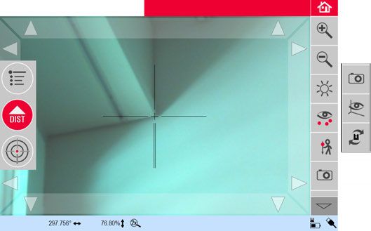
Introduction
Purchase Congratulations on the purchase of the Leica 3D Disto.
This manual contains important safety directions as well as instructions for setting up
the product and operating it. Refer to "1 Safety Directions" for further information.
Read carefully through the User Manual before you switch on the product.
Product Identifica- The model and serial number of your product are indicated on the type plate.
tion Always refer to this information when you need to contact your agency or Leica
Geosystems authorised service centre.
Trademarks • Windows is a registered trademark of Microsoft Corporation in the United States
and other countries
All other trademarks are the property of their respective owners.
Available
Name Description/Format
Documentation
3D Disto Quick Intended as quick reference guide for first setup.
Start
3D Disto User All instructions required in order to operate the instru- -
Manual ment at a basic level are contained in this User Manual.
Provides an overview of the instrument together with
technical data and safety directions.
Safety Manual Provides important safety instructions for use of 3D
Disto.
Refer to the following resources for all 3D Disto documentation/software:
• Leica USB memory stick
• https://myworld.leica-geosystems.com
Leica Geosystems On the last page of this manual, you can find the address of Leica Geosystems head-
Address Book quarters. For a list of regional contacts, please visit
http://leica-geosystems.com/contact-us/sales_support.
3D Disto, Introduction 2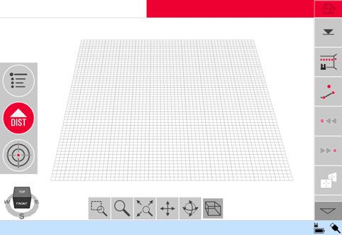
myWorld@Leica Geosystems (https://myworld.leica-geosystems.com) offers a
                     wide range of services, information and training material.
                     With direct access to myWorld, you are able to access all relevant services whenever
                     it is convenient for you, 24 hours a day, 7 days per week. This increases your efficiency
                     and keeps you and your equipment instantly updated with the latest information from
                     Leica Geosystems.
                         Service         Description
                         myProducts      Add all products that you and your company own and explore your
                                         world of Leica Geosystems: View detailed information on your prod-
                                         ucts and update your products with the latest software and keep up-
                                         to-date with the latest documentation.
                         myService       View the current service status and full service history of your prod-
                                         ucts in Leica Geosystems service centres. Access detailed informa-
                                         tion on the services performed and download your latest calibration
                                         certificates and service reports.
                         mySupport       View the current service status and full service history of your prod-
                                         ucts in Leica Geosystems service centres. Access detailed informa-
                                         tion on the services performed and download your latest calibration
                                         certificates and service reports.
                         myTraining      Enhance your product knowledge with Leica Geosystems Campus -
                                         Information, Knowledge, Training. Study the latest online training
                                         material on your products and register for seminars or courses in
                                         your country.
                         myTrustedSer- Add your subscriptions and manage users for Leica Geosystems
                         vices         Trusted Services, the secure software services, that assist you to
                                       optimise your workflow and increase your efficiency.

3D Disto, Introduction                                                                                        3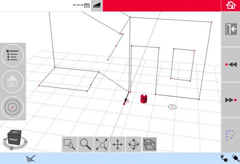
Table of Contents
In this manual       Chapter                                                             Page

                     1        Safety   Directions                                          6
                              1.1       General Introduction                               6
                              1.2       Definition of Use                                  7
                              1.3       Limits of Use                                      7
                              1.4       Responsibilities                                   7
                              1.5       Hazards of Use                                     8
                              1.6       Laser Classification                               9
                                        1.6.1     General                                  9
                                        1.6.2     Integrated Distance Meter               10
                              1.7       Electromagnetic Compatibility EMC                 10
                              1.8       Conformity to National Regulations                12
                                        1.8.1     FCC Statement, Applicable in U.S.       12
                                        1.8.2     ISED Statement, Applicable in Canada    12
                                        1.8.3     Japanese Radio Law Compliance           12
                                        1.8.4     Singapore                               13
                              1.9       Labelling                                         13
                     2        Description of the System                                   14
                              2.1     Overview                                            14
                              2.2     Container Contents                                  14
                              2.3     Instrument Components                               15
                                      2.3.1    3D Disto                                   15
                                      2.3.2    RM100 Remote Control                       17
                              2.4     Power Supply                                        18
                              2.5     3D Disto Software                                   19
                                      2.5.1    Software Concept                           19
                                      2.5.2    User Interface                             20
                     3        Instrument Setup                                            24
                              3.1     Setting Up 3D Disto                                 24
                              3.2     Connecting the 3D Disto to a Windows Device         24
                              3.3     Assistant                                           25
                              3.4     Tilt Sensor                                         26
                              3.5     Device Configuration and Menu Settings              26
                              3.6     Data Management                                     28
                                      3.6.1     File Manager                              28
                                      3.6.2     Export and Import of Data                 29
                              3.7     Calculator                                          30
                     4        Technical Terms and Abbreviations                           31
                     5        Operation                                                   34
                              5.1     Measurements                                        34
                              5.2     Pointfinder                                         34
                              5.3     Measurement Workflow                                36

3D Disto, Table of Contents                                                                4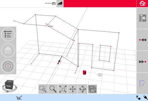
6        Software Applications                                             39
                              6.1    Overview                                                   39
                              6.2    Measure                                                    39
                                     6.2.1     Reference Height                                 39
                                     6.2.2     Scan Tool for Automated Scans                    40
                                     6.2.3     CAD Tools                                        43
                              6.3    Projector                                                  51
                                     6.3.1     Workflow                                         51
                                     6.3.2     Targeting and Layout with RM100 Remote Control   54
                              6.4    Location                                                   54
                              6.5    Tool Kit                                                   57
                                     6.5.1     Comfort Plumbing                                 57
                                     6.5.2     Comfort Targeting                                58
                                     6.5.3     Comfort Level                                    59
                                     6.5.4     Meter Mark                                       59
                                     6.5.5     Height Tracking                                  60
                                     6.5.6     Parallel Line                                    61
                     7        Error Messages                                                    62
                     8        Check & Adjust                                                    63
                              8.1    Overview                                                   63
                              8.2    Tilt Sensor Calibration                                    63
                              8.3    Crosshairs Offset                                          64
                              8.4    V-Index Error                                              64
                              8.5    Reset to Factory Settings                                  65
                     9        Instrument Protection (Theft Protection)                          66
                     10       Care and Transport                                                67
                              10.1    Transport                                                 67
                              10.2    Storage                                                   67
                              10.3    Cleaning and Drying                                       68
                     11       Technical Data                                                    69
                              11.1    Technical Data                                            69
                              11.2    Conformity to National Regulations                        70
                              11.3    Dangerous Goods Regulations                               71
                     12       Warranty under PROTECT by Leica Geosystems                        72
                     13       Software Licence Agreement                                        73

3D Disto, Table of Contents                                                                      5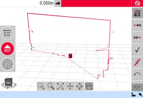
1 Safety Directions
1.1 General Introduction
Description The following directions enable the person responsible for the product, and the
person who actually uses the equipment, to anticipate and avoid operational hazards.
The person responsible for the product must ensure that all users understand these
directions and adhere to them.
About Warning Warning messages are an essential part of the safety concept of the instrument. They
Messages appear wherever hazards or hazardous situations can occur.
Warning messages...
• make the user alert about direct and indirect hazards concerning the use of the
product.
• contain general rules of behaviour.
For the users‘ safety, all safety instructions and safety messages shall be strictly
observed and followed! Therefore, the manual must always be available to all persons
performing any tasks described here.
DANGER, WARNING, CAUTION and NOTICE are standardised signal words for iden-
tifying levels of hazards and risks related to personal injury and property damage. For
your safety, it is important to read and fully understand the following table with the
different signal words and their definitions! Supplementary safety information
symbols may be placed within a warning message as well as supplementary text.
Type Description
DANGER Indicates an imminently hazardous situation which, if not
avoided, will result in death or serious injury.
WARNING Indicates a potentially hazardous situation or an unintended
use which, if not avoided, could result in death or serious injury.
CAUTION Indicates a potentially hazardous situation or an unintended
use which, if not avoided, may result in minor or moderate
injury.
Indicates a potentially hazardous situation or an unintended
NOTICE
use which, if not avoided, may result in appreciable material,
financial and environmental damage.
Important paragraphs which must be adhered to in practice as
they enable the product to be used in a technically correct and
efficient manner.
3D Disto, Safety Directions 6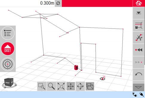
1.2 Definition of Use
Intended Use • 3D measuring of distances, heights, grades, angles, area and volume.
• Manual and automatic measurement of room dimensions.
• Automatic measurement of profiles.
• Laying out points and designs, for example from blueprint.
• Generation of drawings.
• Camera functionality.
• Import/Export of data.
• Administration of data.
Reasonably fore- • Use of the product without instruction.
seeable misuse • Use outside of the intended use and limits.
• Disabling safety systems.
• Removal of hazard notices.
• Opening the product using tools, for example screwdriver, unless this is permitted
for certain functions.
• Modification or conversion of the product.
• Use after misappropriation.
• Use of products with recognizable damages or defects.
• Use with accessories from other manufacturers without the prior explicit approval
of Leica Geosystems.
• Inadequate safeguards at the working site.
• Deliberate dazzling of third parties.
• Controlling of machines, moving objects or similar monitoring application without
additional control and safety installations.
1.3 Limits of Use
Environment Suitable for use in an atmosphere appropriate for permanent human habitation: not
suitable for use in aggressive or explosive environments.
DANGER Local safety authorities and safety experts must be contacted before working in
hazardous areas, or close to electrical installations or similar situations by the person
in charge of the product.
1.4 Responsibilities
Manufacturer of Leica Geosystems AG, CH-9435 Heerbrugg, hereinafter referred to as Leica Geosys-
the product tems, is responsible for supplying the product, including the user manual and original
accessories, in a safe condition.
Person responsible The person responsible for the product has the following duties:
for the product • To understand the safety instructions on the product and the instructions in the
user manual.
• To ensure that it is used in accordance with the instructions.
• To be familiar with local regulations relating to safety and accident prevention.
• To inform Leica Geosystems immediately if the product and the application
becomes unsafe.
• To ensure that the national laws, regulations and conditions for the operation of
the product are respected.
3D Disto, Safety Directions 7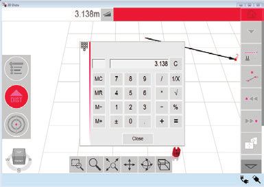
1.5 Hazards of Use
CAUTION Watch out for erroneous measurement results if the product has been dropped or has
been misused, modified, stored for long periods or transported.
Precautions:
Periodically carry out test measurements, particularly after the product has been
subjected to abnormal use and before and after important measurements.
WARNING During dynamic applications, for example stakeout procedures there is a danger of
accidents occurring if the user does not pay attention to the environmental conditions
around, for example obstacles, excavations or traffic.
Precautions:
The person responsible for the product must make all users fully aware of the existing
dangers.
WARNING Inadequate securing of the working site can lead to dangerous situations, for example
in traffic, on building sites and at industrial installations.
Precautions:
Always ensure that the working site is adequately secured. Adhere to the regulations
governing safety, accident prevention and road traffic.
CAUTION If the accessories used with the product are not properly secured and the product is
subjected to mechanical shock, for example blows or falling, the product may be
damaged or people can sustain injury.
Precautions:
When setting up the product, make sure that the accessories are correctly adapted,
fitted, secured, and locked in position.
Avoid subjecting the product to mechanical stress.
CAUTION During the transport, shipping or disposal of batteries it is possible for inappropriate
mechanical influences to constitute a fire hazard.
Precautions:
Before shipping the product or disposing of it, discharge the batteries by running the
product until they are flat.
When transporting or shipping batteries, the person in charge of the product must
ensure that the applicable national and international rules and regulations are
observed. Before transportation or shipping contact your local passenger or freight
transport company.
WARNING High mechanical stress, high ambient temperatures or immersion into fluids can cause
leakage, fire or explosions of the batteries.
Precautions:
Protect the batteries from mechanical influences and high ambient temperatures. Do
not drop or immerse batteries into fluids.
WARNING If battery terminals are short circuited e.g. by coming in contact with jewellery, keys,
metallised paper or other metals, the battery can overheat and cause injury or fire, for
example by storing or transporting in pockets.
Precautions:
Make sure that the battery terminals do not come into contact with metallic objects.
3D Disto, Safety Directions 8
WARNING If the product is improperly disposed of, the following can happen:
• If polymer parts are burnt, poisonous gases are produced which may impair health.
• If batteries are damaged or are heated strongly, they can explode and cause
poisoning, burning, corrosion or environmental contamination.
• By disposing of the product irresponsibly you may enable unauthorised persons to
use it in contravention of the regulations, exposing themselves and third parties to
the risk of severe injury and rendering the environment liable to contamination.
Precautions:
The product must not be disposed with household waste.
Dispose of the product appropriately in accordance with the national
regulations in force in your country.
Always prevent access to the product by unauthorised personnel.
Product-specific treatment and waste management information can be received from
your Leica Geosystems distributor.
WARNING Changes or modifications not expressly approved by Leica Geosystems for compliance
could void the user's authority to operate the equipment.
WARNING Only Leica Geosystems authorised service centres are entitled to repair these prod-
ucts.
1.6 Laser Classification
1.6.1 General
General The following chapters provide instructions and training information about laser safety
according to international standard IEC 60825-1 (2014-05) and technical report
IEC TR 60825-14 (2004-02). The information enables the person responsible for the
product and the person who actually uses the equipment, to anticipate and avoid
operational hazards.
According to IEC TR 60825-14 (2004-02), products classified as laser class 1,
class 2 and class 3R do not require:
• laser safety officer involvement,
• protective clothes and eyewear,
• special warning signs in the laser working area
if used and operated as defined in this User Manual due to the low eye hazard
level.
National laws and local regulations could impose more stringent instructions
for the safe use of lasers than IEC 60825-1 (2014-05) and IEC TR 60825-14
(2004-02).
3D Disto, Safety Directions 9
1.6.2                 Integrated Distance Meter

Integrated Distance   The Leica 3D Disto produces a visible laser beam which emerges from the front of the
Meter                 instrument.

                      The laser product described in this section is classified as laser class 2 in accordance
                      with:
                      • IEC 60825-1 (2014-05): “Safety of laser products”

                      These products are safe for momentary exposures but can be hazardous for deliberate
                      staring into the beam. The beam may cause dazzle, flash-blindness and after-images,
                      particularly under low ambient light conditions.

                      Description                                     Value
                      Wavelength                                      620 nm - 690 nm
Maximum average radiant power CAUTION Disturbances caused by electromagnetic radiation can result in erroneous measure-
ments.
Although the product meets the strict regulations and standards which are in force in
this respect, Leica Geosystems cannot completely exclude the possibility that the
product may be disturbed by intense electromagnetic radiation, for example, near
radio transmitters, two-way radios or diesel generators.
Precautions:
Check the plausibility of results obtained under these conditions.
CAUTION If the product is operated with connecting cables attached at only one of their two
ends, for example external supply cables, interface cables, the permitted level of elec-
tromagnetic radiation may be exceeded and the correct functioning of other products
may be impaired.
Precautions:
While the product is in use, connecting cables, for example product to external battery,
product to computer, must be connected at both ends.
Radios or Digital Use of product with radio or digital cellular phone devices:
Cellular Phones
WARNING Electromagnetic fields can cause disturbances in other equipment, in installations, in
medical devices, for example pacemakers or hearing aids and in aircraft. It can also
affect humans and animals.
Precautions:
Although the product meets the strict regulations and standards which are in force in
this respect, Leica Geosystems cannot completely exclude the possibility that other
equipment can be disturbed or that humans or animals can be affected.
• Do not operate the product with radio or digital cellular phone devices in the vicinity
of filling stations or chemical installations, or in other areas where an explosion
hazard exists.
• Do not operate the product with radio or digital cellular phone devices near to
medical equipment.
• Do not operate the product with radio or digital cellular phone devices in aircraft.
3D Disto, Safety Directions 111.8 Conformity to National Regulations
1.8.1 FCC Statement, Applicable in U.S.
WARNING This equipment has been tested and found to comply with the limits for a Class B
digital device, pursuant to part 15 of the FCC rules.
These limits are designed to provide reasonable protection against harmful interfer-
ence in a residential installation.
This equipment generates, uses and can radiate radio frequency energy and, if not
installed and used in accordance with the instructions, may cause harmful interference
to radio communications. However, there is no guarantee that interference will not
occur in a particular installation.
If this equipment does cause harmful interference to radio or television reception,
which can be determined by turning the equipment off and on, the user is encouraged
to try to correct the interference by one or more of the following measures:
• Reorient or relocate the receiving antenna.
• Increase the separation between the equipment and the receiver.
• Connect the equipment into an outlet on a circuit different from that to which the
receiver is connected.
• Consult the dealer or an experienced radio/TV technician for help.
This device complies with part 15 of the FCC Rules. Operation is subject to the
following two conditions:
1) This device may not cause harmful interference, and
2) This device must accept any interference received, including interference that may
cause undesired operation.
FCC Radiation Expo- The radiated output power of the instrument is far below the FCC radio frequency
sure Statement exposure limits. Nevertheless, the instrument should be used in such a manner that
the potential for human contact during normal operation is minimised. To avoid the
possibility of exceeding the FCC radio frequency exposure limits, keep a distance of at
least 20 cm between you (or any other person in the vicinity) and theantenna that is
built into the instrument.
1.8.2 ISED Statement, Applicable in Canada
WARNING This device complies with Industry Canada’s licence-exempt RSSs. Operation is subject
to the following two conditions:
1) This device may not cause interference; and
2) This device must accept any interference, including interference that may cause
undesired operation of the device.
Radio Frequency The radiated RF output power of the instrument is below the Health Canada’s Safety
(RF) Exposure Code 6 exclusion limit for portable devices (radiated element separation distance
Compliance State- between the radiating element and user and/or bystander is below 20 cm).
ment
1.8.3 Japanese Radio Law Compliance
Japanese Radio Law Compliance:
• This device is granted pursuant to the Japanese Radio Law (電波法 ).
• This device should not be modified (otherwise the granted designation number will
become invalid).
3D Disto, Safety Directions 121.8.4 Singapore
Leica 3D Disto:
Complies with
IMDA Standards
DB102875
1.9 Labelling
Labelling 3D Disto
010747_002
Labelling RM100
Type: RM100
Remote Control Art.No.: 780994
Power: 1.5V / 0.4A
Leica Geosystems AG
CH-9435 Heerbrugg
Made in XXX
100
RM
010748_001
3D Disto, Safety Directions 132 Description of the System
2.1 Overview
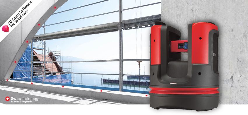
3D Disto General The Leica 3D Disto is a three-dimensional measuring and projection system. To
Description operate the 3D Disto you need a Windows device. To perform certain functions you
can also use the RM100 Remote Control.
a) 3D Disto
b) USB Cable
c) Windows device
(not part of the
delivery)
d) RM100 Remote
010714_001 a b c d Control
2.2 Container Contents
Container Contents a b c
(1/2)
010992_002 d e f
a) 3D Disto with built-in SD WLAN card
b) USB connection cable 3D Disto to the Windows device
c) Safety Instructions Manual, 3D Disto Quick Start, CE and Producer Certificate,
USB memory stick (with licence keys, User Manual, Windows software and setup
information)
d) Four country-specific cables for 3D Disto power supply
e) Target marks, self-adhesive, 50 units in one bag
f) RM100 remote control and battery
3D Disto, Description of the System 14Container Contents
(2/2)
a
b
010993_001
a) Ruler for offset points
b) 3D Disto power supply
2.3 Instrument Components
2.3.1 3D Disto
Motor-driven Part d
a c
e
b
c
c
f
a) LEDs for 3D Disto status
b) ON/OFF button
c) Grips to hold the instrument
d) Infrared (IR) interface
g
e) WLAN interface
f) Laser distance meter with Point-
finder
010735_001 g) Circular bubble
Battery Socket
a) Tripod thread 5/8”
b) 90° marking
c) Power supply connector for 3D Disto
a b c d e b d) LED for battery status
010736_001 e) Data cable connector
3D Disto, Description of the System 15LEDs and Buttons
Button/LEDs Description
ON/OFF button Button to turn instrument ON or OFF.
Instrument turns OFF after 15 minutes if not connected
to the PC.
010732_001
LEDs for 3D Disto status • Green and orange LEDs light up continuously: 3D Disto
is booting.
• Orange LED flashes: Self-levelling procedure is running
010731_001
or tilt > 3°.
• Green LED flashes: 3D Disto is ready for measurement.
Tilt sensor is on.
• Orange LED lights up continuously: An error occurred.
Refer to "7 Error Messages".
• Green and orange LEDs light up continuously: Press the
ON button to reset the instrument.
For experts only: Tilt sensor off
Green LED flashes once; orange LED three times.
LED for battery status If instrument is on and connected to the charger:
• Green LED flashes 1x: Battery is charged to 25%.
• Green LED flashes 2x: Battery is charged to 50%.
010733_001
• Green LED flashes 3x: Battery is charged to 75%.
• Green LED is on: Battery is fully charged.
LDM Laser
Status of Laser Beam Description
OFF Pointfinder is OFF or 3D Disto targets automatically.
ON Pointfinder is ON or user is targeting by Remote Control.
010734_001 Flashing To indicate the precise position of a projected point.
3D Disto, Description of the System 162.3.2 RM100 Remote Control
Remote Control a b c d e
Components
a) Key ring
b) Battery compartment
c) DIST button
d) Navigation buttons:
100
RM Up/Down/Right/Left
010737_001 e) Control LED
Navigation Buttons The RM100 Remote Control has five buttons that allow turning the 3D Disto and
executing a distance measurement or point projection, depending on the application
program running.
The RM100 Remote Control does not support the Tool Kit applications.
Targeting Procedure
1) Rough targeting: hold / / / to turn the 3D Disto as long as key is
pressed.
2) Fine targeting: short tap on / / / to turn the 3D Disto by small single
steps.
3) Measure: Press .
3D Disto, Description of the System 172.4 Power Supply
First-time Use / • The battery must be charged prior to using it for the first time because it is deliv-
Charging Batteries ered with an energy content as low as possible.
• The permissible temperature range for charging is between 0°C to +40°C/ +32°F to
+104°F. For optimal charging, we recommend charging the batteries at a low
ambient temperature of +10°C to +20°C/+50°F to +68°F if possible.
• It is normal for the battery to become warm during charging. Using the chargers
recommended by Leica Geosystems, it is not possible to charge the battery if the
temperature is too high.
• For new batteries or batteries that have been stored for a long time (> three
months), it is effectual to make only one charge/discharge cycle.
• For Li-Ion batteries, a single discharging and charging cycle is sufficient. We recom-
mend carrying out the process when the battery capacity indicated on the charger
or on a Leica Geosystems product deviates significantly from the actual battery
capacity available.
Operation / • Batteries can operate from -10°C to +50°C/14°F to +122°F.
Discharging • Low operating temperatures reduce the capacity that can be drawn; high operating
temperatures reduce the service life of the battery.
3D Disto Power
Supply Only Leica Geosystems authorised service workshops are entitled to replace
the battery socket.
• Internal: by battery socket, with non-removable Li-Ion batteries, 14.4 V, 63 Wh.
• External: Power supply for 3D Disto connected by cable with country-specific plugs
for worldwide use.
Input: 100 - 240 V AC, 50/60 Hz.
Output: 24 V DC, 2.5 A.
Length: 1.80 m.
a
a) Battery socket
010761_001
b b) Power supply connector
RM100 Remote The RM100 is equipped with one AA alkaline battery, 1.5 V.
Control Power 1) Push the battery cover in the
Supply direction of the arrow to open
the battery compartment.
2) Replace the battery and refit
2 the battery cover.
1
010762_001
3D Disto, Description of the System 182.5 3D Disto Software
2.5.1 Software Concept
3D Disto System The 3D Disto includes a user interface software for computers with Windows oper-
Software ating systems.
Hardware requirements:
• Windows 7 and later. RT versions are not supported.
• Desktop devices or laptops with keyboard and mouse.
• Touchscreen devices and tablets.
• Screen resolution at least 680 x 1000 px
• 32 bit or 64 bit
Insert the Leica USB memory stick only into a USB port “Type A”. For other port
types, use an adapter. Ensure, that both the port and the adapter have “on-
the-go” functionality (OTG).
License Key To enable the 3D Disto applications, the software needs a licence key. Refer to the
following list for information about where to find the licence keys:
• On the delivery papers or receipt from your dealer.
• On the USB memory stick (key file).
• On the Leica myWorld website after registering your product.
Activating Soft- Entering the License Key Manually
ware Applications
with the License Connect the 3D Disto to your Windows
device and start the 3D Disto software
Key application.
1) On the main screen, press the Menu button.
2) Select Device... » Software... » License...
» Enter license keys.
3) Enter the license key and press OK.
Importing the License Key
1) Click on the 3D Disto Data icon on your desktop.
2) Copy the license key file into the folder “license”.
Customised Appli- Customised software, specific to user requirements, can be developed using the third-
cation Programs party software development environment. For further information, contact a Leica
Geosystems representative.
Software Update 1) Start your internet browser and go to the myWorld homepage.
(https://myworld.leica-geosystems.com)
2) Register your product by entering the equipment number.
3) Choose the myProducts page, choose the latest software version and press the
Download key.
3D Disto, Description of the System 192.5.2 User Interface
Home Screen
All shown screens are examples. It is possible that local software versions vary
from the standard version.
a
b
c a) Result window with result
choice key
b) Title bar with Home key
d
c) Toolbar
e d) Sketch area/Pointfinder
f e) Main operation bar
f) 3D Disto position
g g) Status bar
010764_002 h h) Navigation cube and tools
Element Description
Title bar Shows the running application.
save and close files or running applications.
Main operation bar Contains the following buttons:
• Menu
Opens the menu to start applications or to define
settings.
• DIST button
Starts measurement or layout of points.
• Pointfinder
Opens, closes and locks Pointfinder.
These keys are displayed during all applications.
Sketch area Displays measured points, lines and areas and correct
position of 3D Disto in relation to measured points -
either in foot print or unfold mode/face mode.
Pointfinder Shows 3D Disto live video stream used to target points
and to take pictures.
Results window Displays all results such as distances, heights, slopes,
areas, angles together with the corresponding result
choice key, for example . Tapping on the results opens
the calculator.
Toolbar Contains application-specific tool keys. Refer to " Toolbar
of the Standard Application (Measure)".
Status bar Displays status of connections, batteries, running func-
tion mode and assistant support.
Navigation cube and tools Changes perspective and scale of the sketch. Click on a
face, a corner or an edge of the cube for pre-defined
views. Use the navigation tools to adjust the view individ-
ually.
3D Disto, Description of the System 20Operating Principles Selecting or Drawing Items
for the Sketch View
Ensure, that the navigation tools are deactivated.
To select a point or line in the sketch, click with the mouse or tap with one finger.
To draw a line, select a point with mouse, stylus or finger, slide to the desired point
and release.
Adjusting the Sketch View with Navigation Tools
Use the navigation tools to adjust the sketch view individually.
• Zoom by drawing a rectangular area
• Zoom
• Fit the whole model into the view
• Pan the sketch
• Rotate the sketch
• Change the perspective
To activate a navigation tool, click or tap on it. The selected tool is highlighted and the
cursor changes.
To deactivate a tool, click or tap on it again.
Adjusting the Sketch View with the Navigation Cube
You can also use the navigation cube to adjust the sketch view.
Click and drag the cube to adjust the view individually.
Click on a face, a corner or an edge of the cube for pre-defined views.
011137_001
Gestures for Touch-Screen
If your device has a touch screen, you can use two-finger gestures for quickly adjusting
the sketch view without using the navigation tools:
Swipe: Zoom in:
009108_001
011136_001
Rotate: Zoom out:
009111_001
009110_001
3D Disto, Description of the System 21Toolbar of the
Key Description
Standard Applica-
tion (Measure) Enter and measure a reference height.
Start a line or surface scan.
Disable line drawing.
Go one point backward.
Go one point forward.
Display all photos in the sketch.
Display list of CAD tools.
Confirm the current operation.
Start area or volume mode.
Undo or redo last command.
Clear functions.
Status Bar
Icon Description
Indicates remaining battery capacity for the 3D Disto.
Indicates 3D Disto is connected to power supply.
Indicates USB connection between Windows device and 3D Disto.
Indicates WLAN connection is working.
Scale of sketch area and key to change zoom level.
Indicates zoom level/magnification of Pointfinder.
Indicates tilt sensor is turned off.
3D Disto, Description of the System 22Icons in the Result
Icon Description
Window
Horizontal Distance
Tie distance
Height, height difference
Left angle
Right angle
Coordinates: X, Y
Tilt
Horizontal/tilted area
Horizontal/titled area perimeter
Volume height
Volume
Circle size
Circumference
Diameter
Scan area
Scan perimeter
Scan volume
Distance between point and plane.
Perpendicular distance of a point to the reference line.
3D Disto_052
Distance from the reference line base point to the foot of the perpen-
dicular.
3D Disto_053
3D Disto, Description of the System 233 Instrument Setup
3.1 Setting Up 3D Disto
Setup Step-by-Step The following description assumes setup on a tripod. You can also place the 3D Disto
on flat surfaces such as floor or boards.
Step Description
It is always recommended to shield the instrument from direct sunlight and
avoid uneven temperatures around the instrument.
1. Set up the tripod in a suitable place where the 4
points to be measured can be targeted well and 2
extend the tripod legs to a comfortable working 3
height.
2. Place the 3D Disto onto the tripod head.
Tighten the central tripod fixing screw.
3. Centre the circular bubble on the 3D Disto by 1
adjusting the tripod legs. 1 1
4.
Press to turn on the instrument.
3D Disto starts self-levelling: the tilt is checked 010813_001
by a tilt sensor and the instrument levels itself
if the tilt is < 3°.
Do not move the 3D Disto while self-levelling procedure is running.
3.2 Connecting the 3D Disto to a Windows Device
Connect 3D Disto to Starting the Software
a Windows Device
Step-by-Step Step Description
1. To start the software, click the 3D Disto icon on your desktop.
When starting the software for the first time, the following screen is
displayed:
If necessary change the settings.
Press to continue.
3D Disto, Instrument Setup 24Step Description
The following screen opens:
a
b
c
d
010818_002
a) Select the WLAN interface.*
b) List of available WLAN devices and their respective signal intensity. Select
a device to connect.
c) If you prefer a cable connection, plug in the USB cable and click here.
d) In order to continue without connection, click here.
* 3D Disto devices with serial number 175... need an external WLAN USB stick.
3.3 Assistant
Assistant and There is an assistant available that will guide you through all measurement tasks with
supporting icons illustrated pop-ups.
If not needed, it can be deactivated in Menu » Settings » Assistant. If assis-
tant is deactivated there are still supporting icons in the status bar, showing
which application is running and what user action is required.
3D Disto, Instrument Setup 253.4 Tilt Sensor
Tilt Sensor A built-in tilt sensor ensures that measurements relate to true horizon or true plumb
line, defined by gravity. The tilt is checked by a tilt sensor and the instrument levels
itself if the tilt is < 3°.
If 3D Disto cannot be levelled the in the status bar is blinking. Level the 3D
Disto or cancel the levelling procedure.
For advanced users only:
If the tilt sensor is OFF the system does not compensate the tilt of the 3D
Disto. All results that refer to a physically horizontal plane, for example tilt,
height differences, horizontal distances, angles, areas, or volumes, now refer
to the tilted horizon of the laser unit. Only the tie distance between two meas-
ured points is independent of the tilt sensor's setting. It can be useful to
disable the tilt sensor in case of vibrations, for example on construction sites
or in unstable or moving environments such as on boats. Almost all measure-
ments can still be completed and exported data can be “levelled” afterwards
by CAD software.
3.5 Device Configuration and Menu Settings
Device Configura- All settings on the setup screen can also
tion be changed through the menu: Choose
Menu » Device.
• Connect 3D Disto to connect by WLAN, USB cable, or disconnect.
• WLAN channel to switch between different channels if connection does not work.
• Tilt sensor to activate/deactivate the tilt sensor.
Choose ON when working in harsh construction environment with many shocks and
vibrations, apart from that choose ON (sensitive).
• Theft protection to protect instrument with security PIN.
• Calibration to check and adjust. Refer to "8 Check & Adjust" for more information.
• Software to update software, to check software version or to enter/activate the
software license key.
3D Disto, Instrument Setup 26Settings Press Menu » Settings, the following
options appear:
• Snap Radius to define the area around a point/line. This setting offers a list of
points that are very close to each other to simplify their selection.
• Assistant to activate/deactivate the assistant.
• Units to change the unit settings.
• Welcome text to enter for example company name.
• On-screen keyboard to define the display mode for the on-screen keyboard on
your touch-screen devices.
Automatic: The on-screen keyboard is displayed automatically as soon as you are
prompted to enter characters.
• Date and time to change date and time settings.
• Language to choose your preferred software language.
• Import/Export settings to change format, coordinates and list separator.
• The instrument has a Reset function. If you select the menu function Reset to
default and confirm, the device returns to the factory settings.
All measurement data is kept.
3D Disto, Instrument Setup 273.6 Data Management
3.6.1 File Manager
File Manager The File Manager handles the entire data administration measurement files, photos
Secure Points and data transfer.
To access the File Manager, press the Menu key and select File Manager.
Description of keys:
Icon Description
Project folder
Folder with photos
Folder with Secure Points
Temporary file
Measure file
Projector file
Toolbar Keys within
Key Function
File Manager
Close folder/File Manager
Go to higher folder level or close File Manager
Create a folder and enter a folder name
Open a selected file or folder
View the selected element.
Data export. Refer to "3.6.2 Export and Import of Data".
Rename file or folder
3D Disto, Instrument Setup 28Key Function
Clear a selected file or folder.
Photo and Secure Photos and Secure Points are stored in separate folders.
Points Administra-
tion
3.6.2 Export and Import of Data
Data Export
Step Description
Step-by-Step
Export applies the distance unit setting to exported coordinates. This setting
can be modified any time before an export is executed.
The import/export settings in the menu allow to set the coordinates of the
first measured point of each application. This setting must be done before
the first point in a new project (e. g. a new scan) is measured; the setting
does not apply retrospectively.
1. Open File Manager, choose a folder or file and press .
A key press on generates a package of export files:
• DXF and DWG files: 2D, 3D
• CSV file: editable, common tabular data format
• TXT file: all results in editable ASCII format. Same content like CSV file
• JPG files of photos and Secure Points.
2. Export data is transferred to the Export folder in the directory My Docu-
ments\Leica Geosystems\3D Disto on your PC.
Data Import
Step Description
Step-by-Step
It is possible to import DXF files or table formats for some applications.
Data should be prepared on the PC before importing. Only points are
imported, no lines. Remove irrelevant data such as frames, logos, coordi-
nates, or orientation arrows in the DXF files before importing them.
1. To access the Import folder, click on the 3D Disto Data icon on your desktop.
2. Copy the CSV or DXF files to the Import folder.
3. Refer to "6.3 Projector" for more information.
3D Disto, Instrument Setup 293.7 Calculator
Using calculator • Tap on the result in the result window to start the calculator.
• Another option is to press Menu » Calculator.
010862_002
Memory Function
The memory function allows you to add or subtract results, e.g. areas or volumes.
• Click MC to clear memory.
• Click MR to retrieve a value stored in memory.
• Click M- to subtract the displayed value from the value in memory.
• Click M+ to add the displayed value to the value in memory.
To save a certain value to the memory: Click MC to clear memory, enter value
and press M+. To save the value as negative value, press M-.
3D Disto, Instrument Setup 304 Technical Terms and Abbreviations
Horizontal Angle
a
010863_001 a) Horizontal angle: [°] or [gon]
Vertical Angle Setting: Horizon = 0
a
010864_001 a) Vertical angle: [°], [gon], [1:n] or [%]
Setting: Horizon = 90°/100 gon
a
010865_001 a) Vertical angle: [°] or [gon]
Distances
a
010867_001 a) Perpendicular distance
a
b
c
a) Tie distance
b) Vertical distance = height difference
010868_001 c) Horizontal distance
3D Disto, Technical Terms and Abbreviations 31Areas
a
b
a) Tilted area, as measured
010869_001 b) Horizontal area, calculated by 3D Disto
References +3.00
+2.10
0.00 a
-0.02 0.00
a) Reference height:
010870_001
0.00
A level that all heights refer to.
1
10
3.
1
91
2. 0
04 2
7. 00
7.
a) Reference axis/line:
010871_001 a A line that all dimensions refer to.
Tilt Sensor The tilt sensor guarantees correct results even if the 3D Disto is not set up horizon-
tally.
0-3°
010876_001 010877_001
Tilt sensor off = disabled Tilt sensor on = enabled
All measurement results relate to the tilted All measurement results relate to the
axis and horizon of the 3D Disto. horizontal axis and horizon if the 3D
Disto is set up between 0° and 3°.
Secure Points Secure Points link measurements to a coordinate system. These reference points
allow changing the 3D Disto location or continuing measurements at a later time, so
that all measurements fit together perfectly.
010873_001
Refer to "6.4 Location" for more information.
3D Disto, Technical Terms and Abbreviations 32Layout or Projection Design data in DXF and common table formats can be imported and used to lay out
the corresponding points or grids.
CAD
010874_001
Laser Distance The laser distance meter (LDM) determines distances using a visible red laser beam.
Meter
Calibration Calibration is a workflow to check and adjust the accuracy of the instrument. Refer to
"8 Check & Adjust" for more information.
Ruler for offset The ruler for offset points is an accessory to measure inaccessible or hidden points.
points
? a
010875_001
a) Ruler for offset points
3D Disto, Technical Terms and Abbreviations 335 Operation
5.1 Measurements
Description The 3D Disto is a combination of a precise laser distance meter (LDM) and angle
encoders. Measurements are used to establish the relation between different targets,
such as horizontal distances, tie distances, height differences to determine room
dimensions, angles from wall to wall, areas, volumes, plumb points, or other features.
5.2 Pointfinder
Description The 3D Disto has an integrated camera. It is accessible by and it shows the camera
image directly on the 3D Disto display. The crosshairs in the Pointfinder image allow
precise targeting and measuring even if the laser beam is not visible, for example over
long distances or because of bright backlight conditions.
Example of a Pointfinder screen:
Using Pointfinder Pointfinder Key
To start the Pointfinder, press .
A second key press activates the lock mode, a third one unlock and closes Pointfinder.
A lock symbol on a key indicates the lock mode.
Targeting: There are different options to target a measurement point:
a a) Press the arrow keys on the screen for targeting, hold for
fast 3D Disto turns and short taps for single step turns.
b) Tap & Measure Targeting: tap on a position on the
screen. Laser point turns to this point automatically.
b c) Joystick Targeting: is activated by long tap on the centre
of the crosshairs. A red dot appears in the centre. Slide
stylus on the screen to turn 3D Disto in this direction in
real-time until red arrow is released. The longer the red
arrow is, the faster the 3D Disto turns.
c
011126_001
3D Disto, Operation 34Toolbar description
Key Function
Press to zoom in or out.
Press to adjust the brightness of the camera.
Press to display/hide all measured points.
Press to measure hidden points.
Select an offset tool in the pop-up:
• Vertical offset: Measure one point on any vertical target.
• Individual offset: Measure two points on a pole or other hardware.
• Offset ruler: Measure two points on the 3D Disto offset point ruler.
An assistant leads through the workflow.
Press to take pictures for documentation purposes.
Press in dark conditions to change Pointfinder picture to edge mode.
Edges and corners will be highlighted in black.
Press to choose between different turn commands:
• Turn 90° right
• Turn 90° left
• Turn ?°: Enter the horizontal angle by which the 3D Disto should
turn.
• Horizon: 3D Disto goes to 0% slope in horizontal position.
• Plumb up: This option can be used to plumb up a point by setting
up the 3D Disto exactly over it. Use the 90° markings on the 3D
Disto socket for centring.
3D Disto, Operation 355.3 Measurement Workflow
Measurements
Step Description
step-by-step
1.
To target the first point, for example a corner, press and use the arrow
keys or another method as described in "5.2 Pointfinder", to move the laser
point to the desired position.
While targeting, ensure the laser beam is not split along corners or edges.
011133_001
2.
Press to measure.
3. Target the second point as described in the previous steps.
A line is displayed from the first to the second measured point.
4. Proceed as described for measuring further points or use to close/finish
the polygon.
3D Disto, Operation 36Step Description
In special situations the proposed line is not available. Polygons can also be
closed and results created by drawing a line with the stylus between the two
points to be connected.
To change the view to a suitable perspective, use the navigation tools or click
on the navigation cube.
5. Press to choose between save, save as, clear screen, close measure-
ments without saving.
3D Disto, Operation 37Areas & Volume The 3D Disto can also help determine areas and volumes. Both can be determined
Calculations during or after measuring.
Step Description
1. Press .
2. Select line to be added to area and press .
3.
Proceed that way for all lines and press .
4. Pop-up appears to choose between the different options to define the
height:
• Enter height:
Enter a desired value and press OK.
• Measure height:
Pointfinder opens, target and measure a point on floor with , followed
by point on ceiling. You can measure the points anywhere on the floor or
ceiling area. The height appears in the results window.
• Close list:
The result is an area.
5. To change the height or to calculate the volume with a selected area press
and proceed as described in the previous steps.
6. Quit application by pressing .
3D Disto, Operation 386 Software Applications
6.1 Overview
Description There are a variety of software application programs available addressing a wide spec-
trum of construction tasks and facilitating daily work.
• Measure:
Provides practical features to measure room dimension, walls, windows, stairs and
other details with reference height, manually or automatically.
• Projector:
Enables layout of grids and other design data on floors, ceiling, or walls.
• Location:
Routine to easily and correctly check and relocate the position of the 3D Disto.
• Tool Kit:
Smart measuring and set-out tools.
6.2 Measure
Description This application program measures room dimensions, including details. For these
measurements several additional features are available:
• Reference Height
• Single point measurement
• Scan tool for automated scans
• CAD tools
6.2.1 Reference Height
Define a Reference Within the measure application, you can define a known height as reference height.
Height All further measured heights will refer to this reference height.
Step-by-Step
Step Description
1.
Press .
2. Pop-up prompts to enter and measure reference height. Enter the value and
press OK.
3. Pointfinder opens.
Target the reference height and press .
4. Reference height is displayed in the sketch area.
3D Disto, Software Applications 396.2.2 Scan Tool for Automated Scans
Description This tool executes automated horizontal, vertical and slope profile measurements and
surface scans.
Ideal for measuring rooms with non-square corners or curved walls, inaccessible
points, slopes or areas.
010918_001
Line Scan, step-by-
Step Description
step
1. Press to start scan.
2. Pop-up offers line scans and surface scans.
Press to select line scans.
3. Pop-up prompts scan types.
• Horizontal
• Vertical
• Slope
4. Pointfinder opens to target and measure start point.
Target and press .
For vertical line scan:
Pop-up prompts to choose scan orientation:
• Perpendicular to wall
• Free: An assistant leads through the workflow.
5. Pop-up prompts to define scan direction.
Horizontal Line Scan:
• Left (360°)
• Point-to point
• Right (360°)
3D Disto, Software Applications 40Step Description
Vertical Line Scan:
• Up (360°)
• Point-to point
• Down (360°)
Slope Scan:
Pointfinder opens.
Target scan end and press .
6. Pop-up window prompts to define spacing of the measurement.
Choose an interval and press OK or go to the rightmost position to enter indi-
vidual intervals.
7.
For best scan results do not choose small intervals at long distances.
Press OK.
Scan starts.
Toolbar changes.
Press to start the camera. Press again to unlock.
Press to change scan spacing, skip the rest of the scan, continue scan, or
cancel scan.
Press to skip a scan point that you do not need or that causes problems.
8. If scan is finished pop-up prompts Ready. Edit Scan? Yes/No.
9. If Yes: New Toolbar appears, e.g. to measure missing points with DIST or
delete unneeded points with Trash key Symbol.
Press or to select points.
Press to start a scan simplification that automatically clears aligned
points.
Press to finish the scan.
3D Disto, Software Applications 41Step Description
10. Press to save and close measurement file.
Surface scan, step-
Step Description
by-step
1. Press to start scan.
2. Pop-up offers line scans and surface scans.
Press for surface scan.
3. Pop-up offers three scan options: horizontal, slope and vertical:
Select your preference according to the surface you want to scan.
Use vertical or horizontal scan to measure on walls, floor and ceiling.
Slope scan is ideal to check the flatness of any surface, independent of its
inclination.
4. Select “precise” or “speedy” option. “Precise” finds the exact position of each
scan point. “Speedy” prioritises short measuring time and robustness. Meas-
urement accuracy is equal.
5. The Pointfinder opens for measurements to define the scan area:
Define the Scan Area:
• horizontal & vertical: measure 2 edges (3 points). The area is completed
automatically
• slope scan: measure the borders of the scan and press to continue.
6. Pop-up window prompts to define spacing of the measurement.
Choose an interval and press OK or go to the rightmost position to enter indi-
vidual intervals.
For best scan results do not choose small intervals at long distances.
3D Disto, Software Applications 42Step Description
7. Press OK.
Scan starts.
The deviation of each scanned point to the reference plane is displayedin the
result window.
For geometric reasons, scan volume computation is an approximation.
Toolbar changes.
Press to start the camera. Press again to unlock.
Press to change scan spacing, skip the rest of the scan, continue scan, or
cancel scan.
Press to skip a scan point that you do not need or that causes problems.
8. Press to save and close measurement file.
6.2.3 CAD Tools
Description CAD tools is a set of drawing functions.
Click the button in the toolbar to display the CAD tools.
The following tools are available:
• Circle
• Rectangle
• Line Intersection
• Line Extension
• Point Shift
• Perpendicular Intersection
3D Disto, Software Applications 43Circle Tool The circle tool’s purpose is mainly to draw a circle on points like sockets or holes.
Step Description
1. Target and measure a point and activate circle function by a long tap on the
point in the sketch area.
2. Select Circle.
3. Pop-up opens.
Enter the value and press OK.
4. Circle is drawn around the chosen point. The results window contains radius,
circumference and size of the circle.
To clear the circle, enter 0 as value for the diameter or press .
3D Disto, Software Applications 44Rectangle Tool
Step Description
1. Measure first and second point of the diagonal of a rectangle, for example a
window, and activate the CAD tool by long tap on the line.
2. The CAD tools menu opens. Select Rectangle.
3. Diagonal changes to a levelled rectangle.
3D Disto, Software Applications 45Line Intersection The Line Intersection tool finds the intersection point between two lines.
Tool
Step Description
Intersection location is computed two-dimensionally in the X-Y plane. Inter-
section point height is computed by extrapolation of the first line.
1. Target and measure two points or select an existing line.
2. Activate CAD tools by a long tap on the line in the sketch area. Select Line
Intersection.
3. The assistant prompts for selecting a second line.
Select a second line.
The intersection point is proposed once a line is chosen:
4. After was pressed, the intersection point is generated and the
connecting lines to the existing points are added.
5.
3D Disto, Software Applications 46Line Extension Tool The Line Extension tool expands a line by a manually entered distance value.
Step Description
Line Extension end-point is computed as the 3-dimensional extrapolation of
the selected line.
1. Target and measure two points or select an existing line.
2. Activate the CAD tools by a long tap on the line in the sketch are. Select Line
Extension.
3. The pop-up prompts for the extension length.
Enter a value and press Ok.
4. The Line Extension end-point is proposed:
5. After was pressed, the new point is generated and the connecting line to
the previous point is added.
6.
3D Disto, Software Applications 47Point Shift Tool The Point Shift tool creates a new point by providing lateral movement value along
an existing line, offset and offset angle.
Step Description
Point-shift location is computed two-dimensionally in the X-Y plane. New
point height is computed by extrapolation of the selected line.
1. Target and measure two points or select an existing line.
2. Activate the CAD tools by a long tap on the line in the sketch area. Select
Point Shift.
3. Assistant and pop-up ask for the length movement.
Enter a value and press OK.
4. The length shifted point is proposed:
5. Press to continue.
6. Assistant and pop-up ask for the direction angle for the offset.
Enter a value and press OK.
3D Disto, Software Applications 48Step Description
7. The angle for offset direction is proposed:
8. Press to continue.
9. Assistant and pop-up ask for the offset.
Enter a value and press OK.
10. The shifted point is proposed:
11. After was pressed, the new point is generated and the connecting line to
the previous point is added.
12.
3D Disto, Software Applications 49Perpendicular Inter- The Perpendicular Intersection tool finds the perpendicular projection of a point on
section Tool the selected line.
Step Description
Intersection location is computed two-dimensionally in the X-Y plane. Inter-
section point height is computed by extrapolation of the first line.
1. Target and measure two points or select an existing line.
2. Activate the CAD tools by a long tap on the line in the sketch area. Select
Perpendicular Intersection.
3. The assistant asks for selecting a point.
Press Ok. Select the point.
4. The intersection point is proposed once a point is chosen:
5. After was pressed, the intersection point is generated and the
connecting lines to the existing point were added.
6.
3D Disto, Software Applications 506.3 Projector
Description This application projects points or geometrical grids onto a horizontal, vertical or
sloped (= “free”) plane. Design data in DXF or table format can be imported or a grid’s
geometry can be entered manually.
010958_001
6.3.1 Workflow
Projector, Start
Step Description
1. Press Menu » Applications » Projector.
2.
A pop-up offers three scan modes: horizontal, slope and vertical.
Select your preference according to the working area.
3. Pointfinder opens to measure the working area.
Measure the
Step Description
Working Area
1. Measure all important objects that you want to consider (edges, corners,
etc.).
For horizontal mode only: the first measured point defines the level that all
following points refer to.
2. If is enabled, press this key to close the outline. Then measure further
points of interest (slope mode only).
3. When all points are measured, press to continue.
Point Design
Step Description
1.
A pop-up offers two options to define the projection points: Grid mode for a
regular pattern and Import mode for individual DXF or CSV files.
Use the key at any time to go back to the working area measurement.
Grid mode
Step Description
1.
Press to start Grid mode.
3D Disto, Software Applications 51You can also read